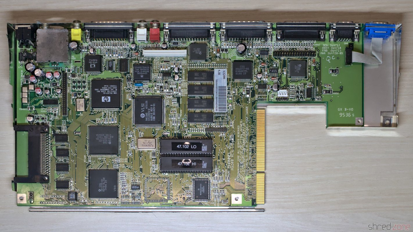
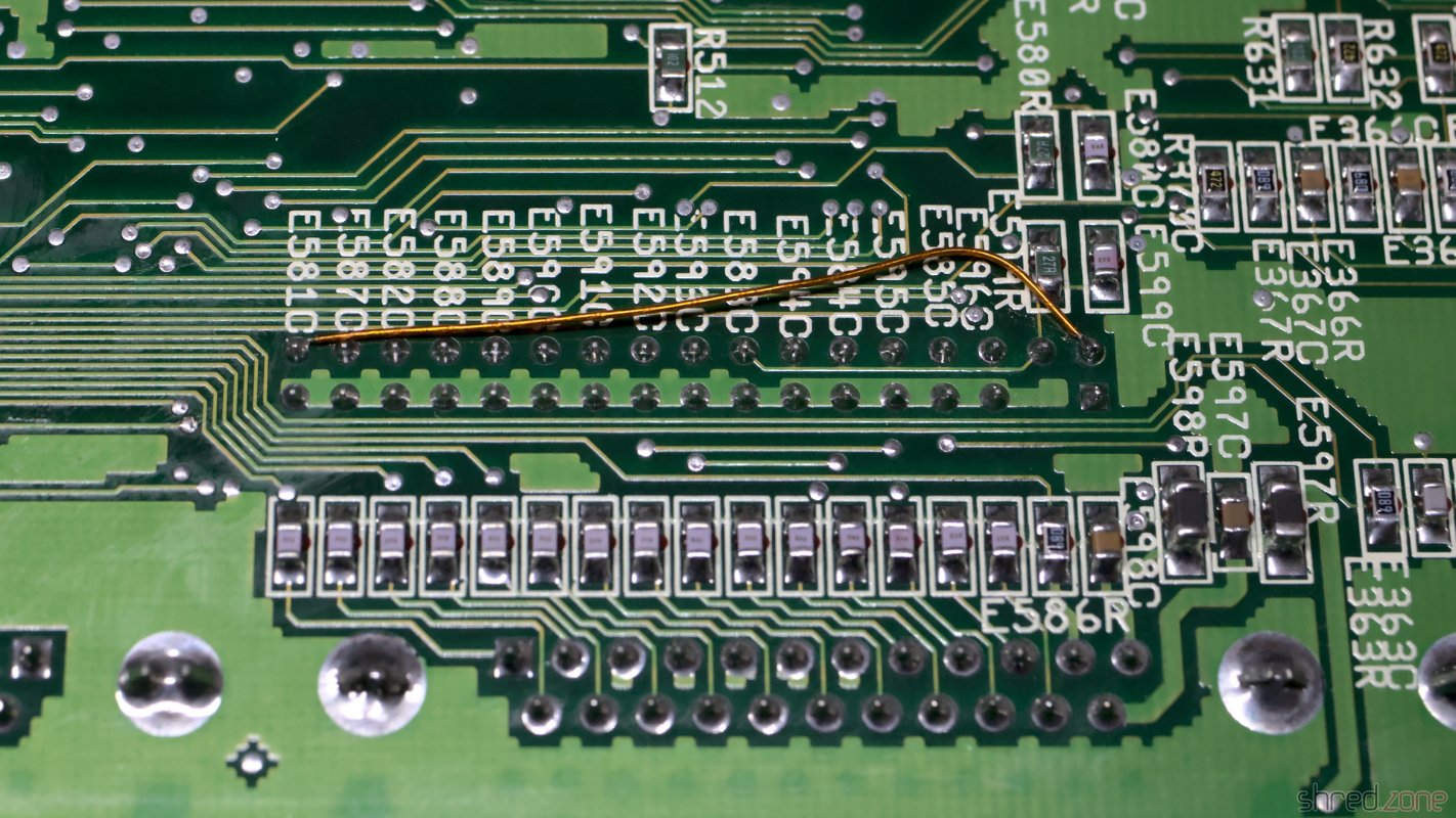
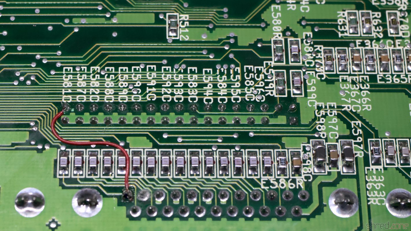
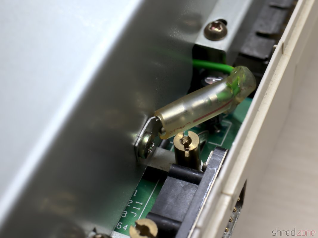
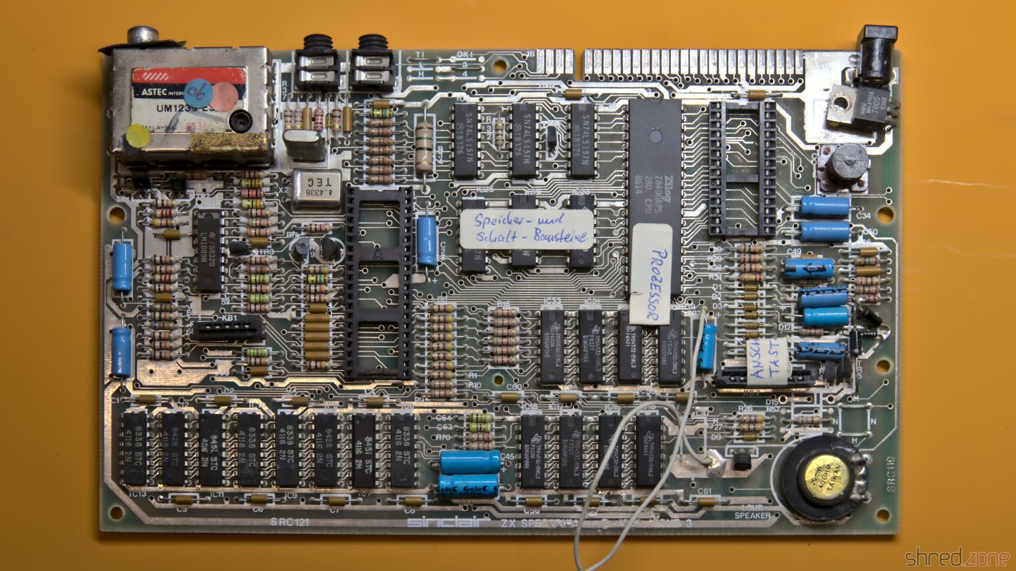
 I got this board of a Sinclair ZX Spectrum. It must have been a ZX Spectrum Plus model before, because there was this reset wire attached to it. There were also a few labels that were explaining the functionality of the components in German language, maybe for educational purposes.
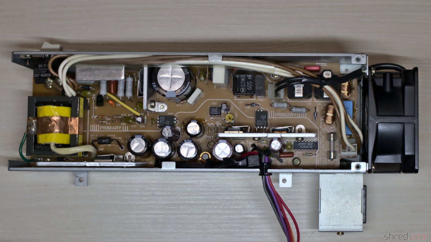
I tried to run the diagnostics, but the module didn't even start, and the D0 LED was permanently dark. There must have been a short circuit somewhere on the data bus. But instead of repairing it, my plan was to make a completely new ZX Spectrum from as many new components as possible, with reusing only the ULA, CPU, LM1889N, the coil, and the RAM chips.
So I first removed the valuable components. The stripped original board was a sad sight, but the prospect of making a new Speccy from it made it less painful.
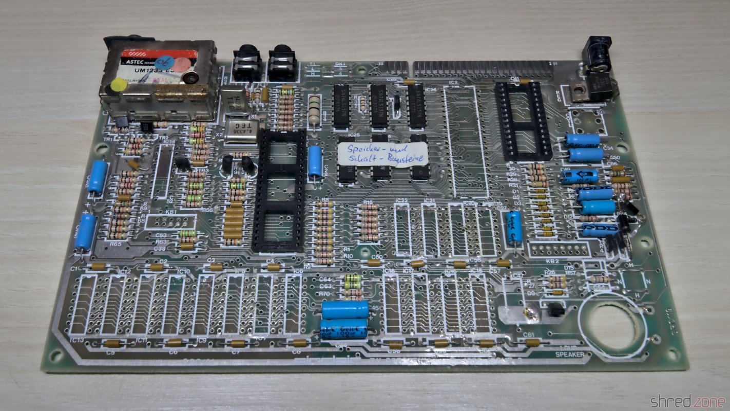
I checked the ULA in another Speccy, and it turned out to be fine. From the 16 RAM chips however, only 9 were still functional. This was much less than I expected. I'm having some of those old RAM chips in my stock, but they are precious and hard to find.
A New Board
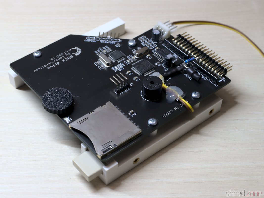
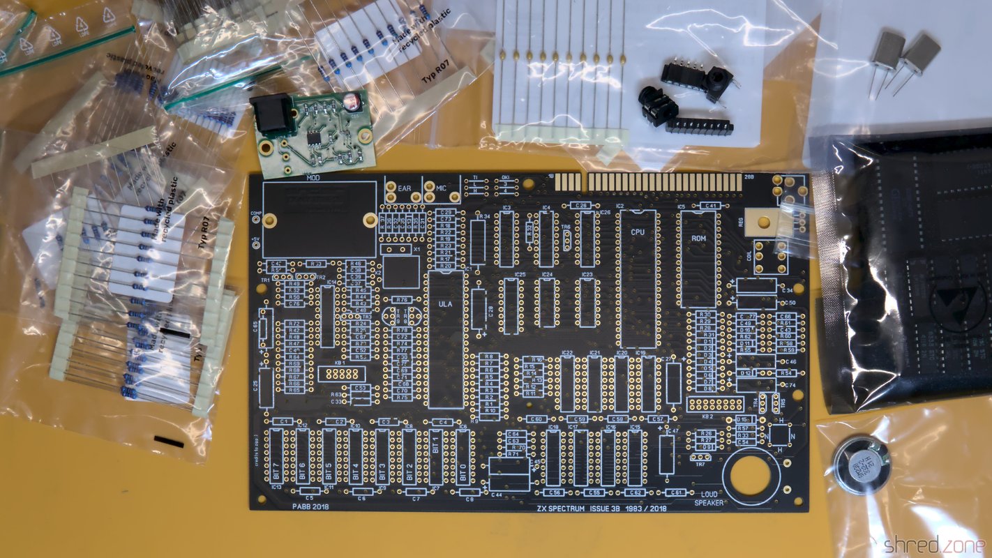 The new replica board is made by PABB and can be ordered from PCBWay.
For the required components, I assembled a bill of materials. It contains as many new components as I could find, but some rare parts are long out of production. They can still be found as NOS parts at online marketplaces, or they can be replaced with replacement types or replicas (like the Retroleum Nebula or vRetro vLA82).
There are four wire bridges that configure the type of the upper RAM chips, and the brand of the ROM chip manufacturer. The correct configuration can be found in my bill of materials as well.
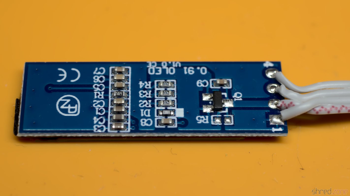
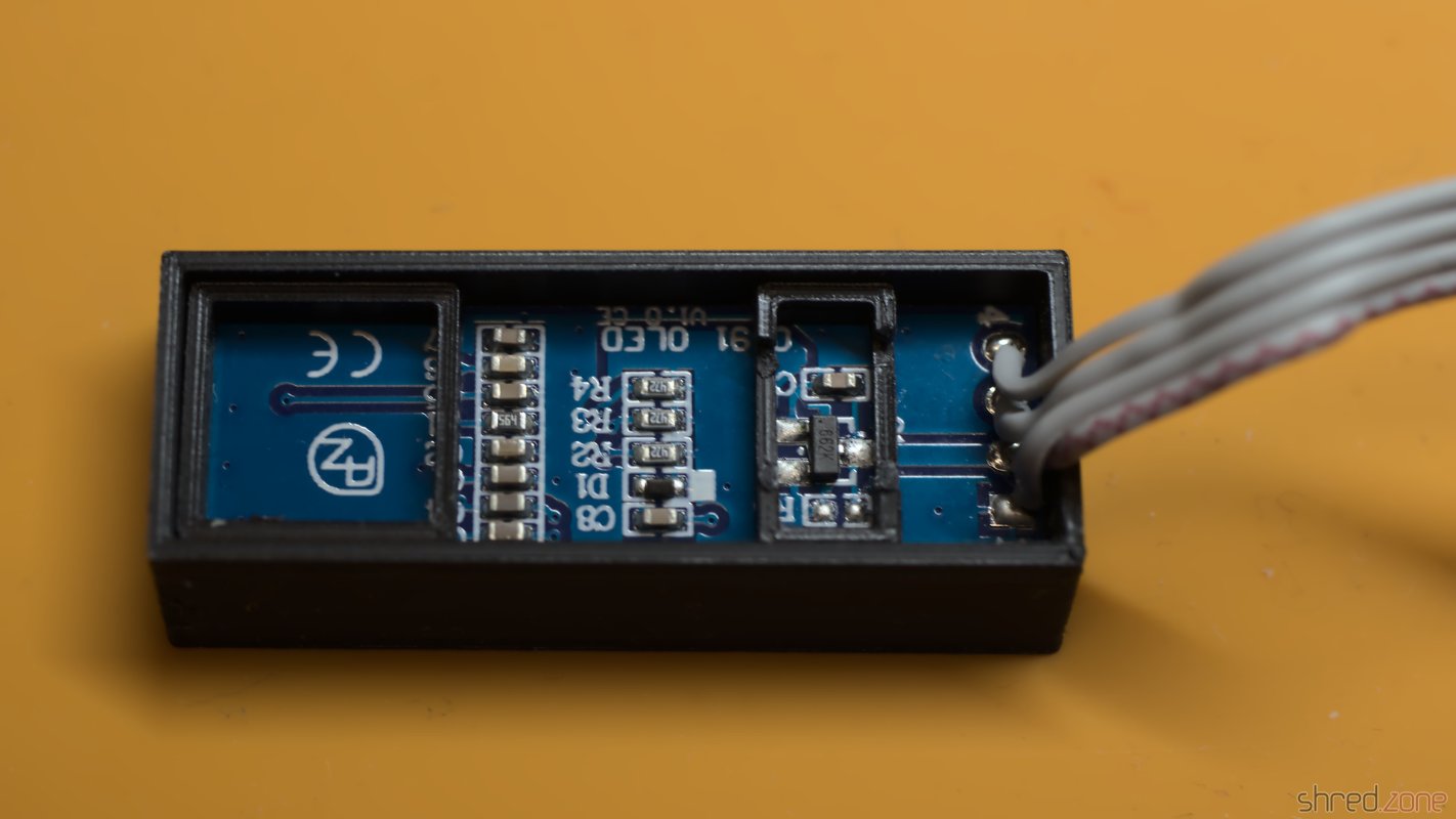
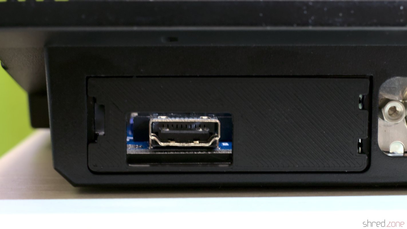
Instead of the modulator, I decided to use an S-Video mod and a 3D printed base plate. A simple alternative is to just solder an RCA connector to COMP and GND, and use it as a composite output.
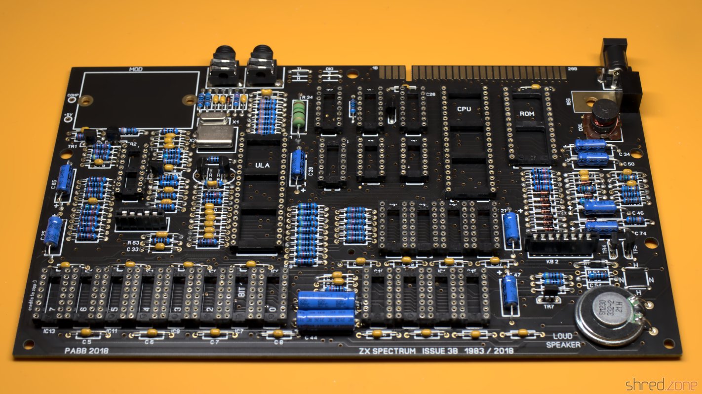
After a lot of soldering, the assembly was almost completed. But before seating the valuable chips, I first checked that all three voltages (+5V, +12V, -5V) were present and within their acceptable tolerance.
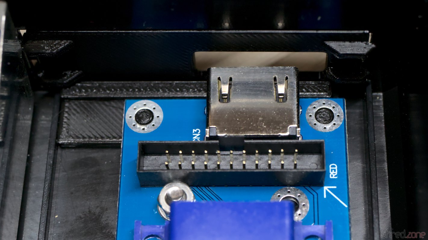
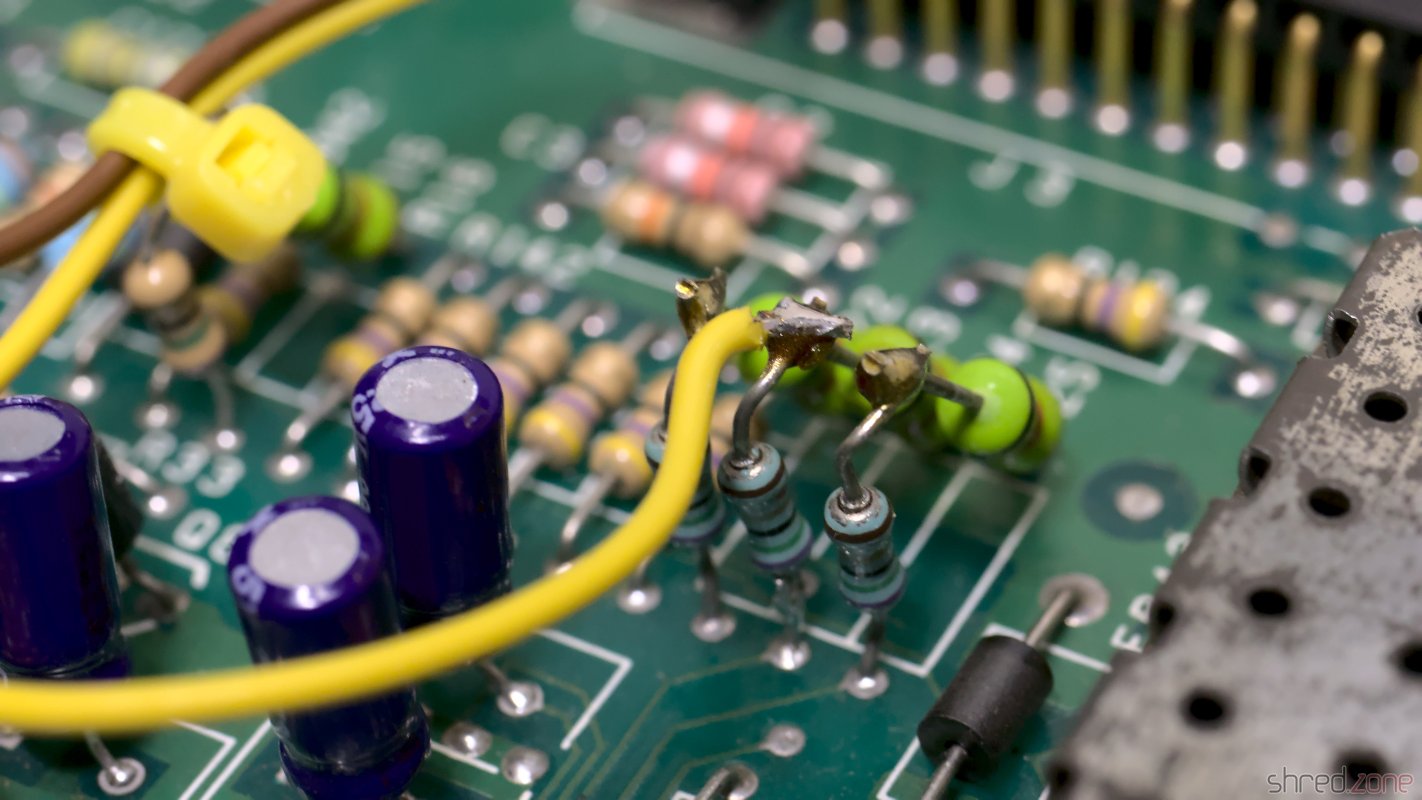
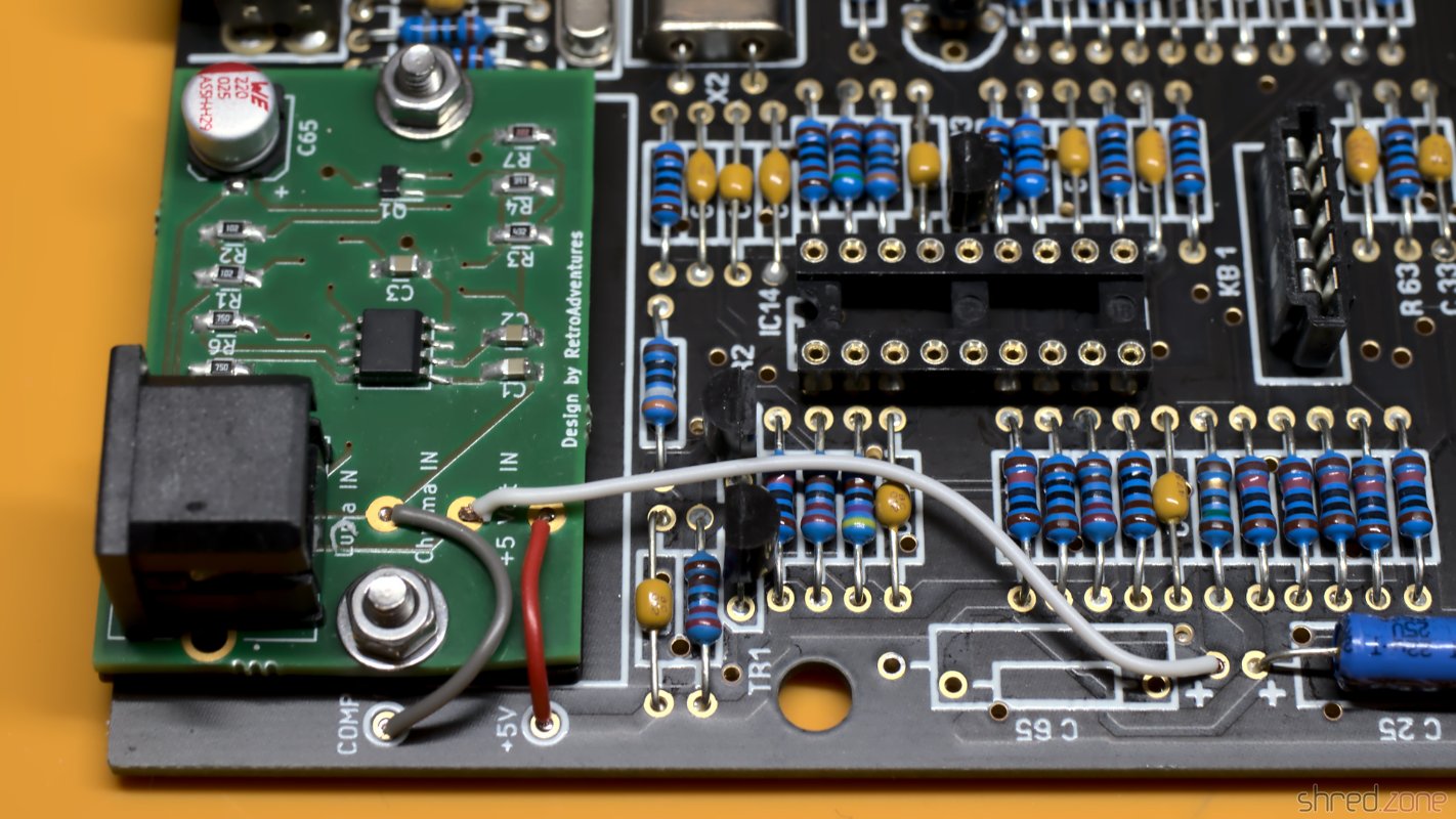
The S-Video mod takes the place of the original modulator, but is not soldered in, but held by two screws. The screws also provide ground, so they must not be isolating. Three wires then connect the board with +5V, and the composite signal as luma. The chroma signal is connected to the positive end of C65, which must be removed first so the luma and chroma signals won't mix.
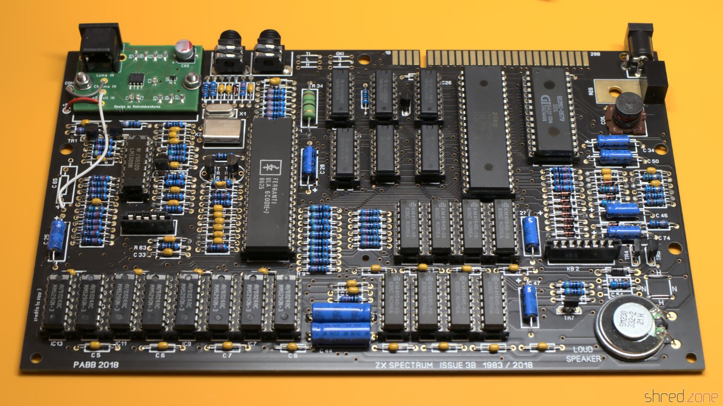
After that, the new board was finally completed and ready for a first test.
Bugfixing
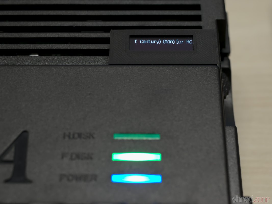
But alas, this is what I was seeing when I powered it up for the first time.
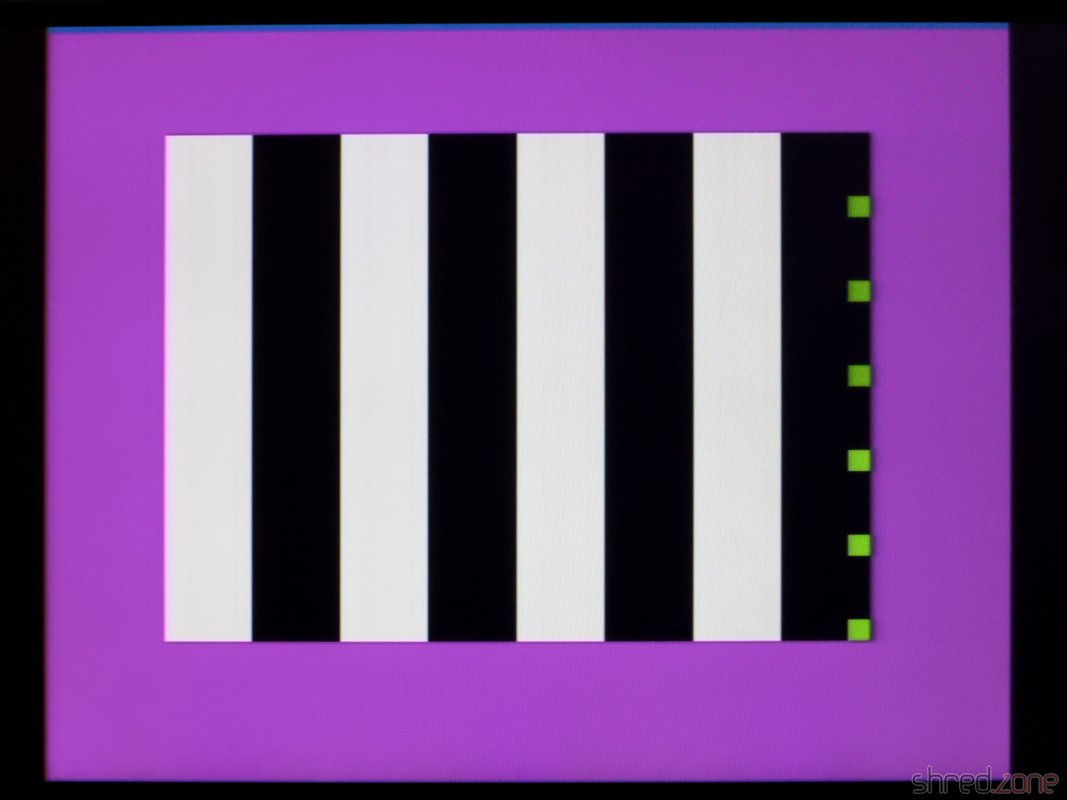
The diagnostics showed no action on the CPU bus controls. My suspicion was confirmed when I checked the clock input of the CPU with a scope. It was just a flat line:
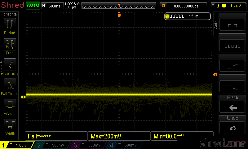
The CPU clock is generated by the ULA, but the clock signal was present there.
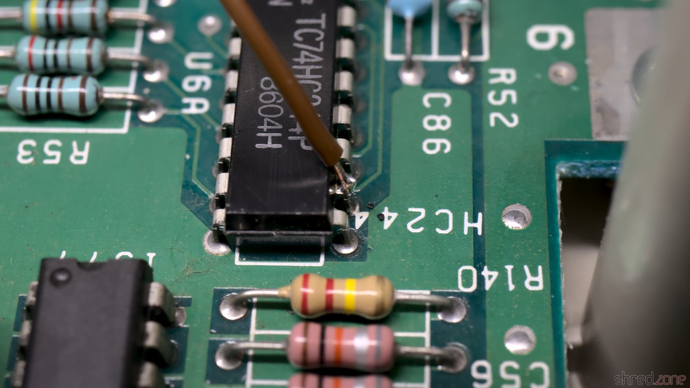
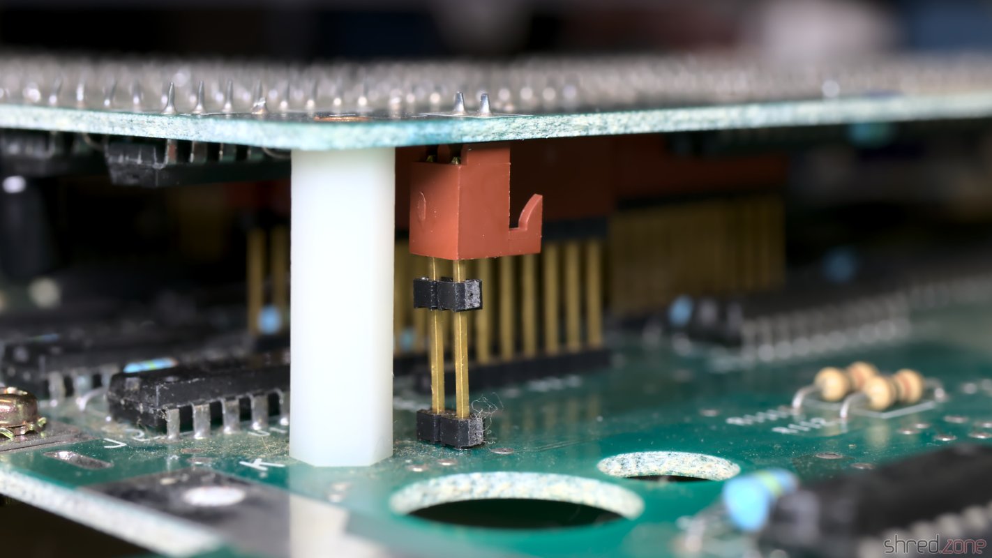
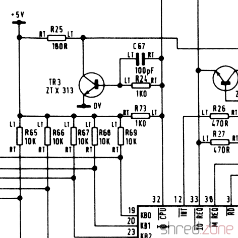
A look into the schematics shows that between the ULA clock output and the CPU clock input there is the transistor TR3, probably for amplifying the signal. Strange enough, the signal was still present at the right of R24, which is directly connected to the clock output, but at the left of R24 (which is connected to the base of the transistor) the signal was missing already. When I removed TR3, the clock signal appeared there too, so TR3 must have been the cause.
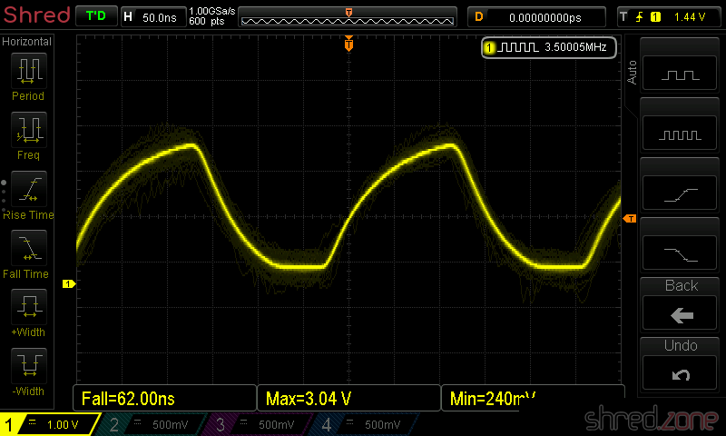
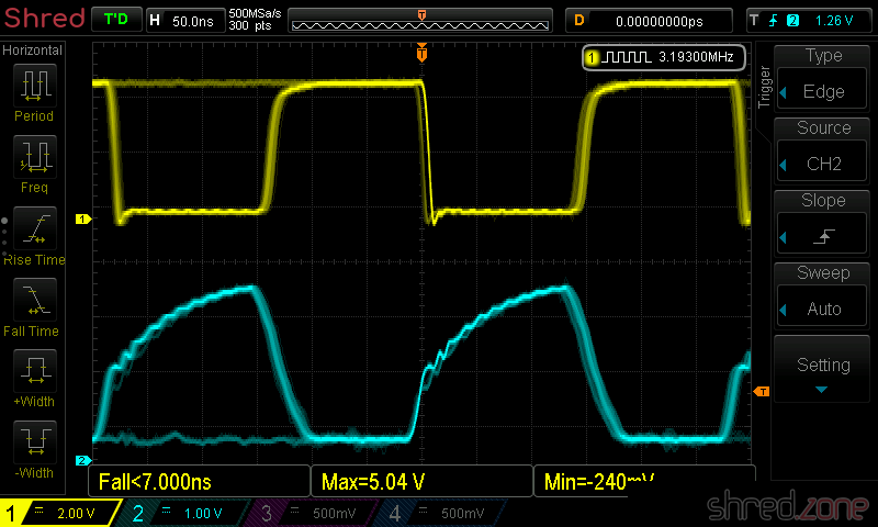
After a longer search, I found out that the Spectrum is very picky about the type used for TR3. The original ZTX313 is not in production anymore, so I used a BC548 first, which is said to be a replacement type, however not at this position. For TR3, the only recommended replacement type is the MPS2369, which is also a bit hard to find now. With that type, the clock signal was finally good (cyan: ULA clock output, yellow: CPU clock input).
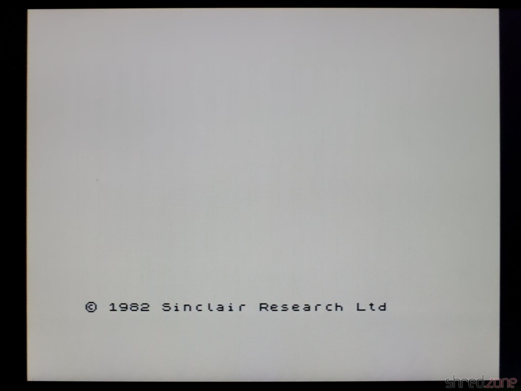
And to my joy, the new Spectrum finally started up and showed the famous start screen.
The next step was to run a full diagnostics check. Now I got an error that the M1 signal was missing.
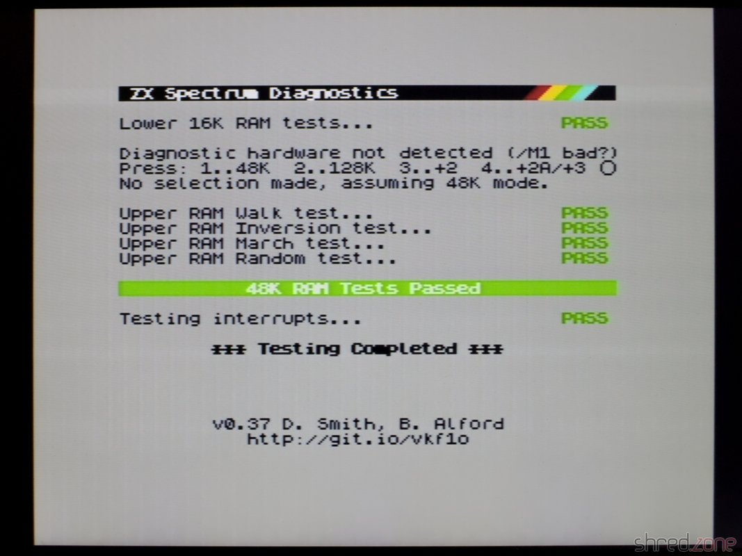
The M1 signal is generated by the CPU, and indicates the first of four machine cycles, which is the cycle where the next instruction is read from memory. The Spectrum itself does not use the M1 signal, but a few expansions like the ZX Interface 1 need it.
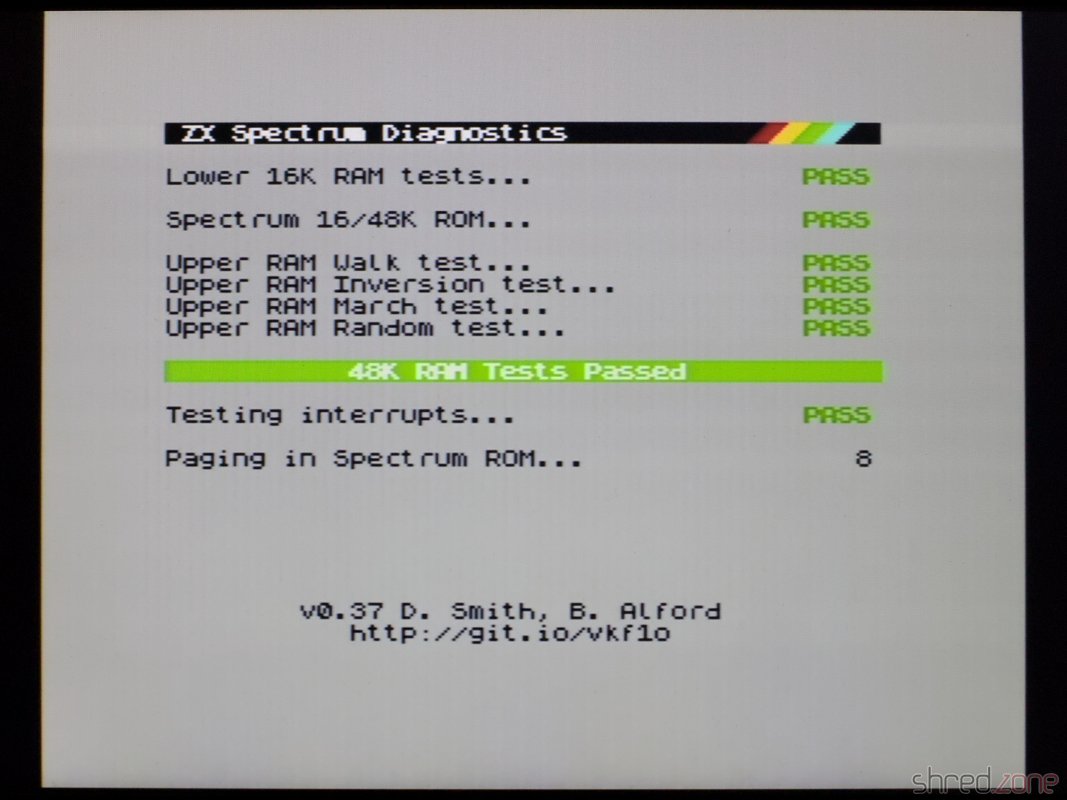
After replacing the CPU, all diagnostics checks finally passed.
So at the bottom line, all I could reuse from the old ZX Spectrum was the ULA, the ROM, the LM1888N and the coil. I was hoping for the RAM chips and the CPU, but I haven't been really lucky with them.
Test Run
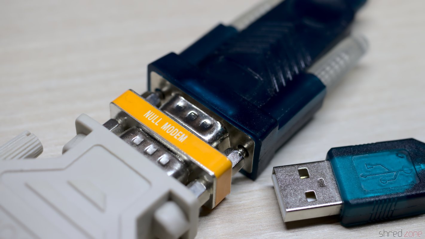
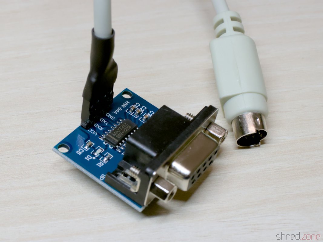
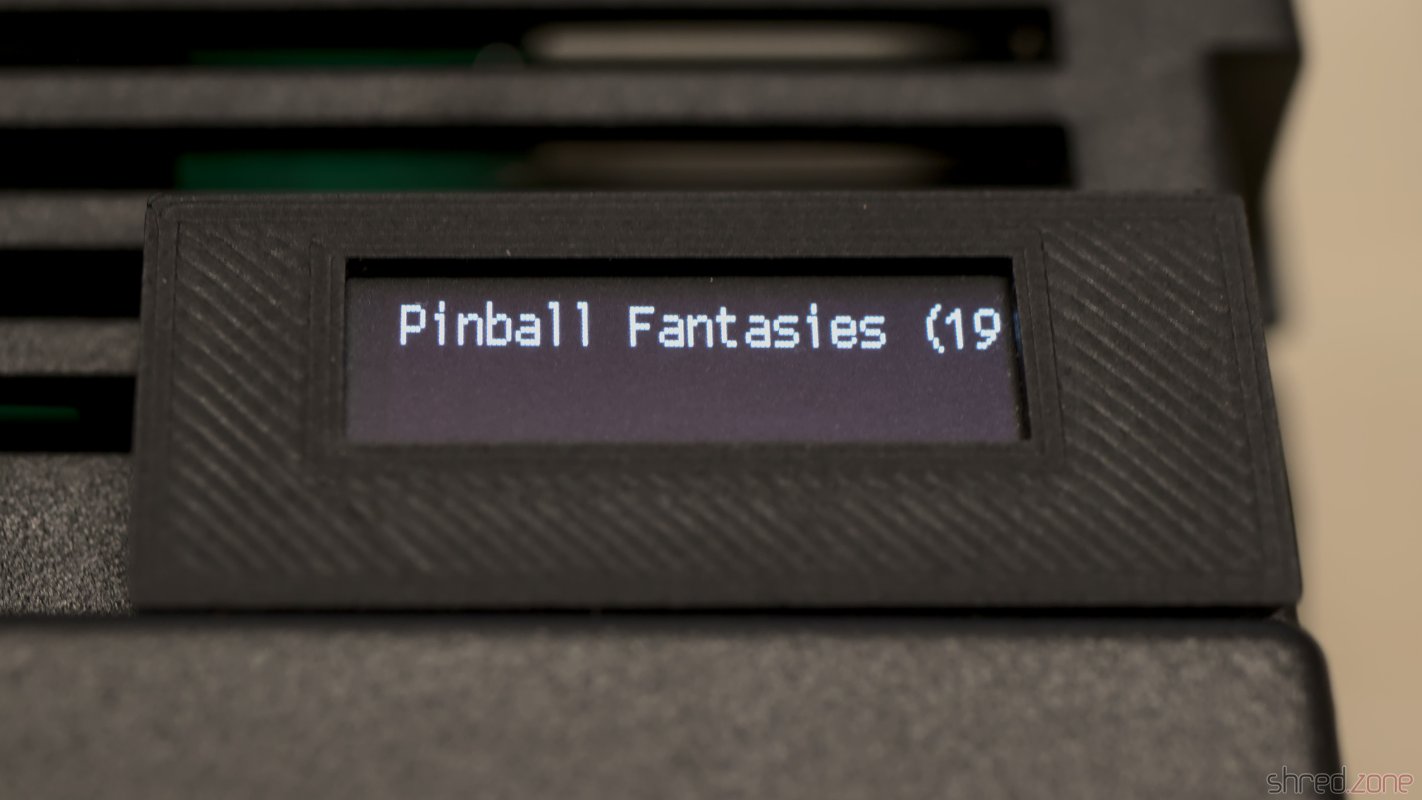
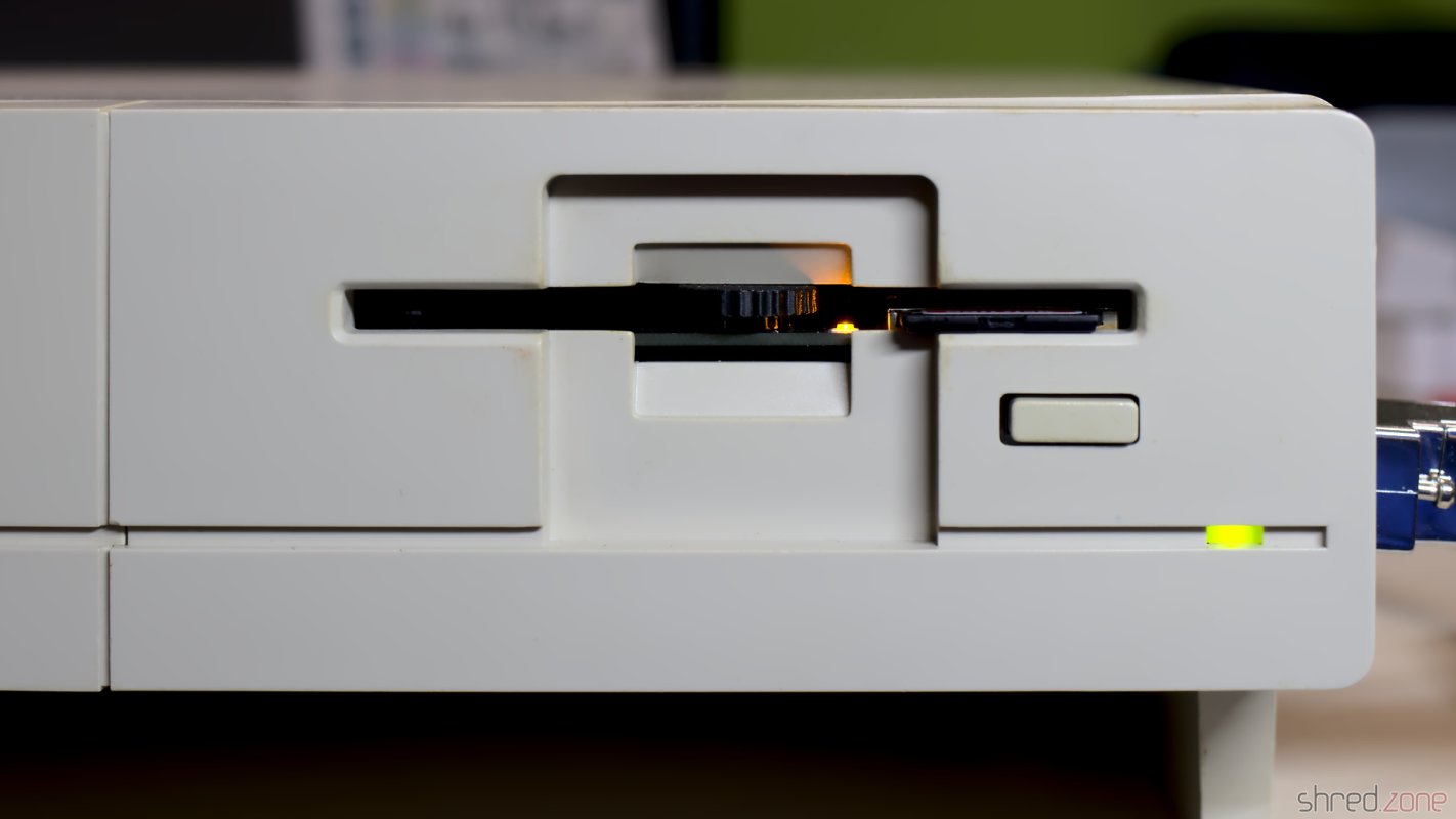
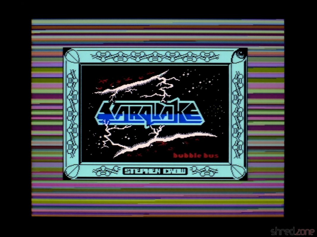
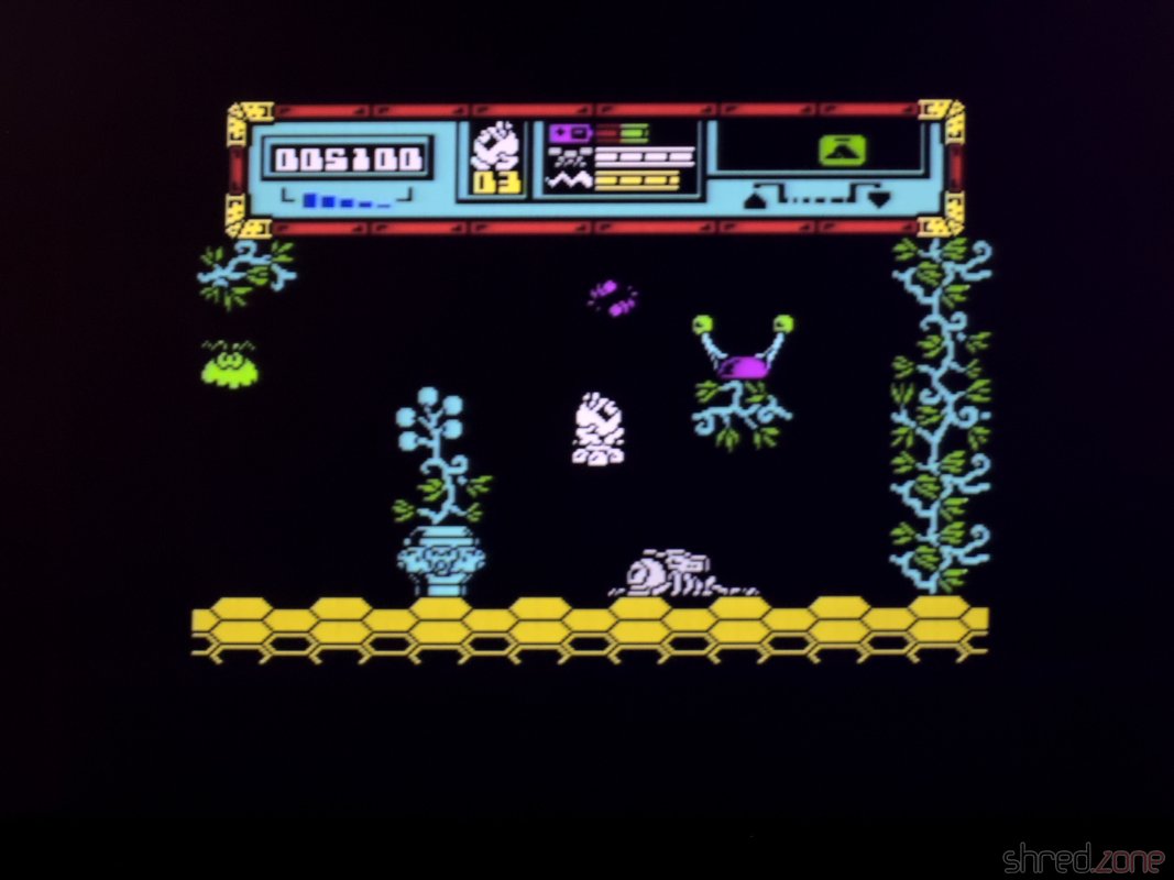
Anyway, it was finally time for a test run. I connected the new Speccy to my computer, and used tzxplay to play the tape file of my favorite game, Starquake. It was loading and running fine. Also, the image quality of the S-Video output is excellent, and probably the best one can get from this old design. Only the ZX Spectrum Next has a better quality with its native, pixel perfect HDMI output.
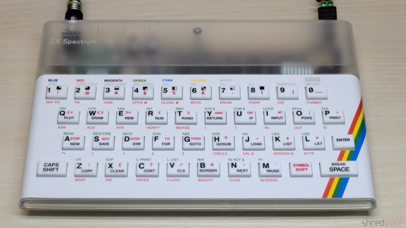
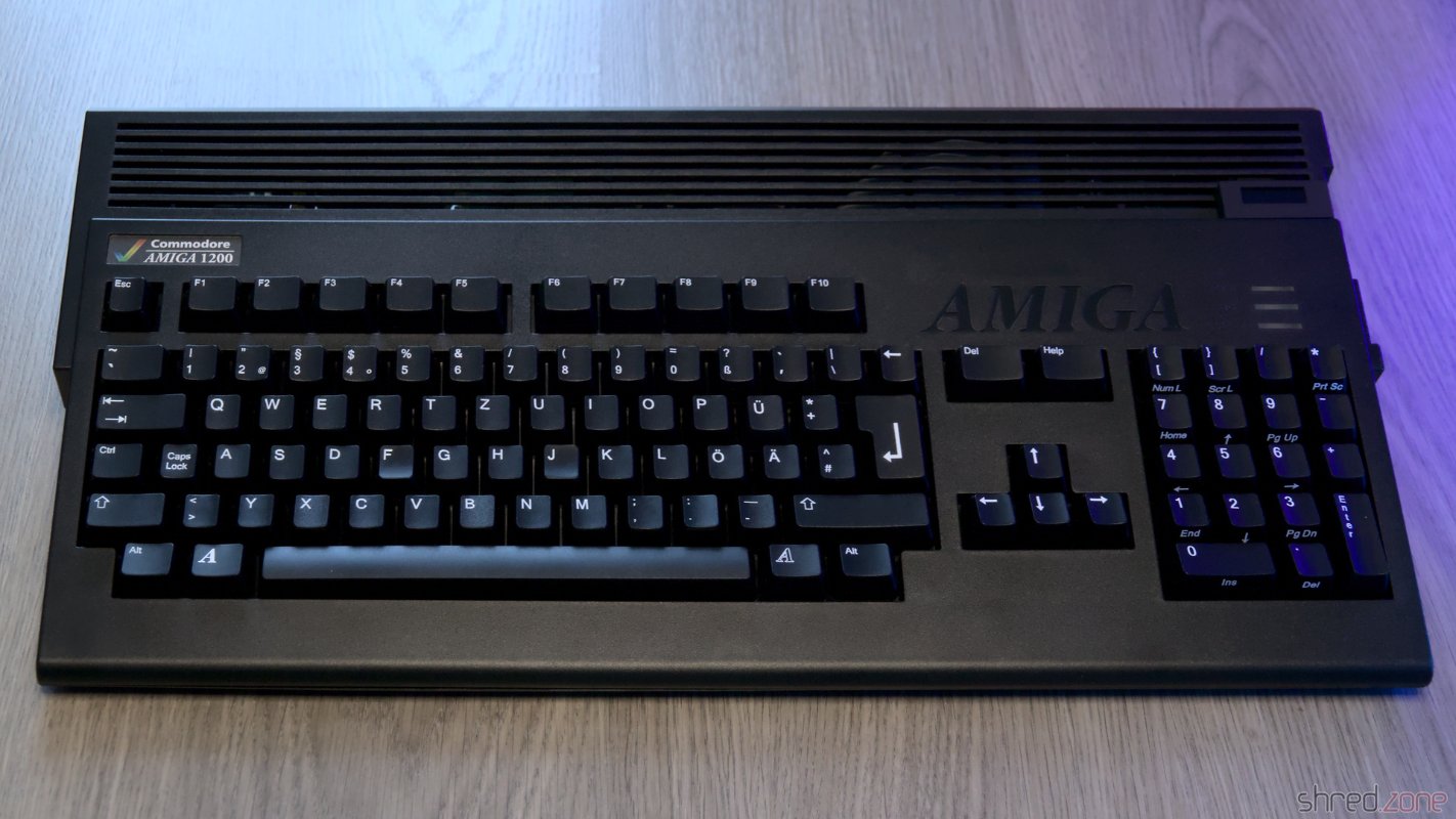
I bought the original board without any case. But luckily, there are replica cases, keymats, membranes, and faceplates on the market, so I could assemble a brand new outerior. Of course, I chose a transparent case, so the nice black mainboard could be seen from the outside. Well, at least a bit.
And there it is, an (almost) new ZX Spectrum in mint condition.