Retro.Know-How

RetroChipTester firmware update

The Retro Chip Tester (short: RCT) by Stephan Slabihoud is a chip tester that can test an incredible amount of RAMs, logic chips and other retro components. The good thing is that it is also affordable and fun to assemble.
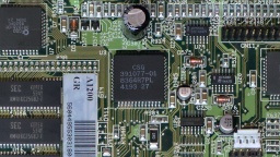
After I skipped three updates, I thought that a firmware upgrade to the current v0.26 was now overdue. This article is rather meant to be a guide for myself, but maybe you will find it useful as well. It is only about a firmware update though. For an initial setup, you will first have to set the fuses of the ATmega, which is not part of this article.

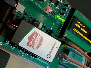
To perform this update, I used a Fedora Linux with avrdude installed, and a Microchip PICkit 4 (just because I have one at hand). Other programmers will do as well (see the RCT documentation), maybe it's even possible to use a Raspberry Pi for it.

First I connected the PICkit to the ISP connector of the RCT:

1MISOMOSIGNDSCKVcc/RESET23456

Signal PICkit RCT
(NC) ⯈ 1
VTG 2 2
GND 3 6
MISO 4 1
SCK 5 3
/RESET 6 5
MOSI 7 4
(NC) 8

Please check twice that everything is connected properly, otherwise you can damage your hardware. Also remove an SD-Card reader module (if present), as it will block the ISP port.

According to the documentation, the RCT must not be powered by an external power source and the programmer simultaneously. The VTG line does not provide power though, but is used as a target voltage input by the PICkit. It is still necessary to power the RCT externally (e.g. by USB or by a barrel plug).

I then downloaded the firmware and unpacked the zip file. Now all there was left to do is to change into the directory where the archive was unpacked, and run avrdude:

avrdude -Cavrdude.conf -v -patmega2560 -cpickit4_isp -Pusb -xmode=avr \
  -Uflash:w:Chip-TesterPro-FW-v0.26.hex:i

(Remember to amend the bottom line to match your firmware version.) If the following error should appear, just run the command again:

avrdude jtag3_open_common() error: PICkit 4 in PIC mode detected
        switching to AVR mode
        please run Avrdude again to continue the session

If the flashing process should fail, you can always fix the problem and do another flash attempt.

Amiga Debugging with Linux

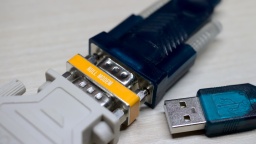
A "zero modem" adapter between the serial-to-USB and DB9-to-DB25 adapters The AmigaOS offers a debug console as a simple way for debugging. Log data can be written via the linkable Debug.lib, which is also used by all kind of tools like MuForce, Mungwall, or PatchWork. AmigaOS provides a simple internal debugger called ROMWack (which has been replaced by the even simpler SAD in later versions). But also DiagROM is writing diagnostics data via the serial port, which comes in handy when a RAM chip or something in the video area is broken.

The log output is sent to the serial port and can be read by a terminal connected to it. Back in the good old days, not so many hobbyists could afford an actual terminal or a second computer for that, so we used tools like Sushi or Sashimi to redirect the debug output into a Shell window, which worked fine unless the system has crashed too hard.

Today, I assume that almost all of the Amiga owners also have a second computer at home, and if it's just a second Amiga. 😉 This blog article is about how to connect your Amiga to your Linux PC, and get the debug output.

On the hardware side, you will need a construction with a DB25 female port on the one end, and an USB connector on the other end. I use one of those USB-to-Serial converters that can be found on hardware shops for little money. They are often equipped with a DB9 male connector, and are supposed to be connected to peripheral devices (like modems). To connect them to a computer, a so-called zero modem (or null modem) is required, which is just a small adapter that enables to connect two computers directly together by crossing the transmit and receive lines. Finally, we need a DB9-to-DB25 connector with the correct genders, to connect the other end of the zero modem to the Amiga.

This hardware stack is connected to the Amiga's serial port on the one end, and to a USB port of the PC on the other end. Remember to turn off the Amiga before connecting something to the serial port. Unlike USB, the ports of old computers are not designed for connecting or disconnecting devices while the system is powered. It could actually damage the system to do so!

On the software side, we don't need to install drivers on the Amiga. The debug or diagnostics output is just sent to the serial port. On Linux, we can use any terminal emulator. The most prominent is certainly minicom.

The default serial port settings are 9600-8N1 (9,600 bps, 8 bits per character, no parity, 1 stop bit). However, the debug output is just directly sent to the serial port. If you changed the serial parameters on Amiga side, and used the serial.device for something else, the debug output will use the current settings. Handshake must be turned off in any case, though.

Maybe the easiest way is to create a file called ~/.minirc.amiga with the following content (change the pu port value to your actual TTY USB device):

pu port             /dev/ttyUSB0
pu baudrate         9600
pu bits             8
pu parity           N
pu stopbits         1
pu rtscts           No
pu xonxoff          No

On many Linux distributions, the user also needs to be added to the dialout group in order to access a serial device:

sudo usermod -aG dialout $(whoami)

After that, just start minicom with the amiga profile:

minicom amiga

Now you should see all the debug output generated by AmigaOS on your minicom screen. For interactive debuggers like ROMWack, you can also type commands into the console.

To leave minicom, press CTRL-A and then Q. 😉

Amiga CD32

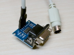
A TTL-to-DB9 converter board and a PS/2 cable connected to it Unlike other Amiga models, the CD32 has no dedicated RS-232 port. Instead of that, it provides a simple serial interface at the Aux port that is connected to Paula's UART pins internally.

To build an adapter, you need a PS/2 cable (e.g. from an extension cord or an old PS/2 input device) and a MAX3232 based TTL-to-DB9 level converter. These converters can be found at online marketplaces for a few Euro.

Cut one end of the cable and connect the wires to the converter like that:

  • Pin 2: TXD
  • Pin 3 (and the shield): GND
  • Pin 4: VCC
  • Pin 6: RXD

Leave the remaining two wires unconnected, and check for correct polarity before connecting the wires to the converter!

The CD32 does not provide any control and handshake signals, but fortunately they are not needed for debugging and diagnostics purposes.

Amiga 1200 Mouse Button Fix

While I was restauring an Amiga 1200, I noticed that on that machine, the right and middle mouse buttons did not react on both ports. Checking it further, it turned out that it was working with an original Amiga mouse, but failed with my YAMI mouse interface. The mouse interface could not be the cause though, as it is actually working reliably for decades on all kind of Amigas, including an Amiga 1200.

The problem is already known to the community, and also seems to affect other mouse interfaces. The mitigation options I could find so far were:

  • Just use the original Amiga mouse. 😉
  • Modify the mouse interface. There is a "fixed" version available for some of them.
  • Use a "FixRMB" tool. This tool needs to be started first though, so it won't work for reaching the boot menu or in games. It also requires a mouse interface with internal pull-up resistors. (YAMI does not have those, for example.)
  • Some said they were lucky with replacing the Paula chip, but it requires experience in soldering.

None of these options is really appealing to me. I want this Amiga to work like all the others. So I tried to figure out what is the actual problem here, and how to fix it properly.

The middle and right mouse buttons are connected to the POT pins of Paula. These inputs are actually made for analog joysticks, and provide a very simple ADC. The analog joystick charges a capacitor, while a counter inside Paula is taking the time. As soon as the voltage of the capacitor reaches a certain level, the timer is stopped. The position of the joystick can be evaluated by the time it needed to charge the capacitor.

But there is also a digital mode, which is used for mouse buttons. If enabled, a resistor inside Paula pulls up the POT line. If the mouse button is pressed, the mouse switch pulls the line to LOW, which can then be read from the Paula registers.

When an original mouse was connected, the POT line was pulled to 0.9V while the button was depressed. However, when the mouse interface was connected, the line was only pulled to 1.1V. It seems like a tiny difference, but for this Paula chip, it already makes the difference between "button pressed" and "button released".

The affected Paula with "4193" date code. Only a certain batch of Paula chips seems to be affected. This is the reason why this problem does not occur on all Amiga 1200, but presumably only on some 1D.4 boards. This is also the reason why replacing the Paula chip is fixing that issue. On my board, a "CSG 8364R7PL" with date code 4193 is used. I also heard of one more case with a Paula chip of the same production week.

Next question: Why only Amiga 1200 models seem to be affected by this issue, although it is likely that the affected Paula batch was also used in Amiga 4000 production? When comparing the schematics of both machines, there is a notable difference. This is a simplified extract of the joystick or mouse port:

SVG Picture created as paula-pot.svg date 2022/10/10 11:01:53Picture generated by Eeschema-SVG112233445566778899POTYPOTYPOTXPOTXSVG Picture created as paula-pot.svg date 2022/10/10 11:01:53

The difference is in the parts marked with a red circle. They are used as EMI filter. For the Amiga 4000, Commodore has used ferrites there. It is basically just a wire inside a ferrite bead, giving a resistance of 0Ω at low frequencies. In the Amiga 1200 (and Amiga 600) though, Commodore used standard 68Ω resistors, presumably to cut costs.

Together with the pull-up resistor inside Paula, this resistor works as a voltage divider. The switch inside a classic Amiga mouse pulls this divider to ground, giving 0.9V at the POT input, just enough to get detected as LOW.

SVG Picture created as paula-pot.svg date 2022/10/10 19:43:20Picture generated by Eeschema-SVGMouse Button68ΩPOTPaula Pullup0.9V5V0V68ΩMouse ButtonPOTPaula PullupSVG Picture created as paula-pot.svg date 2022/10/10 19:43:20

The mouse interface does not have a real switch though, but a logical output. For example, the PIC16F84 that is used in the YAMI interface provides a LOW voltage of 0.6V. Now the voltage divider gives 1.1V at the POT input, which is interpreted as HIGH by Paula.

SVG Picture created as paula-pot.svg date 2022/10/10 19:43:20Picture generated by Eeschema-SVGMouse InterfacePaula PullupPOT68Ω5V0.6V1.1VPaula PullupPOT68ΩMouse InterfaceSVG Picture created as paula-pot.svg date 2022/10/10 19:43:20

I could not find out if the pull-up resistor inside Paula has a lower resistance in that batch, or if there is a different threshold for detecting LOW levels. Both would be possible.

To fix the problem on my Amiga 1200, I replaced the 68Ω resistors E353R, E354R, E363R, and E364R with the SMD 1206 ferrites that are used in the Amiga 4000. They are a bit bigger than the 0804 resistors, but can still be soldered straight to the pads.

The position of the replacement ferrites at the bottom side of an Amiga 1200 board.

This is just a minor change to the hardware that could be done even by soldering novices (at least rather than unsoldering a PLCC chip). After that change, the mouse interface was working too.

Make sure to replace the resistors with ferrites, not the capacitors next to them!

PS: If you found this article because your Amiga is also having the problem, please send me the date code of your Paula chip. Maybe we can find a pattern of "bad" date codes. Thank you!

PPS: Commodore did the same trick on Amiga 600 machines, so if you have trouble with the right mousebutton on your A600, it's worth a try to replace E353R, E354R, E363R, and E364R.

MaestroPro Internal

MacroSystem Maestro Professional In the mid 1990s, MacroSystem Germany released the Maestro Professional sound card for the Amiga. It was a special sound card because it was fully digital, having only optical and coaxial digital connectors. It was suited for lossless recording from CD and DAT, as well as generating lossless audio output for DAT recordings. With tools like Samplitude, the Amiga became a studio quality digital audio workstation. There was also a tool for doing backups on DAT. At that time, these tapes were the cheapest way to backup entire harddisks (a 90 minutes DAT tape could backup almost 1 GB of data, which was a lot in the 1990s).

Unfortunately MacroSystem had never released a driver for the sound card, so it could only be used by a few (and mostly commerical) tools. I pestered their developers at every Amiga fair I could attend, but to no avail. Then, at the end of 1994, I decided to find the datasheets of the Yamaha chips, reverse engineer the board design, and write a driver myself. It took some time of trial and error, but eventually I was successful. In the coming years, my driver, the maestix.library (source code), became the inofficial standard driver. OctaMed Professional is maybe the most prominent software using it. Some professional music artists used Amiga and OctaMED for their production, so maybe my driver was even used for recording the masters of some famous CDs? 😁

Digital Audio in a Nutshell

The MaestroPro is able to receive and transmit digital audio data, either in the S/P-DIF or AES-EBU standard. The former one is still widely used in home equipment today, while the latter one was rather common in studio equipment. Today's standards permit different encodings and high sampling rates, but the MaestroPro could only read 2-channel 16-bit raw audio with sampling rates of either 48kHz (DAT), 44.1kHz (CD), or 32kHz (DAB).

Besides the raw audio data, the standard also transports Channel Status Bits (CSB) and User Data Bits (UDB). The CSB contain information like the used sampling rate and the copy prohibition state. The UDB are not standardized, and usually transport proprietary data between studio equipment.

Inside the Maestro

The board's design is straightforward. It mainly contains a transmitter, a receiver, and FIFO memory for transporting the samples between the board and AmigaOS.

Receiver
YM3623B DIR
Receiver...
Transmitter
YM3437C DIT2
Transmitter...
Serial to Parallel
Serial to Parallel
Parallel to Serial
Parallel to Serial
R-FIFO 1Kx16
R-FIFO 1Kx16
T-FIFO 1Kx16
T-FIFO 1Kx16
DATA BUS
DATA BUS
Board
Controller
Board...
UDB Shift Register
UDB Shift Register
Sampling Clock
Sampling Clock
48kHz
48kHz
Optical
Optical
Coax
Coax
Optical Out
Optical Out
Input Signal
Input Signal
FIFO
FIFO
Bypass
Bypass
In
In
Source
Source
UDB Data
UDB Data
Text is not SVG - cannot display

The optical and coaxial inputs go to a Yamaha YM3623B Digital Audio Interface Receiver (DIR). This chip decodes the audio data stream, extracts the CSB and UDB, and generates a raw bit stream of the audio samples. Shift registers convert it to a 16 bit parallel stream, which is stored in a 1K x 16 bit receiver FIFO. As soon as the FIFO is half filled, an interrupt is raised, and the Amiga driver reads the received data from the FIFO. This happens up to 190 times per second.

The most important CSB are readable via a status register of the board controller. The UDB are copied to a separate 8 bit shift register, which could be polled by the driver. However, UDB are usually 32 bit wide, so reading them was never really used in practice (at least not to my knowledge). The Maestix driver only provided a very rudimentary API for the UDB.

On the transmitter side, the 16 bit samples are pushed to a transmitter FIFO, and then converted to a serial bit stream by shift registers. A Yamaha YM3437C Digital Audio Interface Transmitter (DIT2) converts it to a digital audio stream and sends it via an optical output. The Maestro Pro does not have a coaxial output, presumably because there was not enough space on the board for a fourth connector.

The DIT2 is unable to generate the sampling rate clock by itself. It needs an external clock source instead. On the Maestro Pro, this clock is generated by the DIR. It is either derived from the bit stream of the selected input, or generated by an internal fixed 48kHz clock source. For this reason, the Maestro Pro needs to rely on external signal sources for 32kHz and 44.1kHz output sampling rates.

The transmitter can choose from two data sources. One source is the transmitter FIFO. The other source is the bit stream from the DIR, bypassing the FIFOs. This enables the board to modify the UDB and CSB of the incoming signal directly, without involving the CPU. But since the transmitter and reciver paths are fully separate, the MaestroPro is even capable of providing full-duplex audio streaming. The maestix.library takes advantage of that with the "realtime FX" feature, where the signal is read from the receiver FIFO, modified by the CPU, and then immediately sent back to the transmitter FIFO.

The entire board is controlled by three GALs and a small handful of 74LS logic chips. They take care of the Zorro bus protocol, provide mode and state registers, and orchestrate the transmitter and receiver paths.

Broken MaestroPro

All of the components of a MaestroPro can still be found on the market, although both Yamaha chips are not produced any more and can only be found on some Chinese online markets as NOS parts. But basically, it is still possible to repair a broken MaestroPro.

The major weakness are the three custom programmed GALs. The GAL manufacturer states a memory retention time of about 20 years. It sounds like pretty much, but remember that these boards are almost 30 years old now. We already exceeded that life span by 50%!

When I reactivated my Amiga in 2021, my MaestroPro was working fine for a couple of minutes, but then it started to lose synchronization with the audio source. The only way to fix that problem was to turn off the Amiga and let it cool down for several minutes. A deeper diagnostics showed that the card seemed to detach itself from the Zorro bus. It seemed that one of the GAL chips had thermal problems, or was maybe starting to "forget" its programming. Fortunately I was able to recover the programming scheme. I replaced the original GALs with brand new Atmel ATF16V8C-7PU ones, and to my relief, my MaestroPro is now working stable again.

The fusemaps are copyrighted by MacroSystem, so I am not permitted to share them to the public. However, if you happen to have a broken Maestro Pro, please get in contact with me. Maybe I can help you to repair it.

The Maestro (without Pro)

There was a predecessor of this board. It was just called "Maestro", and had some major drawbacks. First of all, it had no transmitter and could only receive audio data. Secondly, it did not have a FIFO, so the sample words had to be read by the CPU as soon as they became available, which is up to 96,000 times per second. This was only possible by turning off multitasking and interrupts during recording, which also meant that recordings could not be written to harddisk, but had to be stored in RAM first.

Compared to its successor, the Maestro hasn't been a great success. I haven't seen one since the end of the 1990s, and I also don't know a single software that is actually using it. Due to the technical limitations, the Maestix driver won't support it.

Open-Sourcing old Amiga software

The Yamaha YM3623B Digital Audio Interface Receiver on a MaestroPro sound board After 22 years, I released an update of a software I wrote in the end 1990's for the Amiga platform. It is a driver for the MacroSystem MaestroPro, a fully digital sound board. Along with the update, I have opened the source code of that library.

The sound driver itself is not that interesting, actually. I don't think there are many people on this world still using the sound board. What's more interesting is how I changed the project, to make it open-source and compilable under Linux and other modern platforms. That's what this article is about.

Versioning (or the lack of)

The first problem I faced was rather unexpected. Back in the good old Amiga days, I hadn't used revision control systems like CVS. Being just a hobby developer, I didn't knew about their existence nor their purpose. Instead, I frequently made backups of my source codes, so I wouldn't lose them in case of a harddisk failure, or after a botched code redesign. But besides that, programming was a surgery on the open heart of the source code, with no way to revert to a previous state that was known to be working.

As result, I found multiple different versions of the project on my Amiga harddisk, and I had to figure out what the latest one was. In this project I was lucky, because I had added a changelog to the main file of the source. I just had to find the copy with the most recent changelog.

Without a revision control system, the source of all older releases are lost, so I didn't even try to recreate a history from the backups. The last version on the Aminet was V41.40, but I couldn't find the source of that release any more. What I found instead was a V41.50 that was never released. I cannot remember why I decided not to release that version. Maybe the changes turned out to be a regression? Maybe I just lost interest in the Amiga, and didn't bother to release it any more?

Anyway, I could at least find the latest version of the source code. What to do with it? As I became a professional software developer since then, it was clear to me that I would not go on with just keeping the latest source code version (and some random backups), but I wanted to use a revision control system now.

I prefer to use git today. It would fit nicely into my development environment, and would permit to publish my source codes in my GitHub repository. But git was never ported to the classic Amiga, and probably never will due to its complexity.

Olaf Barthel did a port of subversion though. The last release was in 2009, and bases on a very old Subversion version 1.1.4. It wouldn't be much fun to use it, but it would be feasible.

There is also a CVS port made by Frank Wille, but I never really liked CVS, so this was no option for me.

So svn and git were the only candidates, with a strong preference to use git, but svn as the only option that would work on AmigaOS. The decision was connected to the next question.

Compilation

On what platform do I want to continue developing?

I could go on and develop the project on the Amiga, like I did in the 1990s. I had everything I needed there. I used GoldEd as editor, with customized macros for compiling my projects. I used PhxAss as assembler, and SAS/C as C compiler. None of this software is still maintained, and SAS/C was a commercial product that is not available any more. With these strict requirements, just a few people would be technically able to participate in the project.

Today, Amiga enthusiasts use the vbcc toolchain for development. It is still actively maintained. And it runs on AmigaOS, but also on all major operating systems. As editor, Visual Studio Code is a preferred choice because there is an Amiga Assembly Add-on available. It supports syntax highlighting, inline documentation, debugging, and much more.

These are the missing pieces of the puzzle. With vbcc, it is possible to build the project on Linux and other platforms, so almost every Amiga developer is able to participate. Developing on Linux also enables me to use git and all the other tools I got used to. But with just a few modifications to the makefile, the project could still be built on AmigaOS.

I decided to go the Linux way, but it's a decision that every retro developer has to do for themself. Cross-building an Amiga project on Linux would be comfortable (and fast), but is not really "retro". Building on AmigaOS would be the true retro spirit, but would leave me with an outdated and partially unmaintained toolset.

Porting

It was easy to copy the source files to my Linux file system, and initialize a git project there. The next problem I faced was that I had to port the makefile. It was tailor-made to my AmigaOS environment, with special assigns for include files and binaries.

I created a new makefile that was using env variables instead. AMIGA_NDK now points to the unpacked AmigaOS 3.2 NDK, while AMIGA_INCLUDES points to the include files of external dependencies (like MUI). I installed vbcc so all the commands were in the $PATH.

After that, I restructured and rearranged all the source code files. The project now only contains my own files that are absolutely necessary for building the project. An invocation of make then builds the project on my Linux machine.

I18n

There was an unexpected problem with the charset. While all modern operating systems use UTF-8, AmigaOS does not support it, but uses ISO-8859-1 instead. The result is that the repository contained an awful mix of both charsets. All files that are intended to be used by the git environment (like the README.md file) are stored in UTF-8. Other files that are AmigaOS related (like AmigaGuide files) must be stored in ISO-8859-1 instead.

I was hoping that I could define the correct encoding for each file type in an .editorconfig file. But sadly, Visual Studio Code ignores the charset settings and instead uses UTF-8 by default. It was too easy to accidentally destroy all special characters (like the German Umlaut in my family name) that way.

The only solution I found was to use UTF-8 or ISO-8859-1 only where absolutely necessary, but for most files I used ASCII as the lowest common denominator. An own make target make check checks all files for illegal characters, enforcing the proper usage of the encodings.

Testing

Of course I want to test (and run) the result on AmigaOS, either in UAE, or on a real Amiga.

On UAE, the created files can just be copied straight to the Amiga harddisk directory, and then immediately used in the emulated Amiga.

For the real Amiga, it's a bit more difficult though. One way is to create an ADF disk file using xdftool, and copy the files to it. That ADF file can then be copied to an USB stick, and read in the Amiga using a Gotek floppy drive emulator.

A better way is to use a simple NFS server that is mounted on both the Linux and Amiga machines. Files can be easily exchanged that way. Of couse it requires that the Amiga has a network connection.

Release

Back in the Amiga days, making a release was a fully manual process. For this purpose, I had a separate directory with a release template. I manually copied all compiled files to the proper places of that template, then packed it, and uploaded it to the Aminet.

Now I want the git project to be self-contained, so all the files of the release template are in the distribution directory. The make release target builds the entire project, then creates a fresh release directory, copies all the files to the correct places, and creates an lha package.

On a modern Linux machine, the entire process (from a clean checkout to the distribution package) takes less than a second. 🤩

And that's it. The source of the maestix.library is now open and available at GitHub. The first release that was built on the new environment, can be downloaded from the AmiNet.

CI/CD

You may have laughed now, but it's true: It is possible to do CI/CD with Amiga projects!

vamos is a virtual Amiga runtime environment that permits to run simple Amiga commands on Linux. It's just a CPU and API emulation, not a full-blown emulator like UAE, but it is sufficient to run unit test suites.

There are Docker images like docker4amigavbcc that, for example, permit to automatically build commits using GitLab CI.

And since it's easy to upload new packages to the AmiNet, even Continuous Deployment would be possible. Just create a version tag, and let your CI/CD chain do the rest. 🙂

Altogether, it is possible to develop these retro projects in a state-of-the-art fashion, with a modern IDE, source versioning, platform neutral development, unit tests, and even CI/CD.