 The AmigaOS offers a debug console as a simple way for debugging. Log data can be written via the linkable
 Debug.lib, which is also used by all kind of tools like MuForce, Mungwall, or PatchWork. AmigaOS provides a simple internal debugger called ROMWack (which has been replaced by the even simpler SAD in later versions). But also DiagROM is writing diagnostics data via the serial port, which comes in handy when a RAM chip or something in the video area is broken.
The log output is sent to the serial port and can be read by a terminal connected to it. Back in the good old days, not so many hobbyists could afford an actual terminal or a second computer for that, so we used tools like Sushi or Sashimi to redirect the debug output into a Shell window, which worked fine unless the system has crashed too hard.
Today, I assume that almost all of the Amiga owners also have a second computer at home, and if it's just a second Amiga. 😉 This blog article is about how to connect your Amiga to your Linux PC, and get the debug output.
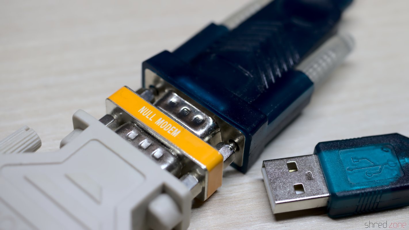
On the hardware side, you will need a construction with a DB25 female port on the one end, and an USB connector on the other end. I use one of those USB-to-Serial converters that can be found on hardware shops for little money. They are often equipped with a DB9 male connector, and are supposed to be connected to peripheral devices (like modems). To connect them to a computer, a so-called zero modem (or null modem) is required, which is just a small adapter that enables to connect two computers directly together by crossing the transmit and receive lines. Finally, we need a DB9-to-DB25 connector with the correct genders, to connect the other end of the zero modem to the Amiga.
This hardware stack is connected to the Amiga's serial port on the one end, and to a USB port of the PC on the other end. Remember to turn off the Amiga before connecting something to the serial port. Unlike USB, the ports of old computers are not designed for connecting or disconnecting devices while the system is powered. It could actually damage the system to do so!
On the software side, we don't need to install drivers on the Amiga. The debug or diagnostics output is just sent to the serial port. On Linux, we can use any terminal emulator. The most prominent is certainly minicom.
The default serial port settings are 9600-8N1 (9,600 bps, 8 bits per character, no parity, 1 stop bit). However, the debug output is just directly sent to the serial port. If you changed the serial parameters on Amiga side, and used the serial.device for something else, the debug output will use the current settings. Handshake must be turned off in any case, though.
Maybe the easiest way is to create a file called ~/.minirc.amiga with the following content (change the pu port value to your actual TTY USB device):
pu port             /dev/ttyUSB0
pu baudrate         9600
pu bits             8
pu parity           N
pu stopbits         1
pu rtscts           No
pu xonxoff          No
On many Linux distributions, the user also needs to be added to the dialout group in order to access a serial device:
sudo usermod -aG dialout $(whoami)
After that, just start minicom with the amiga profile:
minicom amiga
Now you should see all the debug output generated by AmigaOS on your minicom screen. For interactive debuggers like ROMWack, you can also type commands into the console.
To leave minicom, press CTRL-A and then Q. 😉
Amiga CD32
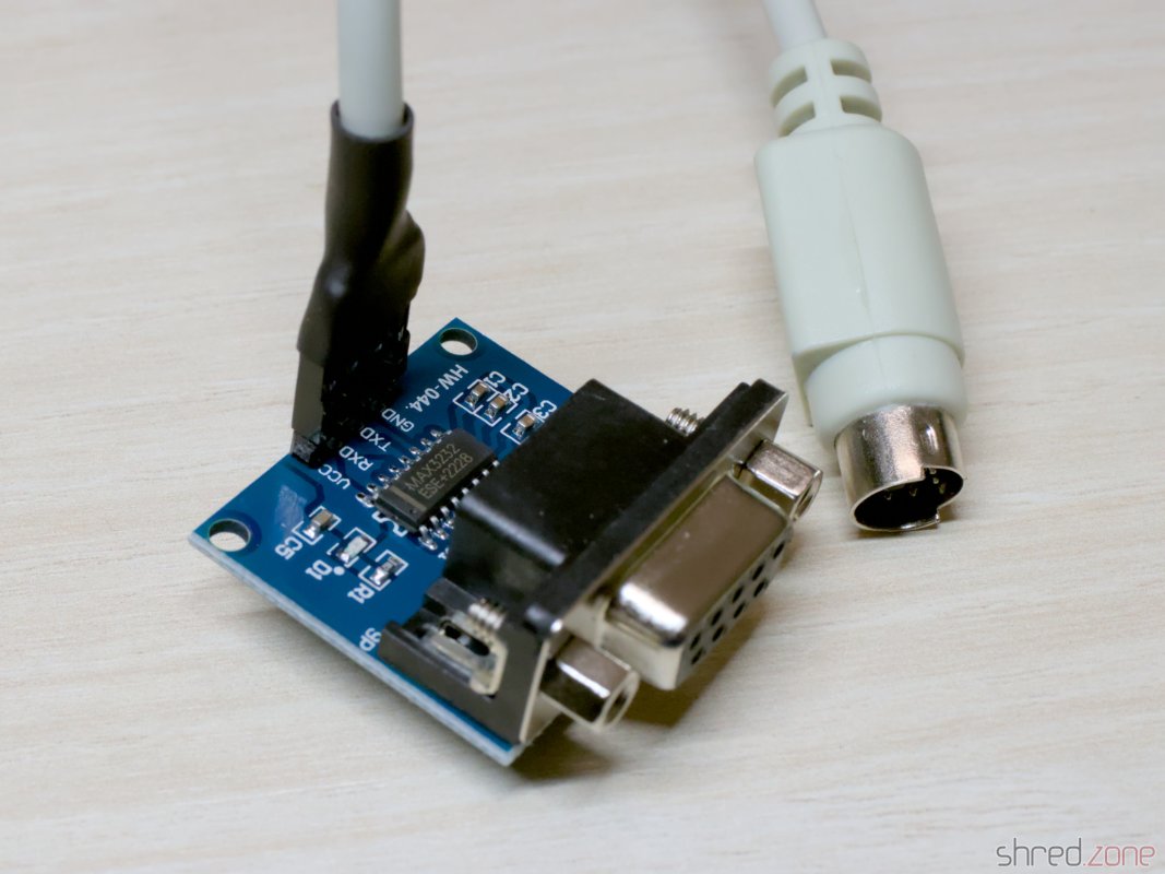 Unlike other Amiga models, the CD32 has no dedicated RS-232 port. Instead of that, it provides a simple serial interface at the Aux port that is connected to Paula's UART pins internally.
To build an adapter, you need a PS/2 cable (e.g. from an extension cord or an old PS/2 input device) and a MAX3232 based TTL-to-DB9 level converter. These converters can be found at online marketplaces for a few Euro.
Cut one end of the cable and connect the wires to the converter like that:
- Pin 2: TXD
- Pin 3 (and the shield): GND
- Pin 4: VCC
- Pin 6: RXD
Leave the remaining two wires unconnected, and check for correct polarity before connecting the wires to the converter!
The CD32 does not provide any control and handshake signals, but fortunately they are not needed for debugging and diagnostics purposes.