In the previous part, I refurbished the keyboard of the Amiga 1000. It was in a bad state, and truly deserved to get its own part. Now I will replace the floppy drive with a Centuriontech GOEX on pills floppy simulator, and then put everything back together.
Floppy LED
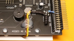
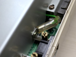
The floppy LED of the Amiga 1000 is not connected to the mainboard, but to the floppy drive. The GOEX drive does not provide a similar connector, so I had to come up with a solution. Fortunately, the Amiga made it faily easy.
On all Amiga models, the floppy LED represents the state of the drive motor. It lights up as long as the motor is powered. On the Amiga 1000, the motor of the internal drive is controlled by a /MTR0 signal on pin 16 of the floppy connector. If it is LOW, the motor is powered, and the floppy LED is supposed to light up. The 7438 buffer inside the Amiga has a maximum output current of 48mA, while the LED has a forward current of 30mA, so in theory the LED (and a 120Ω series resistor) could be connected directly to the /MTR0 line and +5V. But I wanted to be on the safe side, so I added an inverting switch using a standard PNP transistor and two resistors.
I used a BC557, but any other standard switching PNP transistor will do as well. For the LED, I preferred to have a green floppy LED instead of the original red one. I used a Dialight 521-9266, which has the same dimensions as the original LED. There should be a pullup resistor on the /MTR0 line, but it's also working without, so on my system I left it out for space reasons.
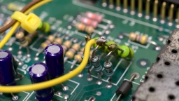
On the GOEX board, +5V can be found on an unused pad next to the voltage regulator. GND can be found at an unused header for an optional encoder.
On Screen Display
The GOEX drive needs some kind of display, to show the floppy disk file that is currently selected, and other options. My first plan was to glue a tiny OLED display to the front of the case.
However, the "GOEX on pills" model comes with an OSD connector. It reads the CSYNC signal from the Amiga, and generates a pixel signal that is overlaid to the Amiga RGB signal. Depending on the color component the pixel signal is connected to, the OSD text is either red, green, or blue (with the corresponding complementary color as background).
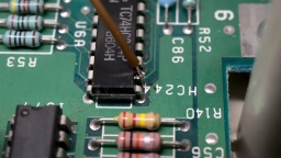
The CSYNC signal can be taken from pin 12 of U6A. The pixel signal is connected to one of the 75Ω resistors: R25 (red), R24 (green), or R23 (blue). The wire must be soldered to that end of the resistor that is closer to the monitor connector, otherwise the OSD overlay will not be visible on white screens.
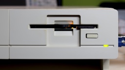
The other end of the two wires are connected to the respective CSYNC and RGB pins of the OSD header of the GOEX drive. It is also possible to control the GOEX drive with the Amiga keyboard, but I didn't want to do more hardware modifications, especially if it involves soldering wires directly to one of the CIAs. I prefer that I still have to touch the floppy slot for changing floppy disks, even if it's just virtually.
Reassembly
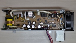
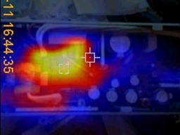
A trained technician should definitely overhaul the PSU, to avoid damage to the hardware or spectacular explosions of safety capacitors. @DingensCGN of the a1k.org forum did an excellent job there. He replaced all electrolytic capacitors, and did a full load test including checking the temperatures of the components with a thermographic camera. A big shout-out to him!
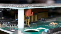
This Amiga has a separate piggyback board, which I had removed for cleaning and re-capping. It is connected to the mainboard by some headers at different places, which makes reseating it a bit tricky. It is crucial that all headers are properly connected.
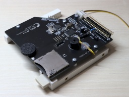
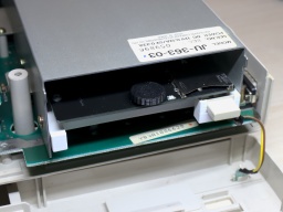
For the GOEX drive, I designed a 3D printed frame for the Amiga 1000. It holds the drive in its correct position, and also holds the original eject button so the hole in the front is closed. My intention is that the GOEX drive should be as invisible as possible, so the original look of the Amiga 1000 is maintained. I guess I managed that.
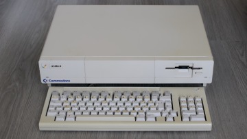
And that's it. The system is fully assembled now.
I mounted the top shield, attached the front plate, closed the case, and connected the 256KB memory expansion to the front slot.
And then came the moment of truth. I flipped the power switch. The system started up. I expected the 230V PSU fan to be rather noisy, and was very surprised that it is almost inaudible, and could easily compete with modern ultra-silent 12V fans of the same size.
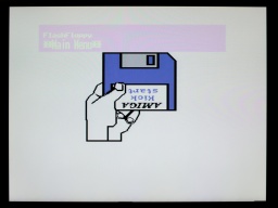
Then the famous Kickstart screen appeared, together with the FlashFloppy OSD.
I loaded the Kickstart ADB file from the GOEX drive, and after that I changed to the first disk of the famous Red Sector Megademo. The Amiga just dutifully loaded it.
Everything ran smoothly! The green color of the OSD certainly adds a lot to the 1980s retro feeling of that machine. It looks quite like those OSDs on old TVs or VCRs. 😆
Configuring FlashFloppy
There were two things that were bugging me. The first was that I'd like to run a cold start of the machine as simple as possible, so the GOEX drive should always select the Kickstart ADF first when the system is powered up. The second was that the OSD was shown on the screen for much too long. It should disappear a few seconds after disk inactivity.
Both is easily configured. First, a directory called FF needs to be created on the SD card. Then a FF/FF.CFG file needs to be created, having this content:
image-on-startup = static
display-off-secs = 5
A second file called FF/IMAGE_A.CFG contains the file name of the Kickstart ADF file on the SD card.
Welcome!
And that's it! I am, and have always been, a big fan of the Amiga. I learned a lot on my Amigas, and they were the foundation of my career as professional software developer.
I always considered the Amiga 1000 to be the pearl of my Amiga collection, and I am happy and proud that I got the chance to own such a beautiful machine now.
