Coking Plant, Zeche Zollverein, Essen

#A1000-restauration

Amiga 1000 Restauration, Part 3

In the previous part, I refurbished the keyboard of the Amiga 1000. It was in a bad state, and truly deserved to get its own part. Now I will replace the floppy drive with a Centuriontech GOEX on pills floppy simulator, and then put everything back together.

Floppy LED

The floppy LED of the Amiga 1000 is not connected to the mainboard, but to the floppy drive. The GOEX drive does not provide a similar connector, so I had to come up with a solution. Fortunately, the Amiga made it faily easy.

On all Amiga models, the floppy LED represents the state of the drive motor. It lights up as long as the motor is powered. On the Amiga 1000, the motor of the internal drive is controlled by a /MTR0 signal on pin 16 of the floppy connector. If it is LOW, the motor is powered, and the floppy LED is supposed to light up. The 7438 buffer inside the Amiga has a maximum output current of 48mA, while the LED has a forward current of 30mA, so in theory the LED (and a 120Ω series resistor) could be connected directly to the /MTR0 line and +5V. But I wanted to be on the safe side, so I added an inverting switch using a standard PNP transistor and two resistors.

SVG Picture created as drive-led.svg date 2022/10/31 09:06:35Picture generated by Eeschema-SVG+5V+5V10K10K1M1MBC557BC557Drive LEDDrive LED120R120R~{MTR0}~{MTR0}161610K10KBC557BC557Drive LEDDrive LED120R120RSVG Picture created as drive-led.svg date 2022/10/31 09:06:35

I used a BC557, but any other standard switching PNP transistor will do as well. For the LED, I preferred to have a green floppy LED instead of the original red one. I used a Dialight 521-9266, which has the same dimensions as the original LED. There should be a pullup resistor on the /MTR0 line, but it's also working without, so on my system I left it out for space reasons.

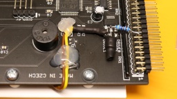
On the GOEX board, +5V can be found on an unused pad next to the voltage regulator. GND can be found at an unused header for an optional encoder.

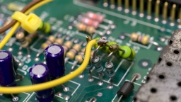
The base resistor is connected straight to pin 16 of the header. +5V can be taken from a pad next to the voltage regulator. GND is available at the unused encoder header. A bit of hot glue fixes the wires to the board. I replaced the original red floppy LED with a green one, just because I like it better. 😉

On Screen Display

The GOEX drive needs some kind of display, to show the floppy disk file that is currently selected, and other options. My first plan was to glue a tiny OLED display to the front of the case.

However, the "GOEX on pills" model comes with an OSD connector. It reads the CSYNC signal from the Amiga, and generates a pixel signal that is overlaid to the Amiga RGB signal. Depending on the color component the pixel signal is connected to, the OSD text is either red, green, or blue (with the corresponding complementary color as background).

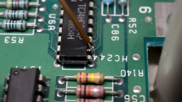
The CSYNC signal can be taken from pin 12 of U6A. The pixel signal is connected to one of the 75Ω resistors: R25 (red), R24 (green), or R23 (blue). The wire must be soldered to that end of the resistor that is closer to the monitor connector, otherwise the OSD overlay will not be visible on white screens.

The CSYNC signal is taken from U6A pin 12. The RGB signal is connected to R24 for a green OSD color.

The other end of the two wires are connected to the respective CSYNC and RGB pins of the OSD header of the GOEX drive. It is also possible to control the GOEX drive with the Amiga keyboard, but I didn't want to do more hardware modifications, especially if it involves soldering wires directly to one of the CIAs. I prefer that I still have to touch the floppy slot for changing floppy disks, even if it's just virtually.

Reassembly

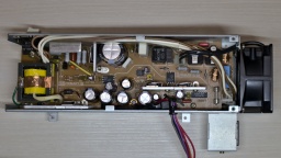
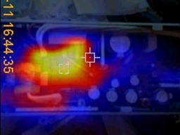
A trained technician should definitely overhaul the PSU, to avoid damage to the hardware or spectacular explosions of safety capacitors. @DingensCGN of the a1k.org forum did an excellent job there. He replaced all electrolytic capacitors, and did a full load test including checking the temperatures of the components with a thermographic camera. A big shout-out to him!

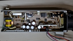
The PSU was overhauled by @DingensCGN at a1k.org. Result of the thermographic camera check: The load resistors are getting rather hot, but that's normal. The other components stay cool.

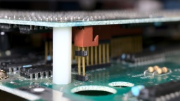
This Amiga has a separate piggyback board, which I had removed for cleaning and re-capping. It is connected to the mainboard by some headers at different places, which makes reseating it a bit tricky. It is crucial that all headers are properly connected.

The piggyback board must be carefully reconnected.

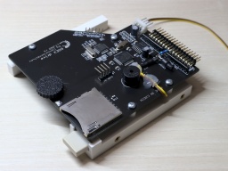
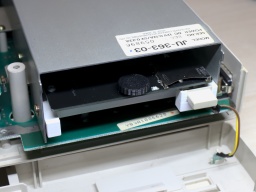
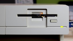
For the GOEX drive, I designed a 3D printed frame for the Amiga 1000. It holds the drive in its correct position, and also holds the original eject button so the hole in the front is closed. My intention is that the GOEX drive should be as invisible as possible, so the original look of the Amiga 1000 is maintained. I guess I managed that.

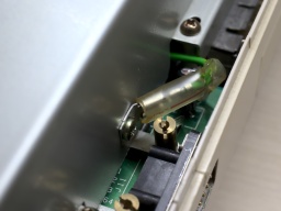
GOEX drive on the Amiga 1000 mounting frame. The best place I could find for the grounding. The GOEX drive inside the Amiga floppy frame.

And that's it. The system is fully assembled now.

The fully reassembled system.

I mounted the top shield, attached the front plate, closed the case, and connected the 256KB memory expansion to the front slot.

And then came the moment of truth. I flipped the power switch. The system started up. I expected the 230V PSU fan to be rather noisy, and was very surprised that it is almost inaudible, and could easily compete with modern ultra-silent 12V fans of the same size.

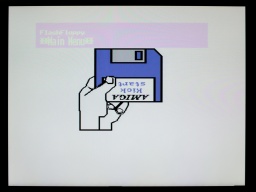
Then the famous Kickstart screen appeared, together with the FlashFloppy OSD.

The famous Kickstart screen, with the magenta OSD from the GOEX drive.

I loaded the Kickstart ADB file from the GOEX drive, and after that I changed to the first disk of the famous Red Sector Megademo. The Amiga just dutifully loaded it.

Red Sector Megademo is loading, here with green OSD because of the dark background.

Everything ran smoothly! The green color of the OSD certainly adds a lot to the 1980s retro feeling of that machine. It looks quite like those OSDs on old TVs or VCRs. 😆

Configuring FlashFloppy

There were two things that were bugging me. The first was that I'd like to run a cold start of the machine as simple as possible, so the GOEX drive should always select the Kickstart ADF first when the system is powered up. The second was that the OSD was shown on the screen for much too long. It should disappear a few seconds after disk inactivity.

Both is easily configured. First, a directory called FF needs to be created on the SD card. Then a FF/FF.CFG file needs to be created, having this content:

image-on-startup = static
display-off-secs = 5

A second file called FF/IMAGE_A.CFG contains the file name of the Kickstart ADF file on the SD card.

Welcome!

And that's it! I am, and have always been, a big fan of the Amiga. I learned a lot on my Amigas, and they were the foundation of my career as professional software developer.

The fully restaured Amiga 1000.

I always considered the Amiga 1000 to be the pearl of my Amiga collection, and I am happy and proud that I got the chance to own such a beautiful machine now.
Amiga 1000 Restauration, Part 2

In this second part, I will take care about the keyboard. I expected that it would be the usual procedure: Cleaning the key caps and case, whitening the yellowed parts, dusting off the keyboard frame.

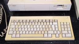
The Amiga 1000 keyboard, before cleaning and whitening.

However, this time it wasn't that easy.

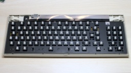
The trouble started when I pulled off the key caps, but also pulled out the plungers of three keys. Fortunately this can be repaired, as the switches are easy to maintain. More about that below.

Keyboard Cleaning

The key caps were cleaned in an ultrasonic bath with a drop of rinse aid, and then brushed with a soft toothbrush.

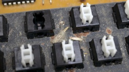
Below the key caps, there is the keyboard frame where the switches are mounted. I found the usual filth that you would expect there after almost 40 years, but there was also flash rust, a crusty dirt layer, and… dead insects. I went outside and brushed off the insects and all the other loose dirt. Then I went back inside, and sprayed the frame with IPA, in an attempt to clean off the crust. The room immediately filled with an unhealthy stench of dust, dirt, and insect excrements. 🤢 Also, my attempts to remove the flash rust with a fiberglass pen wasn't really successful. There was too much of it.

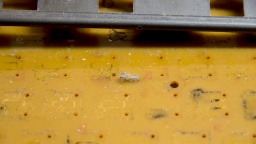
Yuck! Rust, crusty filth, and dead insects. My attempts to clean the frame in place were futile.

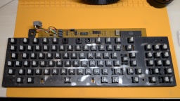
I wanted to avoid that I had to refurbish the frame, because it can only be removed after unsoldering all 91 switches (and one LED). But there was no other way to do it. So I unsoldered everything and removed the frame. On the PCB, I found dried stains from a liquid (maybe from a soft drink that had been spilled over the keyboard), and more dead insects. It confirmed that it was the right choice to go all the way.

Under the frame I found liquid stains, and more insects.

I sanded down the old paint and the dirt crust from the frame (outside, and wearing a good filter mask). Then I spray-painted it in a matte black. It's looking so much better now.
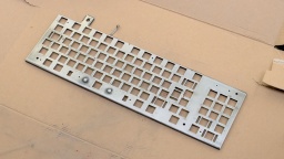
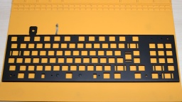
The frame, after sanding it. Freshly painted with matte black spray paint.

Refurbishing the Switches

The next bad surprise came when I was about to reassemble the keyboard. I tested all 91 switches for continuity when closed, but found only about 40 of them actually working. When I depressed the other keys, they either did not close the contact, or the plunger got stuck, or both.

The switches that are used in the Amiga 1000 keyboard are Mitsumi Type 2 tactile switches. They are out of production by today, but they are easy to maintain. After trying the best approach with a couple of switches, I found the following procedure to be most successful.

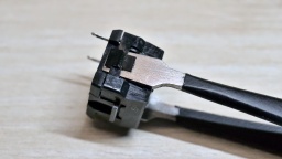
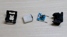
The switch can be opened by putting a kind of blade (like the head of a flat screwdriver, or flat pincers) into the latch on both sides, and then carefully removing the cap with a blade or another screwdriver. The switch consists of four parts: The cap, the plunger, the switch plate, and the base.

Insert a screwdriver or pincers, then carefully pull the cap from the base. From left to right: Cap, plunger (with spring), switch plate (with metal lever), base.

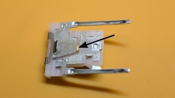
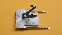
I cleaned the switch plate with contact cleaner spray. I also bent up the legs of the lever a tiny bit, so it will give a bit more pressure on the switch when the key is depressed.

Spray a bit of contact cleaner on the copper part in the center. If the contact does not close properly after cleaning, bend up the legs of the lever a tiny bit.

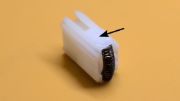
Finally, I applied a bit of silicone grease on both small sides of the plunger. It is important to use a very very tiny amount! If too much is used, the key will feel sluggish or might even get stuck. If in doubt, better skip this step.

Apply a very tiny amount of silicone grease on the bottom half of the small plunger sides.

After that, the switch was reassembled and tested again. If it was still getting stuck or didn't close the contact properly, the process was repeated.

It was a lot of work and a monotonous task, but at the end I could make all the switches work again.

Cleaned and refurbished keyboard, before putting on the keycaps.

Whitening

The keyboard case was cleaned in soap water. After that, the case (and the yellowed space bar) were exposed to the July sun for whitening.

The result is quite good, but on some parts a bit of yellow is still visible. I guess there would be an even better result if I would use peroxide, but I have no experience with that, and am not too keen to gain it with this rare keyboard.

The labels on some of the keys are still yellow, and wouldn't get any whiter in the sun. I guess that I will have to replace them with new labels some day.

Reassembling

With every parts cleaned and whitened, the keyboard was ready for reassembly. I pressed the key caps back on the keys, mounted the shielding, and then put the keyboard frame back into the case.

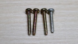
Take care when closing the case: One of the four screws is a bit shorter, and maybe also has a different color. This single screw must be used for the upper right hole.

One case screw is shorter, and has a different color. Use the shorter screw for the hole at the top right.

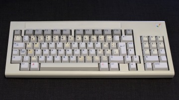
The keyboard restauration is completed now!

The Amiga 1000 keyboard is completed.

In the next part, I will reassemble the main unit, and have a first test. Is the Amiga still working?

Amiga 1000 Restauration, Part 1

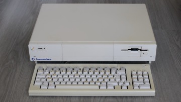
When the Amiga 1000 was launched in 1985, it was too expensive as a home computer, but rather targeted the professional graphics workstation market. The sales figures were correspondingly low. Only 27,500 units have been sold in Germany. Nevertheless, and without a doubt, the Amiga 1000 is the jewel of every Amiga collection. Now I finally had the lucky chance to get my own one.

The Amiga 1000, as I got it. The keyboard is a French/Belgian AZERTY type, with labels for the German keyboard layout.

The overall state is fine, considering that the machine is almost 40 years old. The Amiga itself is only a bit yellowed, but has some heavy scratchmarks at one edge. The keyboard has a French/Belgian AZERTY layout that was changed to German layout using stickers, like it was usual for the first machines that were sold in the EU. Its case and the space bar are much more yellowed. The stickers are also yellowed, and one is missing.

The expansion slot at the front contains a 256KB RAM module. The original mouse and the disks have been lost, but I can use any other Amiga mouse and make new disks myself.

What's Inside

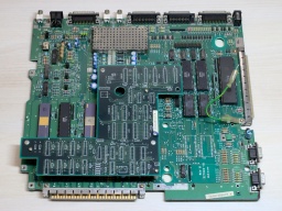
Inside I found a Rev A mainboard and a piggyback board. That extra board stores the Kickstart that is loaded from disk when the machine is powered up. Later revisions used Kickstart ROMs, and didn't need this piggyback board any more.

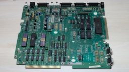
The mainboard, and the piggyback board on top.

Usually all piggyback Amiga 1000 were produced for the US market. They could not run in Europe without modifications, due to different power frequencies and TV standards. My machine was produced in early 1986, presumably for the US market. One year later, it was modified for the European market. The original Agnus chip was replaced by a 8367R0 that is able to generate PAL video signals. The crystal is still the original 28.6363 MHz NTSC one though, so the video signal is not truly PAL.

The system has a Denise 8362R6, which is the first revision that is also capable of displaying the EHB mode.

Altogether, it is an early Amiga model, and very likely one of the first that have been sold in Germany.

The PSU

Generally I don't recommend to power up an old computer straight away after many years of storage. Without a visual inspection and the necessary refurbishment, the power supply could damage the computer, or components inside could blow up.

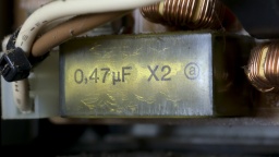
A first visual check of the PSU seemed to be allright, with no obvious damages, and no bulged or leaked capacitors. But then I found tiny cracks in one safety capacitor.

A look into the PSU. This RIFA capacitor shows signs of fatigue.

These RIFA X class capacitors are actually infamous for blowing up after many years. Their insulators are made from paper. The material gets brittle from age and thermal stress, letting in moisture, which amplifies the problem. Eventually the capacitor can crack open and go up in fumes.

It was good that I kept the PSU disconnected from mains. It is now being refurbished by @DingensCGN, a member of the A1K.org forum who has a lot of experience with Amiga PSU restauration.

The Mainboard

I recapped the mainboard and piggyback board. For the seven 22µF capacitors, I used a bipolar type instead. Those capacitors are used for filtering the audio and RGB signals. Using bipolar caps here might improve the signal quality, and won't hurt otherwise.

To be honest, this time I had doubt if I should replace the old capacitors. This Amiga 1000 will not become a workstation, I have other Amigas for that. It is rather a collectible. Still I want it to be in a good technical condition. When I started to collect retro computers, I promised myself not to keep machines that are broken or otherwise not fit for use.

After that I removed all the dust, and gave the boards a thorough wash with IPA.

The mainboard, with fresh electrolytic capacitors.

The mainboard is now ready to get remarried with the piggyback board, and then move back into the case.

Whitening

The first thing I actually did was to disassemble the entire machine. The plastic parts of the case were cleaned in soap water and carefully scrubbed with a dishwashing brush. After that, I used the sunny July weather, and whitened all parts in the sunshine. I did not use any chemicals, just the sun. After two days, the Amiga was almost white again.

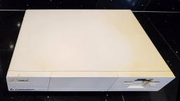
All case parts are whitened and ready for reassembly.

That's it for the first part of the Amiga 1000 story. The next part will be about the restauration of the keyboard. There is a lot to do there.