Premium Wall Bias Lighting, Part 1

A good way to relieve the strain from your eyes while working on a PC, is to illuminate the wall behind your monitor. Jason Fitzpatrick wrote an interesting article about what bias lighting is and why you should be using it.

Many light sources can be used as bias lighting. I have used an old bedside lamp for a while. But what about something more stylish? What about a LED strip on an aluminum profile?

In this project, I am going to make a Wall Bias Lighting myself, and write a controller software for it. The source code will be released on my GitHub profile eventually, so you will be able to customize it.

Proof of Concept

To make it a true premium lighting, I use a LED strip that consists of SK6812 RGBW LEDs. It can produce colors, but it also has separate white LEDs for a clean neutral white. Even better: Each LED can be addressed and the color changed individually. It would be possible to illuminate the wall behind the monitor in a bright white, while the visible parts of the strip are in a soft blue that won't dazzle the eyes.

AdaFruit sells these LED strips under their brand name NeoPixel, but there are also no-name strips on the market that are fully compatible and considerably cheaper. The strips are usually sold on reels of up to 5 meters length. They can be shortened to the desired size with scissors, and have an adhesive tape on the back so they can be glued to aluminum profiles.

This is the bill of material for the first proof-of-concept phase of the project:

  • An SK6812 RGBW LED strip with 60 LEDs per meter
  • An aluminum wall profile for LED strips
  • 1x AdaFruit Feather M0 Express
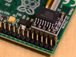
  • 1x Level converter (read below)
  • 1x 1000 µF/16 V capacitor, 1x 500 Ω resistor (read here why they are needed)
  • 1x 5 V power brick. Each LED is said to consume up to 60 mA (I couldn't find concrete figures), so you will need 18 W per strip meter if you want to set all four colors of all LEDs to maximum brightness.

The assembly was rather simple. First I cut the profile and the strip to the desired length and glued them together. Then I connected the strip to the power supply, and the strip's data line to the Feather via the level converter.

The next thing on the to-do list was a quick test drive, to check if some of the LEDs are defective. So I installed CircuitPython on the Feather, and wrote a tiny test program that just cycles through the colors red, green, blue, and white. With this pattern, even a single defective LED would immediately catch one's eye.

I turned on the power supply, aaaand... Nothing! 😲 All the LEDs stayed black.

I checked and double checked the wiring, but everything seemed to be correct. I tested my test program on the single NeoPixel that is mounted on the Feather, and it worked there.

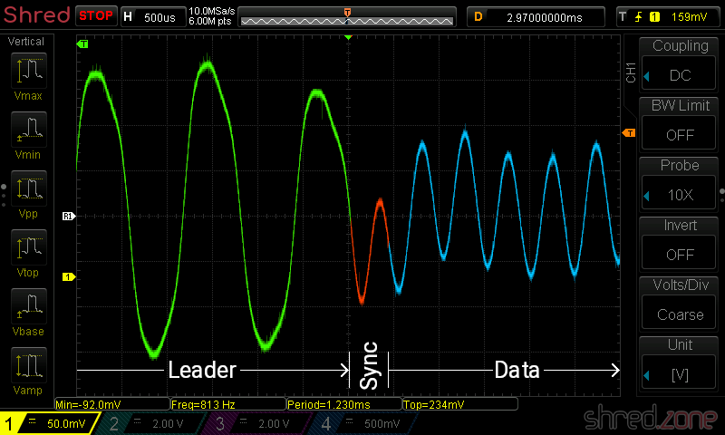
Puzzled, I connected my scope to the data line of the LED strip. It immediately revealed the culprit.

The Feather runs on 3.3 V, and so the signal on the data line has an amplitude of 3.3 V.

The LED strip runs on 5 V though, and also expects a signal amplitude of 5 V. The logic converter between the Feather and the strip is supposed to convert the 3.3 V signal to 5 V. However, the BSS138 based bi-directional logic level converter from my spare part box turned out to be too slow for this purpose. The output level starts at 3 V and then ramps up to 4 V.

This is not sufficient for the SK6812, which needs a 5 V signal and a very precise timing with clean signal edges. Both was not given, so the LEDs stayed black.

I replaced the logic level converter by a standard 74HCT125 buffer IC, and tried again. The LED strip immediately came to life and cycled through the colors. The scope now shows a clean (well, more or less clean) 5 V signal.

My proof-of-concept is working. 🎉 This is what the circuit looks like:

While the LED strip is powered by the power brick, the Feather is going to be powered by USB as long as I am developing the software. Later I will also supply the Feather with LED power, so it runs stand-alone.

Never connect the Feather to an USB port while it is supplied by an external power source. It could damage your computer.

What next? I'm going to add a power button, so I can turn the light on and off. For controlling the brightness and light effects, I am also going to add a display, a rotary switch, and another button. Stay tuned…

Kompakt und leise

ASRock DeskMini A300 Kompakt, schnell und leise ist eine Herausforderung beim Selbstbau eines PCs. Meistens bekommt man nur zwei dieser Eigenschaften auf Kosten der dritten. Ich habe mich trotzdem an einen Versuch gewagt.

Das Ergebnis ist:

  • Gehäuse und Mainboard: Das ASRock DeskMini A300 ist ein Barebone, das kaum größer ist als ein ATX-Netzteil. Trotzdem hat es genug Platz für einen Prozessor mit AM4-Sockel und einer Verlustleistung von bis zu 65 Watt. Dazu passen zwei 2,5-Zoll-Festplatten und zwei M.2-SSDs hinein. WLAN gibt es optional dazu. Versorgt wird das Gerät mit einem externen 300W-Notebook-Netzteil.
  • Kühlung: Ich verzichtete auf den beigelegten Kühlkörper und baute ein Noctua NH-L9a-AM4 ein. Die Lüfter- und Kühlkörper-Lösung ist wie für dieses Gehäuse gemacht. Der Lüfter ist enorm leise. Selbst unter Last ist nur ein leises Rauschen zu hören, das überhaupt nicht stört.
  • CPU: Hier setzte ich auf einen AMD Ryzen 5 2400G, welcher sich bereits in meinem PC unter Linux bewährt hat. Mit 65 Watt TDP passt er in das Gehäuse und bietet mehr aus ausreichend Leistung für Office-Anwendungen, Video-Streaming und einfache Games.
  • RAM: 8 GB DDR4-2400 SO-DIMM als Kit mit 2x 4 GB. Für den gedachten Anwendungszweck reicht das. Bei einer Bestückung beider Slots mit Dual Rank-Modulen ist bei 2400 MHz Schluss, so dass der Kauf höher getakteter Speicherriegel nur Geld verschwendet hätte.
  • SSD: Als Festspeicher wurde eine vorhandene 2,5-Zoll SATA-SSD weiter verwendet.

Das System ließ sich zügig zusammenbauen. Problematisch war lediglich die Montage des Noctua-Kühlers. Dafür muss die vorhandene Halterung samt Bodenplatte entfernt werden. Anschließend wird Wärmeleitpaste auf die CPU aufgetragen, der Kühler daraufgelegt und von unten auf die beigelegte Bodenplatte geschraubt. Es erfordert schon ein wenig Geschick, den Kühlkörper dabei so wenig wie möglich zu bewegen, um die Wärmeleitpaste nicht zu verschmieren. SATA-Festplatten werden mit einem Spezialkabel mit dem Mainboard verbunden. Auch hier war es ein wenig Fummelei, den Spezialstecker auf das Mainboard zu stecken.

Bei einem ersten Test bootete ein Fedora 29-Livesystem auf der Maschine. Nachdem ich aber das BIOS auf die aktuelle Version 3.40 aktualisiert hatte, verweigerte das Livesystem selbst im Kompatibilitätsmodus den Dienst. Erst Fedora 30 (welches derzeit noch im Beta-Stadium ist) bootete problemlos und ließ sich ebenso leicht installieren.

Das System arbeitet unter Fedora 30 einwandfrei und stabil, selbst mit zwei angeschlossenen Monitoren. Beeindruckt hat mich vor allem der ruhige, nahezu lautlose Betrieb, der trotz dieser kompakten Abmessungen möglich ist. Darüber hinaus lässt sich ein solches System für einen verhältnismäßig günstigen Preis zusammenbauen. Es eignet sich bestens als kompakter Schreibtischrechner oder anspruchsvoller HTPC.

Fluido skin and Markdown syntax highlighting

doxia-module-markdown is a Maven plugin that enables Markdown in Maven documentations. In version 1.8, the developers have moved from Pegdown to Flexmark as Markdown parser. It's a good choice, as Flexmark is considerable faster and is still being maintained, while Pegdown officially reached its end of life in 2016.

However, with that switch, code blocks are not syntax highlighted any more. The reason is that the maven-fluido-skin uses code-prettify for syntax highlighting. It runs browser-side, highlighting all <pre> and <code> blocks selecting the prettyprint CSS class. This was true with Pegdown, but Flexmark selects a source class instead.

An obvious workaround is to use a small JavaScript snippet that adds a prettyprint class to all blocks selecting a source class, and then running prettyPrint() again. To do so, this block needs to be added to the <head> section of site.xml:

<head>
  <!-- Workaround for https://issues.apache.org/jira/browse/DOXIA-571 -->
  <![CDATA[<script type="text/javascript">
    $(document).ready(function () {
      $(".source").addClass("prettyprint");
      prettyPrint();
    });
  </script>]]>
</head>

It's hard to tell if this is a bug in doxia-module-markdown or in maven-fluido-skin. Also see my bug report at Apache's JIRA.


This was a Google Plus comment that I have now moved to my blog as Google Plus is going to be closed. Thanks to Clement Escoffier for the inspiration.

Z80 Disassembler

Some days ago, I was adding a Z80 disassembler to my tzxtools. I could not find one for Python, so I decided to write my own. The result fits into a single Python source file. This article is the Making-of…

The Zilog Z80 is an 8 bit processor. This means that (almost) all instructions only consume 1 byte. For example, the instruction ret (return from subroutine) has C9 as byte representation. Some commands are followed by another byte (as a constant to be used, or a relative jump displacement) or another two bytes (as a 16 bit constant or absolute address). Some examples:

C9------retReturn from subroutine
3E23----ld a,$23Load constant $23 into A register
C33412--jp $1234Jump to address $1234

Note that for 16 bit constants, the bytes seem to be reversed in memory. This is because the Z80 is a so-called little endian CPU, where the lower byte comes first. Some other processor families (like the 68000 ) are big endian and store the higher word first.

So there are 256 instructions only, which makes it pretty easy to disassemble them. I used an array of 256 entries, where each entry contains the instruction of the respective byte as a string. For constants, I have used placeholders like "##" or "$". If such a placeholder is found in the instruction string after decoding, the appropriate number of bytes are fetched, and the placeholder is replaced by the value that was found.

If we were to write a disassembler for the 8080 CPU, we were done now. However, the Z80 has some extensions that need to be covered, namely two extended instruction sets and two index registers.

One set of extended instructions is selected by an $ED prefix, and contains rarely used instructions. The other instruction set is selected by a $CB prefix and has bit manipulation and some rotation instructions.

EDB0----ldirCopy BC bytes from HL to DE
ED4B7856ld bc,($5678)Loads value from address $5678 into BC register pair
CBC7----set 0,aSet bit 0 in A register

For the $ED prefix, I used a separate array for decoding the instructions. The $CB instructions follow a simple bit scheme, so the instructions could be decoded by a few lines of Python code.

The Z80 provides two index registers, called IX and IY. They are used when the instruction is prefixed with a $DD or $FD byte, respectively. These prefixes basically use the selected index register instead of the HL register pair for the current instruction. However, if the (HL) addressing mode is used, an additional byte sized offset is provided. The index registers can be combined with the $CB prefix, which can make things complicated.

E5------push hlPush HL to stack
DDE5----push ixPush IX to stack (same opcode E5, but now with DD prefix)
FDE5----push iyPush IY to stack (now with FD prefix)
FD2180FFld iy,$FF80Load $FF80 constant into IY register
DD7E09--ld a,(ix+9)Load value at address IX+9 to A register (offset is after opcode)
CBC6----set 0,(hl)Set bit 0 at address in HL
FDCB03C6set 0,(iy+3)Set bit 0 at address IY+3 (offset is before opcode)

When the disassembler detects a $DD or $FD prefix, it sets a respective ix or iy flag. Later, when the instruction is decoded, every occurance of HL is replaced by either IX or IY. If (HL) was found, another byte is fetched from the byte stream and used as index offset for (IX+dd) or (IY+dd).

There is one exception. The examples above show that the index offset is always found at the third byte. This means that when the index register is combined with a $CB prefix, the actual instruction is located after the index. This is a case that needed special treatment in my disassembler. If this combination is detected, then the index offset is fetched and stored before the instruction is decoded.

Phew, this was complicated. Now we’re able to disassemble the official instruction set of the Z80 CPU. But we’re not done yet. There are a number of undocumented instructions. The manufacturer Zilog never documented them, they are not quite useful, but they still work on almost any Z80 CPU and are actually in use.

Most of them are covered just by extending the instruction arrays. Additionally, the $DD or $FD prefixes do not only affect the HL register pair, but also just the H and L registers, giving IXH/IYH and IXL/IYL registers. This is covered by the instruction post processing. A very special case is the $CB prefix in combination with index registers, giving a whole bunch of new instructions that store the result of a bit operation in another register. This actually needed special treatment by a separate $CB prefix instruction decoder.

Finally, the ZX Spectrum Next is going to bring some new instructions like multiplication or ZX Spectrum hardware related stuff. They were again covered by extending the instruction arrays. The only exceptions are the push [const] instruction where the constant is stored as big endian, and the nextreg [reg],[val] instruction that is (as the only instruction) followed by two constants.

And that’s it. 😄 This is how to write a Z80 disassembler in a single afternoon.

Shredzone à la Amiga

Look what I have found... This is my very first shredzone, as it was online from 1998 to 2003. First it was hosted by my internet provider. Then, on April 15th 2000, I registered my own domain – shredzone.de – and moved my site to a professional hoster.

The site did not use a fancy content mangagement system, but consisted only of static HTML pages. It was built on my Amiga using a preprocessor called HSC, an acronym for HTML Sucks Completely. 😜 Some parts like the gallery or the download area were generated by accompanying ARexx scripts. It was incredibly easy to add content to the site. Basically it was just adding or changing a file, and then invoking smake to rebuild the affected parts of the site within seconds, including the navigation. It was a big advantage that I was going to miss badly later.

At that time I did not use CVS yet, so sadly all the past versions and changes have been lost. The only version I still have is the final one on my Amiga harddisk. I have found the project today, by a rather lucky accident. It was only the source code though, the final compiled version has got lost over the years. There is a Linux port of HSC, so basically I could rebuild the site on my Linux machine. But the ARexx parts require an Amiga environment, and porting them to Linux would have consumed too much time.

So I started an Amiga emulator and, thanks to the good shape of the project that the past Amiga me has left the present Linux me, I actually only needed to run smake to rebuild the entire homepage in just 3 minutes.

The requirement to run on an Amiga, was what later broke the neck of this homepage. When the Amiga platform died, I moved on to Linux, but I could not move my homepage with me. So, in 2003, I replaced it with a self-made content management system that was written in PHP and was called Akiko. It had some nice features, but on the other hand it was rather tedious to add new content. Because of that, I badly neglected my homepage in those years.

In 2010, Akiko was replaced by a self-made blog system that is written in Java and is named Cilla. Even after a major redesign in 2018, it is still in use today. 🙂