#CircuitPython

Premium Wall Bias Lighting, Part 2

The completed prototype on a breadboard In the first part, I have assembled a working proof-of-concept for my premium wall bias lighting. Thanks to CircuitPython, it just took a couple of minutes to program a light effect once the hardware was working.

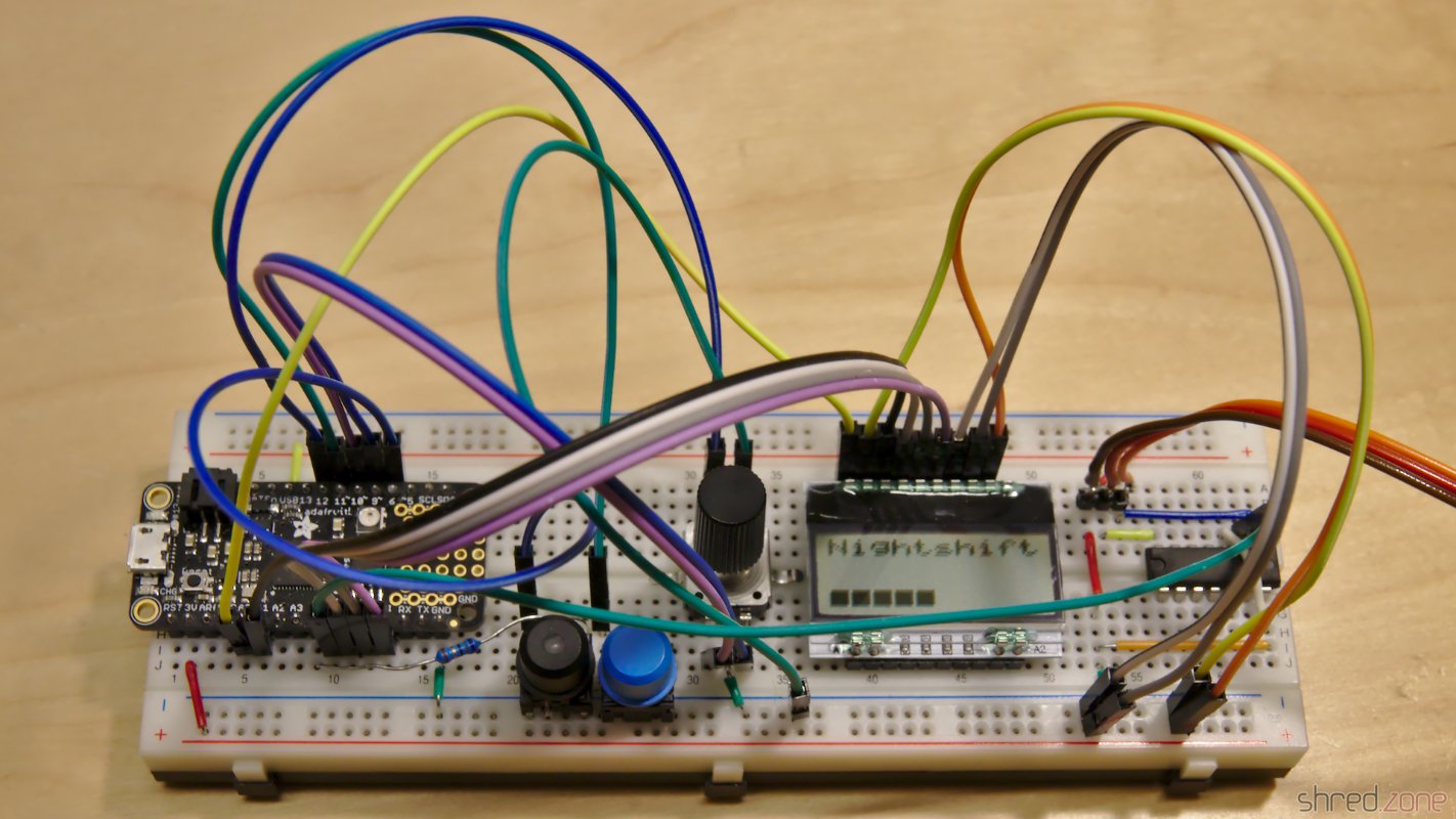
Now it's time to extend the hardware to its final stage. I'd like to have a LC display that shows the current settings. A button and a rotary encoder allows to browse through different menus and change the parameters. And finally, the strip shall be switched on and off by an illuminated power button.

Thanks to the bread board, the components were quickly added and connected to the Feather with some wires. Polling the buttons is a basic functionality of CircuitPython. It was also incredibly easy to poll the rotary encoder, because CircuitPython already comes with a library for that.

It took a lot more time to set up the LC display. CircuitPython supports SPI out of the box, but the SSD1803A controller of the display uses a weird protocol. Each command byte must be split up into two nibbles (4 bits), which are packed into bytes again, with the bit order reversed. The SPI library does not offer support for it, so I had to do all this bit mangling in Python, which turned out to become a rather ugly piece of code.

But then, finally, a minimal version of the firmware was working. I could turn the light on and off, select between two light effects, and I could also control the brightness.

However the Feather often took long breaks, where it did not react on key presses for multiple seconds. I guess the reason for that is Python's garbage collector, which stops the world while it is collecting unused objects and freeing some memory. This was actually a pretty annoying behavior that rendered the controller unusable.

After I added a third light effect, I also started to run into frequent out of memory errors. It seems that I have reached the limits of what is technically possible with CircuitPython on a Feather.

Was my approach too ambitious?

Luckily it wasn't. The Feather can also be programmed in C++, using the well known Arduino IDE. It comes with a lot of libraries that are ready to use. It's all very lightweight and is looking very promising. So why did I use Python in first place? Well, it is because I wrote my last lines of C++ code about 20 years ago. 😅

Porting the existing Python code to C++ was easier than I had expected. The SPI library now even supports reversed bit order, so it was much easier to address the LC display. On the down side, I had to test several libraries until I found a reliable one for the rotary encoder.

The C++ code consumes a fraction of the Python code's memory, so there is a lot left for extensions. The garbage collection breaks are also gone now, so the controller instantly responds to key presses. And I haven't even used the Feather's SPI flash memory yet. 😀

I have added some more light effects, and menus for adjusting brightness, saturation, and color temperature. Everything is working as expected now. It's time to finish the prototype phase and draw a circuit diagram.

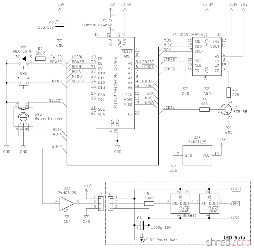
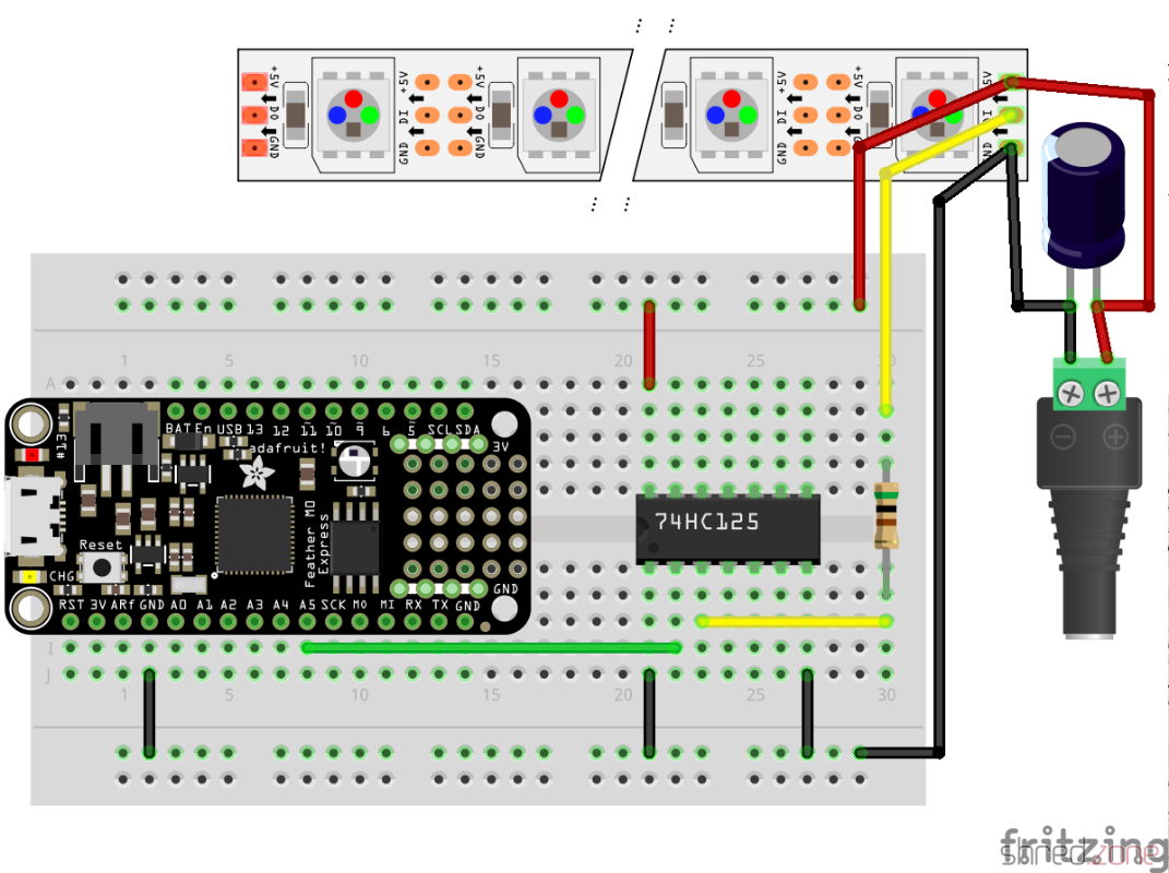
R2 is the series resistor for the power button LED. A green LED would need an 68 Ω resistor at 3.3 V. However the LED is directly connected to the Feather, so the current should not exceed 7 mA (maximum rating is 10 mA). A 500 Ω resistor limits the current to a safe value. If you need more current for a fancy power LED, you can use one of the three 74HCT125 drivers left, or add a transistor.

R3 is the series resistor for the LCD backlight. The manufacturer specifies a 27 Ω resistor when the backlight LEDs are connected in series and powered with 5 V. If you use a different backlight, change the resistor accordingly. The BC 548 transistor permits up to 100 mA in this configuration.

Remember: You must remove the jumper JP1 before connecting the Feather to an USB port, or your computer will be damaged.

In the next part, I'm going to grab my soldering iron and build a final version. It's high time. The many wires on the breadboard prototype are annoying when operating the rotary encoder. Also its pins are too short and are often disconnecting from the breadboard when I use it.

Premium Wall Bias Lighting, Part 1

A good way to relieve the strain from your eyes while working on a PC, is to illuminate the wall behind your monitor. Jason Fitzpatrick wrote an interesting article about what bias lighting is and why you should be using it.

Many light sources can be used as bias lighting. I have used an old bedside lamp for a while. But what about something more stylish? What about a LED strip on an aluminum profile?

In this project, I am going to make a Wall Bias Lighting myself, and write a controller software for it. The source code will be released on my GitHub profile eventually, so you will be able to customize it.

Proof of Concept

To make it a true premium lighting, I use a LED strip that consists of SK6812 RGBW LEDs. It can produce colors, but it also has separate white LEDs for a clean neutral white. Even better: Each LED can be addressed and the color changed individually. It would be possible to illuminate the wall behind the monitor in a bright white, while the visible parts of the strip are in a soft blue that won't dazzle the eyes.

AdaFruit sells these LED strips under their brand name NeoPixel, but there are also no-name strips on the market that are fully compatible and considerably cheaper. The strips are usually sold on reels of up to 5 meters length. They can be shortened to the desired size with scissors, and have an adhesive tape on the back so they can be glued to aluminum profiles.

This is the bill of material for the first proof-of-concept phase of the project:

  • An SK6812 RGBW LED strip with 60 LEDs per meter
  • An aluminum wall profile for LED strips
  • 1x AdaFruit Feather M0 Express
  • 1x Level converter (read below)
  • 1x 1000 µF/16 V capacitor, 1x 500 Ω resistor (read here why they are needed)
  • 1x 5 V power brick. Each LED is said to consume up to 60 mA (I couldn't find concrete figures), so you will need 18 W per strip meter if you want to set all four colors of all LEDs to maximum brightness.

The assembly was rather simple. First I cut the profile and the strip to the desired length and glued them together. Then I connected the strip to the power supply, and the strip's data line to the Feather via the level converter.

The next thing on the to-do list was a quick test drive, to check if some of the LEDs are defective. So I installed CircuitPython on the Feather, and wrote a tiny test program that just cycles through the colors red, green, blue, and white. With this pattern, even a single defective LED would immediately catch one's eye.

I turned on the power supply, aaaand... Nothing! 😲 All the LEDs stayed black.

I checked and double checked the wiring, but everything seemed to be correct. I tested my test program on the single NeoPixel that is mounted on the Feather, and it worked there.

Puzzled, I connected my scope to the data line of the LED strip. It immediately revealed the culprit.

The Feather runs on 3.3 V, and so the signal on the data line has an amplitude of 3.3 V.

The LED strip runs on 5 V though, and also expects a signal amplitude of 5 V. The logic converter between the Feather and the strip is supposed to convert the 3.3 V signal to 5 V. However, the BSS138 based bi-directional logic level converter from my spare part box turned out to be too slow for this purpose. The output level starts at 3 V and then ramps up to 4 V.

This is not sufficient for the SK6812, which needs a 5 V signal and a very precise timing with clean signal edges. Both was not given, so the LEDs stayed black.

I replaced the logic level converter by a standard 74HCT125 buffer IC, and tried again. The LED strip immediately came to life and cycled through the colors. The scope now shows a clean (well, more or less clean) 5 V signal.

My proof-of-concept is working. 🎉 This is what the circuit looks like:

While the LED strip is powered by the power brick, the Feather is going to be powered by USB as long as I am developing the software. Later I will also supply the Feather with LED power, so it runs stand-alone.

Never connect the Feather to an USB port while it is supplied by an external power source. It could damage your computer.

What next? I'm going to add a power button, so I can turn the light on and off. For controlling the brightness and light effects, I am also going to add a display, a rotary switch, and another button. Stay tuned…

Circuit Playground Halloween Ghost

Just in time for Halloween 🎃, I made a ghost decoration that uses an Adafruit Circuit Playground Express.

The ceramic ghost is from a home decoration shop. I have put a little piece of sandwich paper inside, so the LED light can be seen through the ghost's mouth and eyes.

The MicroPython source shows a candle light effect. For the flame, a mystic cyan color is used, so the ghost appears really spooky. 👻

If you copy .wav files to the Circuit Playground, a random sound effect is played from time to time. I found nice free sound effects on soundbible.com that surely give everyone the chills. The sound files should be converted to mono and 16 kHz sampling rate, so they fit into the tiny Playground Express memory. The sound effects can be muted using the switch on the Playground, if they should become too annoying. 😉

Continue reading...
CircuitPython and Fedora

The season of long winter nights is coming, so I got myself an AdaFruit Circuit Playground Express for some home decoration.

My plan is to program it using CircuitPython, a MicroPython derivate that is adapted to the AdaFruit hardware.

CircuitPython must be installed to the Circuit Playground first, which turned out to be difficult with Fedora Linux in a first attempt. The troublemaker was the ModemManager, which is still installed by default. It detects the serial port of the AdaFruit device, and then hogs this resource because, well, it might be a modem. 🙄

My older readers certainly still remember what a modem is. 😉 But to make a long story short, almost no one is using a serial modem nowadays, so the ModemManager does not serve any useful purpose. However, it cannot be removed, because other important packages still depend on it. The only way is to stop it permanently:

sudo systemctl stop ModemManager
sudo systemctl disable ModemManager

After that, I could finally install CircuitPython to the Circuit Playground. First I downloaded the matching uf2 file. After that, I connected the Playground via USB, and changed to the bootloader mode by pressing its reset button twice (like a double-click).

The Circuit Playground is now mounted as an USB drive called CPLAYBOOT. All there is to do now is to copy the uf2 file to this drive. The Playground automatically reboots after that. If everything went fine, it will come back as an USB drive called CIRCUITPY.

The next step is to install the AdaFruit libraries to that drive. I downloaded the latest library bundle that matched my CircuitPython version, and just unpacked it to the CIRCUITPY drive.

That's it... All there is to do now, is to open the code.py file in an editor and change the code. It is immediately executed when it is saved.

For a start, there are a lot of code examples for the Circuit Playground Express on the AdaFruit web site.