Dev.Microcontroller

LoRa Washing Machine

Sometimes you cannot choose your project, but the project chooses you. This one is about sending the status of a Home Connect clothes washer to MQTT using LoRa radio communication.

The project can be found at GitHub.

The Problem

It all started when my clothes washer broke down. I replaced it with a new one, one that is also IoT capable by using the Home Connect network. I liked the idea because the machine is located in a shared laundry room at the basement of the building. If I knew about the progress and the remaining time, I could go to the basement and swap the laundry right on time, not too soon and not too late.

However, my WLAN does not reach the basement, so I couldn't connect the washer to the Home Connect cloud. I tried PLC, but that made my DSL connection instable, so it wasn't a solution either. I pondered about buying an LTE router, but the data tariff would cause monthly costs that I wasn't really willing to pay.

Then I discovered LoRa, which is a radio communication technique that is specially designed for Long Range (hence its name) communication, with a range of up to several kilometers (on optimal conditions). It should be easy for LoRa to send data from the basement to my flat, and indeed, a first test was successful.

LoRa solves the problem of transporting the data. However, it comes with a price: The individual data packages are very small (about 50 bytes worst case), and in Europe there is also a 1% duty cycle restriction that needs to be respected. So it wasn't possible to just connect the washer to the Home Connect cloud using LoRa as some kind of WLAN repeater.

Instead of that, I would have to connect to the washer directly, read its state and compress the information to what I actually need, before sending it. The problem is now that the connection between the appliance and the Home Connect cloud is proprietary and encrypted.

I found the solution to that problem in a blog post "hacking your dishwasher" by Trammell Hudson. By smart reverse engineering, Trammell was able to find a way to directly connect to his home appliances, without having to go through the Home Connect cloud. This was the last part of the puzzle that I needed.

Concept
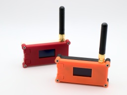
The LoRa32 sender and receiver in their case. With Trammell's work, I was able to connect to my washer and read its current state. Basically, the washer is sending key-value pairs via JSON, where the key seems to be a 16 bit integer, and the value is mostly also an integer, but could also be a boolean or a string. This information can be easily compressed into small LoRa packages, as I mostly need to transport numeric key-value pairs.

So there is a LoRa "sender" at the basement. It spawns a WLAN access point that the washer connects to. It then communicates with the washer, retrieves its state change events, compresses them, and sends them out via LoRa.

In my flat, a LoRa "receiver" uncompresses the information. From it, JSON bodies are generated and sent to my home automation's MQTT queue. The generated JSON bodies resemble those sent by Home Connect. A display that is connected to MQTT shows the current progress and the remaining time of the washer. I will also get a message on my phone when the washer is completed, or if an error has occured.

Implementation
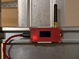
The LoRa32 sender in the basement. For the implementation, I bought two Heltec LoRa32 V2 modules. They are based on an ESP32, with a LoRa module and an OLED on board. With a few modifications to the source, any other Semtech SX1276 based LoRa module can be used. For a proper housing, I created a 3D printed minimal Heltec LoRa32 V2 case.

Thanks to Trammell's hcpy source code, it was surprisingly simple to write a C++ class for the ESP32 that opens a web socket connection to the washer and starts communicating with it.

As mentioned above, the washer is sending JSON messages that contain mostly integer based key-value pairs. To stuff as much information as possible into a single LoRa packet, I came up with a simple compression. The first byte is stating the type of information, followed by a 16-bit integer key, optionally follwed by the value. These are the possible types:

  • 0: Represents the constant 0 (so no value needs to be transported)
  • 1: Represents an unsigned 8-bit integer (so the value consumes 1 byte)
  • 2: Represents a negative unsigned 8-bit integer (the positive value is transported, and then negated on the receiver side)
  • 3,4: The same, but for 16-bit integers (the value consumes 2 bytes)
  • 5,6: The same, but for 32-bit integers (the value consumes 4 bytes)
  • 7: A boolean constant false (so no value needs to be transported)
  • 8: A boolean constant true (so no value needs to be transported)
  • 9: A string (followed by the null-terminated string as value)

These key-value pairs are collected until the LoRa package is full or the sender is flushed. A length byte is added that contains the total length of the pairs, so the receiver is able to unpack all of them again.

To secure the communication, a SHA256 based HMAC is generated. A random 16 bit package number is added as well, which is used by the receiver for acknowledgement. Finally, the package is encrypted using AES256.

The receiver side will unencrypt the package and generate an HMAC, using a shared secret. If the HMAC matches, an acknowledge package with the package number is sent back to the sender. After that, the payload is uncompressed and converted to JSON strings that are sent to MQTT.

It is important to know that the transport encryption is not state-of-the-art. There are several sacrifices that had to be made to keep the LoRa transport small and simple:

  • Only the first 4 bytes of the MAC are used, for space reasons.
  • The RSA256 encryption does not use a mode of operation, mainly because it would be hard to re-synchronize the LoRa connection if a package was lost. On the other hand, we are only sending the washer state. If someone would want to find out whether the washer is running or not, they could just check if a package has been sent within the past minute.
  • The transport is not secured against replay attacks. The receiver should provide a random nonce, which is then used by the sender for the next package. This is something that should definitely be addressed.

So the LoRa connection provides an acceptable encryption, and is also protected against lost packages, since the sender will reattempt to send the package if there was no acknowledgement from the receiver.

Configuration

My MQTT display is showing the current progress (80%) and the remaining time (0:40) of the washer. The trickiest part of the project is probably the configuration.

To directly connect to the Home Connect appliance, an encryption key and (depending on the protocol) an initialization vector is required. Both parts cannot be retrieved by the public Home Connect API, but you need to trick the API into thinking that you are connecting from the Home Connect app. This is where Trammell's hcpy project comes into play. It will let you log into your Home Connect account, and then extract a profile of your appliance and writes it into a config.json file. This file is required for setting up my project.

The config-converter.py in my project will take this config.json file and extract all the necessary parts from it. It will print the appliance's key and iv values for your sender/config.h. It will also create a new random shared secret for the LoRa encryption. And last but not least, it will create a receiver/mapping.cpp file, which is used to convert the integer keys and values to strings similar to the Home Connect API.

If you came this far, you made the hardest part. After that, the LoRa transceivers need to be configured. Unfortunately the parameters depend on the country where the sender is used, so there are no general default settings.

The following values are proposals and are only valid for countries of the EU. You are responsible to find the correct settings for your country. Failure to do so may result in legal problems, claims for damages, and even imprisonment.

  • LORA_BAND: This is the frequency used for LoRa transmissions. For EU countries this is usually 867E6.
  • LORA_POWER: The power of the LoRa sender, in dB. For EU countries this must be 14 or less.
  • LORA_PABOOST: true for EU countries.
  • LORA_SPREADING: The spreading factor. For EU countries, values between 7 and 12 are allowed. Higher values span longer distances, but also exhaust the permitted 1% duty cycle sooner. You should use the lowest possible value that gives a stable LoRa connection, and rather try to enhance reception by finding a better place for the LoRa devices or by using better antennas. The value should be 9 or less, as the duty cycle limit is likely to be exceeded with higher spreading factors.
  • LORA_BANDWIDTH: The bandwidth, must be 125E3 in EU countries.
  • LORA_SYNCWORD: A sync word. You can choose basically any values, or just use the default 0x12.

Make sure that the sender and the receiver are using the same settings, otherwise the transmission will fail.

The other settings are mainly about the WLAN access point for your appliance, the WLAN settings of your home network, and the credentials to access your MQTT server.

And that's it! Actually it was quite a fun project, and I learned a lot about ESP32 programming and LoRa networks. I also spent way too much time with it, but maybe it will pay off because I get the laundry done sooner now.

Thunderbolt and Lightning

 The Kaminari Lightning Detector Pyramid I recently found an article about the AS3935 Franklin Lightning Sensor. As I am already recording some weather data, it immediately raised my interest.

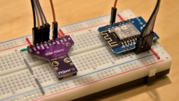
The sensor module can be found at many online shops selling products from China. It is not really cheap, but still affordable. I decided to use an ESP8266 as microcontroller, so I can read the sensor data by WLAN. The sensor is connected to the ESP via SPI. There was also some space left for a SK6812 RGBW LED indicating the sensor status.

The result of this project can be found at GitHub. It's called Kaminari (which is Japanese for lightning), and also comes with OpenSCAD files for a 3D printed, pyramid shaped case with illuminated tip. In this article I will explain a bit about how I developed the Kaminari firmware.

The first problem was the calibration. The sensor is roughly pre-calibrated, but must be fine-tuned to 500 kHz ±3.5% via the TUN_CAP register. For this purpose, the antenna frequency can be routed to the IRQ pin and then be measured by the ESP. I chose to prescale the frequency by a ratio of 128, giving an IRQ frequency of 3,906.25 Hz. For measurement, I've set an IRQ handler that is just counting up a variable on each interrupt. I then reset the counter, wait for 1000 ms, then read the counter, and get the IRQ frequency in Hz units. It's not 100% accurate, but good enough for this purpose.

The TUN_CAP register offers 16 calibration steps. Just incrementing it until the frequency matches, would take up to 16 seconds. Instead I used an algorithm called successive approximation to find the correct calibration value in only 4 iterations, taking a quarter of the time.

 The AS3935 connected to an ESP8266 To my disappointment, it turned out that the manufacturer of my module (CJMCU) has used nonstandard components, so my module could only reach a maximum frequency of about 491 kHz. I first suspected that the ESP might be too slow for this kind of measurement, but a scope connected to the IRQ pin confirmed the frequency. Well, it is still within the required tolerance, but it gives a suboptimal tuning result and renders the TUN_CAP register useless.

The next problem is finding a good noise floor level. This is some kind of background radio noise filter. If the level is too low, the sensor cannot operate properly because of interfering background noise. If it is set too high, the lightning detection quality declines.

The noise floor level cannot be calibrated just once at the start. Radio noise sources come and go, may it by turning on an electronic device or just by a change in the weather. I did some experiments, and the most promising solution is a kind of tug-of-war. When the AS3935 detects too much noise, it triggers an interrupt, and the noise floor level is raised to the next higher step. If the last level change was 10 minutes ago, the ESP attempts to reduce the level by one step.

In order to reduce the number of level changes, I have added a counter. Each noise interrupt increments the counter, and every 10 minutes the counter is decremented. The level is raised when the counter reaches 2, and lowered when the counter reaches -2.

Sometimes I noticed a "noise level runaway", where the AS3935 triggers a lot of noise interrupts in a very short time, raising the noise floor level to its maximum value immediately. To stop that behavior, further noise interrupts are being ignored for one minute after a noise interrupt has been processed.

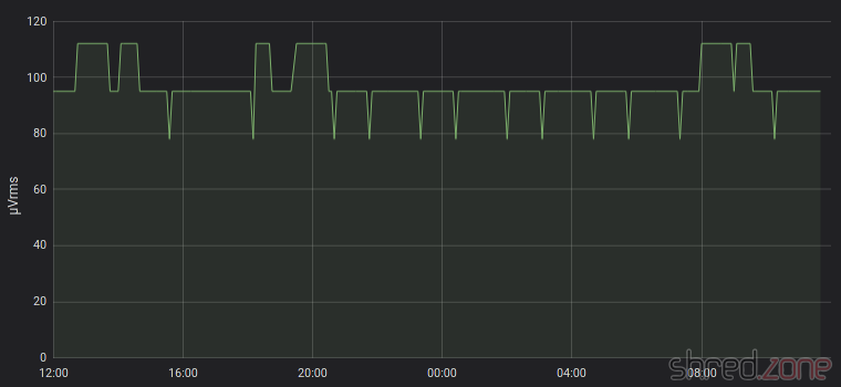
Now the noise floor level has settled to an average of 95 µVrms here. In the graph, one can see that the level is raised at some time, but then reduced again after a while. One can also see the frequent attempts to lower the level a bit further, immediately followed by a raise back to the average level. It seems that the AS3935 and the ESP have negotiated a good compromise. 😉

The AS3935 seems to be set up in an optimal way now, but I still get some false lightning events from time to time. There are a few registers left to experiment with, namely WDTH (watchdog threshold), SREJ (spike rejection) and MIN_NUM_LIGH (minimum number of lightning). I have raised the watchdog threshold to 2, and did not have a false lightning event since then.

Now I have to wait for some real lightnings… 😄

Premium Wall Bias Lighting, Part 3

I haven't forgotten about you. Some private stuff kept me from completing this project for a while. To make it up, I have added OpenSCAD files for a 3D printed case.

The controller was a little tricky to complete, mostly because of the very different component heights. I decided to use two circuit boards that are stacked onto each other by headers.

On the upper board, there are only the two buttons and the LCD, as well as the transistor and resistor for the LCD backlight. As I only used one-layer TriPad strip boards, I had to use this one upside down for the male headers to point downward. This rather unconventional use made it a little tricky to solder the buttons and LCD headers on the actual bottom side of the board.

The soldered controller boards. The lower board contains all the other components, as well as the wiring. The rotary encoder also made it to the lower board, because it is much taller than the other buttons. This way, the top of the button caps are almost level and nice to look at.

The result is surprisingly compact for a DIY solution. The button caps and the LCD are just perfectly positioned for a case.

With plastic feet attached, you can use the controller as it is. You can also get a plastic case with transparent top, drill three holes in it for the button caps, and mount the sandwich with spacers. But if you have the chance, you should definitely go for a 3D printed case.

I have set up a project at GitHub. It contains the circuit diagram, the bill of materials, the firmware source code, and OpenSCAD files for a printed case. There is no firmware binary yet, as you need to adapt the source code to the length of your LED strip anyway.

You will find the OpenSCAD files for the case in the GitHub project. There are bonus OpenSCAD files in the project, for printing a customized case. Due to the absence of properly layouted PCBs, I am aware that each controller is going to look differently when finished. In the parameter.scad file, you can change all kind of parameters, so you should be able to make your individual case in, well, almost any case (silly pun intended). 😄

The SPI flash memory of the Feather M0 Express is not used yet. In a future release, I may add a settings menu for the LED strip size. The controller is also forgetting all its settings when disconnected from the power. This needs to be addressed in a future release as well.

But after all, this is a start for your own DIY wall bias lighting. Feel free to send pull requests for enhancements!

Again, remember that you must remove the jumper before connecting the Feather to an USB port, otherwise your computer will be damaged.

Premium Wall Bias Lighting, Part 2

The completed prototype on a breadboard In the first part, I have assembled a working proof-of-concept for my premium wall bias lighting. Thanks to CircuitPython, it just took a couple of minutes to program a light effect once the hardware was working.

Now it's time to extend the hardware to its final stage. I'd like to have a LC display that shows the current settings. A button and a rotary encoder allows to browse through different menus and change the parameters. And finally, the strip shall be switched on and off by an illuminated power button.

Thanks to the bread board, the components were quickly added and connected to the Feather with some wires. Polling the buttons is a basic functionality of CircuitPython. It was also incredibly easy to poll the rotary encoder, because CircuitPython already comes with a library for that.

It took a lot more time to set up the LC display. CircuitPython supports SPI out of the box, but the SSD1803A controller of the display uses a weird protocol. Each command byte must be split up into two nibbles (4 bits), which are packed into bytes again, with the bit order reversed. The SPI library does not offer support for it, so I had to do all this bit mangling in Python, which turned out to become a rather ugly piece of code.

But then, finally, a minimal version of the firmware was working. I could turn the light on and off, select between two light effects, and I could also control the brightness.

However the Feather often took long breaks, where it did not react on key presses for multiple seconds. I guess the reason for that is Python's garbage collector, which stops the world while it is collecting unused objects and freeing some memory. This was actually a pretty annoying behavior that rendered the controller unusable.

After I added a third light effect, I also started to run into frequent out of memory errors. It seems that I have reached the limits of what is technically possible with CircuitPython on a Feather.

Was my approach too ambitious?

Luckily it wasn't. The Feather can also be programmed in C++, using the well known Arduino IDE. It comes with a lot of libraries that are ready to use. It's all very lightweight and is looking very promising. So why did I use Python in first place? Well, it is because I wrote my last lines of C++ code about 20 years ago. 😅

Porting the existing Python code to C++ was easier than I had expected. The SPI library now even supports reversed bit order, so it was much easier to address the LC display. On the down side, I had to test several libraries until I found a reliable one for the rotary encoder.

The C++ code consumes a fraction of the Python code's memory, so there is a lot left for extensions. The garbage collection breaks are also gone now, so the controller instantly responds to key presses. And I haven't even used the Feather's SPI flash memory yet. 😀

I have added some more light effects, and menus for adjusting brightness, saturation, and color temperature. Everything is working as expected now. It's time to finish the prototype phase and draw a circuit diagram.

R2 is the series resistor for the power button LED. A green LED would need an 68 Ω resistor at 3.3 V. However the LED is directly connected to the Feather, so the current should not exceed 7 mA (maximum rating is 10 mA). A 500 Ω resistor limits the current to a safe value. If you need more current for a fancy power LED, you can use one of the three 74HCT125 drivers left, or add a transistor.

R3 is the series resistor for the LCD backlight. The manufacturer specifies a 27 Ω resistor when the backlight LEDs are connected in series and powered with 5 V. If you use a different backlight, change the resistor accordingly. The BC 548 transistor permits up to 100 mA in this configuration.

Remember: You must remove the jumper JP1 before connecting the Feather to an USB port, or your computer will be damaged.

In the next part, I'm going to grab my soldering iron and build a final version. It's high time. The many wires on the breadboard prototype are annoying when operating the rotary encoder. Also its pins are too short and are often disconnecting from the breadboard when I use it.

Premium Wall Bias Lighting, Part 1

A good way to relieve the strain from your eyes while working on a PC, is to illuminate the wall behind your monitor. Jason Fitzpatrick wrote an interesting article about what bias lighting is and why you should be using it.

Many light sources can be used as bias lighting. I have used an old bedside lamp for a while. But what about something more stylish? What about a LED strip on an aluminum profile?

In this project, I am going to make a Wall Bias Lighting myself, and write a controller software for it. The source code will be released on my GitHub profile eventually, so you will be able to customize it.

Proof of Concept

To make it a true premium lighting, I use a LED strip that consists of SK6812 RGBW LEDs. It can produce colors, but it also has separate white LEDs for a clean neutral white. Even better: Each LED can be addressed and the color changed individually. It would be possible to illuminate the wall behind the monitor in a bright white, while the visible parts of the strip are in a soft blue that won't dazzle the eyes.

AdaFruit sells these LED strips under their brand name NeoPixel, but there are also no-name strips on the market that are fully compatible and considerably cheaper. The strips are usually sold on reels of up to 5 meters length. They can be shortened to the desired size with scissors, and have an adhesive tape on the back so they can be glued to aluminum profiles.

This is the bill of material for the first proof-of-concept phase of the project:

  • An SK6812 RGBW LED strip with 60 LEDs per meter
  • An aluminum wall profile for LED strips
  • 1x AdaFruit Feather M0 Express
  • 1x Level converter (read below)
  • 1x 1000 µF/16 V capacitor, 1x 500 Ω resistor (read here why they are needed)
  • 1x 5 V power brick. Each LED is said to consume up to 60 mA (I couldn't find concrete figures), so you will need 18 W per strip meter if you want to set all four colors of all LEDs to maximum brightness.

The assembly was rather simple. First I cut the profile and the strip to the desired length and glued them together. Then I connected the strip to the power supply, and the strip's data line to the Feather via the level converter.

The next thing on the to-do list was a quick test drive, to check if some of the LEDs are defective. So I installed CircuitPython on the Feather, and wrote a tiny test program that just cycles through the colors red, green, blue, and white. With this pattern, even a single defective LED would immediately catch one's eye.

I turned on the power supply, aaaand... Nothing! 😲 All the LEDs stayed black.

I checked and double checked the wiring, but everything seemed to be correct. I tested my test program on the single NeoPixel that is mounted on the Feather, and it worked there.

Puzzled, I connected my scope to the data line of the LED strip. It immediately revealed the culprit.

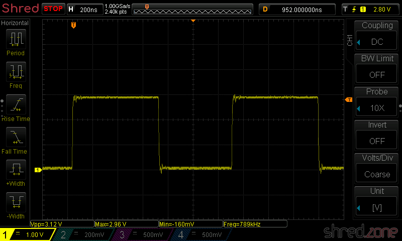
The Feather runs on 3.3 V, and so the signal on the data line has an amplitude of 3.3 V.

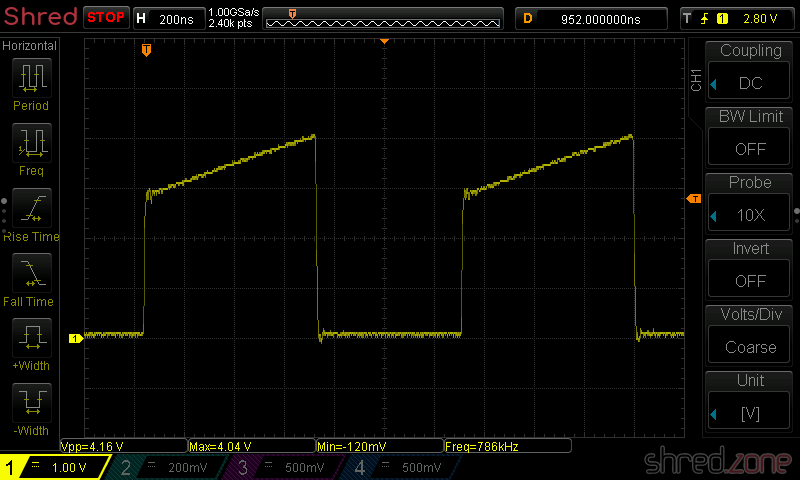
The LED strip runs on 5 V though, and also expects a signal amplitude of 5 V. The logic converter between the Feather and the strip is supposed to convert the 3.3 V signal to 5 V. However, the BSS138 based bi-directional logic level converter from my spare part box turned out to be too slow for this purpose. The output level starts at 3 V and then ramps up to 4 V.

This is not sufficient for the SK6812, which needs a 5 V signal and a very precise timing with clean signal edges. Both was not given, so the LEDs stayed black.

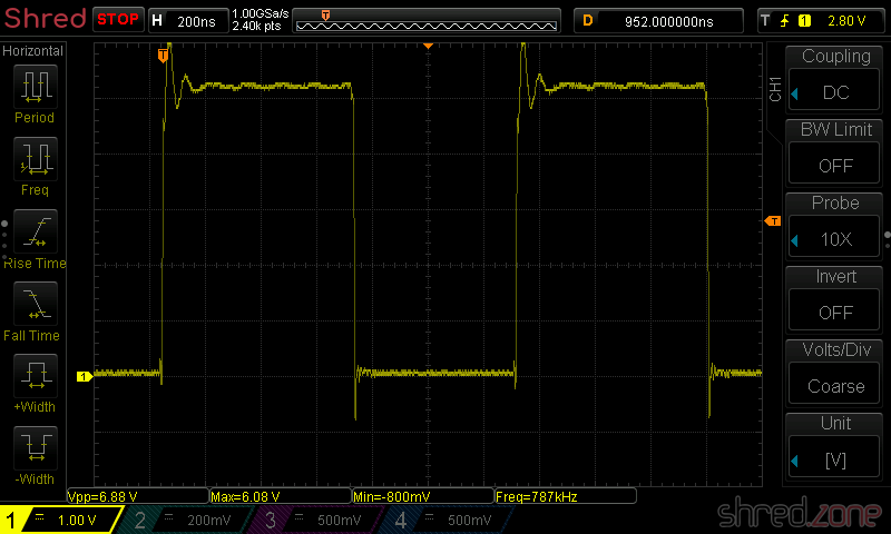
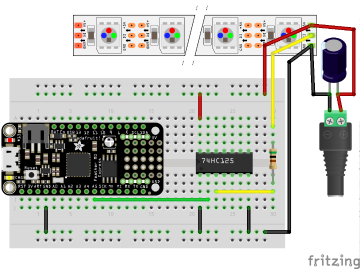
I replaced the logic level converter by a standard 74HCT125 buffer IC, and tried again. The LED strip immediately came to life and cycled through the colors. The scope now shows a clean (well, more or less clean) 5 V signal.

My proof-of-concept is working. 🎉 This is what the circuit looks like:

While the LED strip is powered by the power brick, the Feather is going to be powered by USB as long as I am developing the software. Later I will also supply the Feather with LED power, so it runs stand-alone.

Never connect the Feather to an USB port while it is supplied by an external power source. It could damage your computer.

What next? I'm going to add a power button, so I can turn the light on and off. For controlling the brightness and light effects, I am also going to add a display, a rotary switch, and another button. Stay tuned…