#ZX Spectrum

An Arabic Toast Rack

The Sinclair ZX Spectrum+ 128K "Toast Rack" This time, I have a true curiosity for you. 🙂

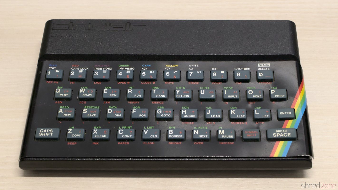
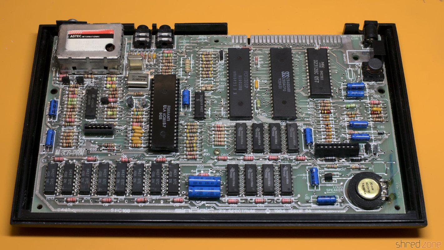
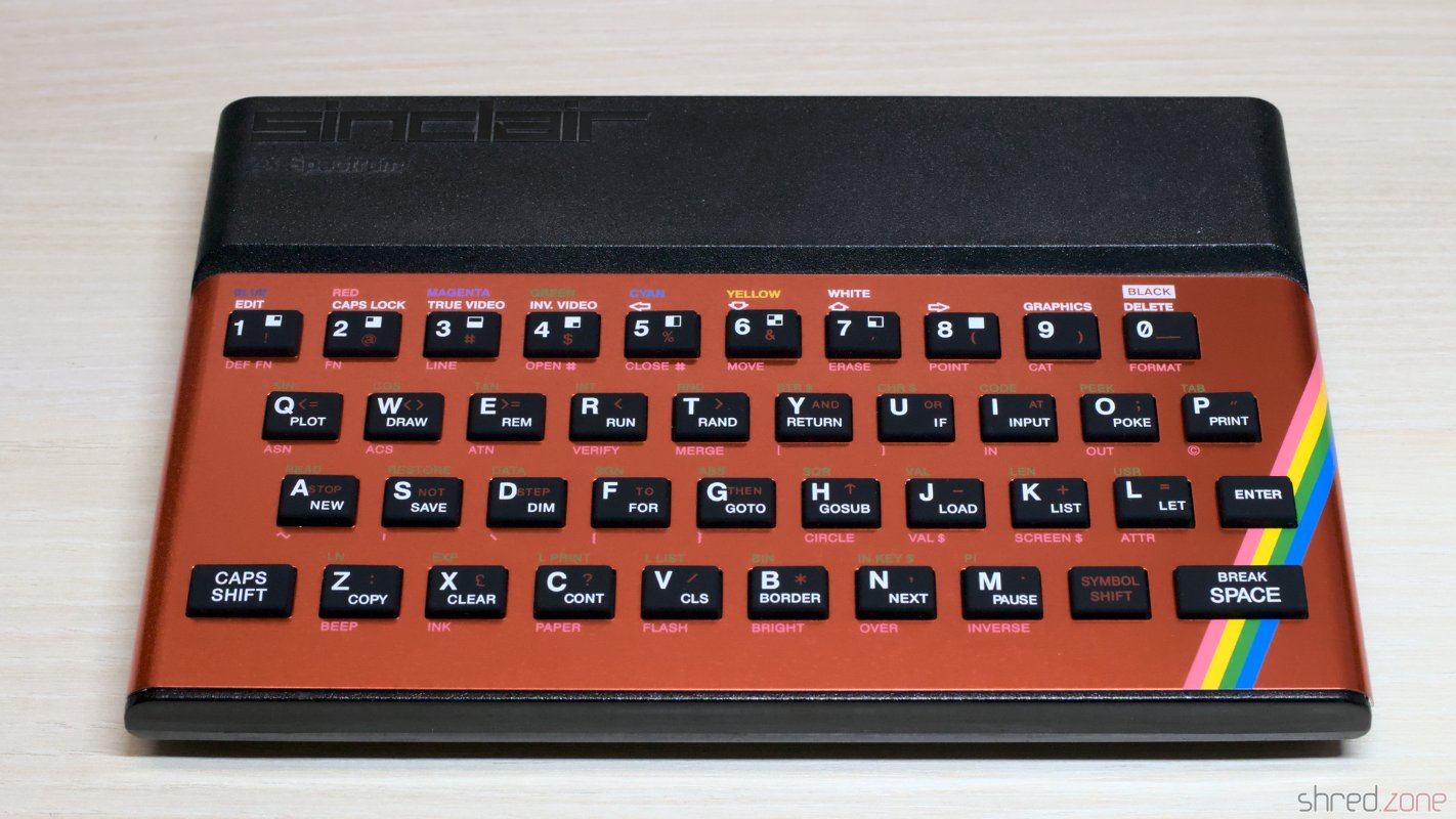
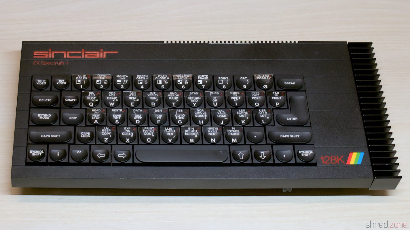
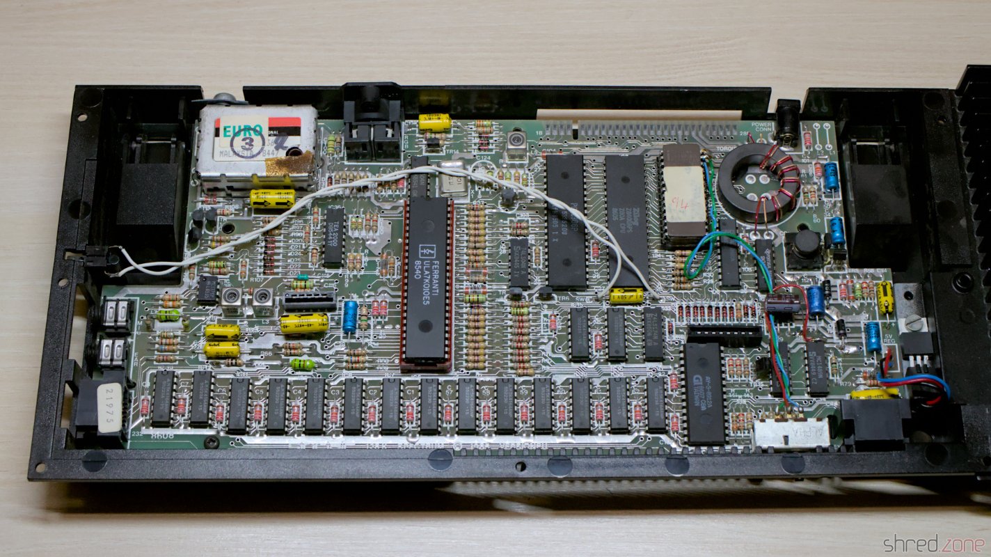
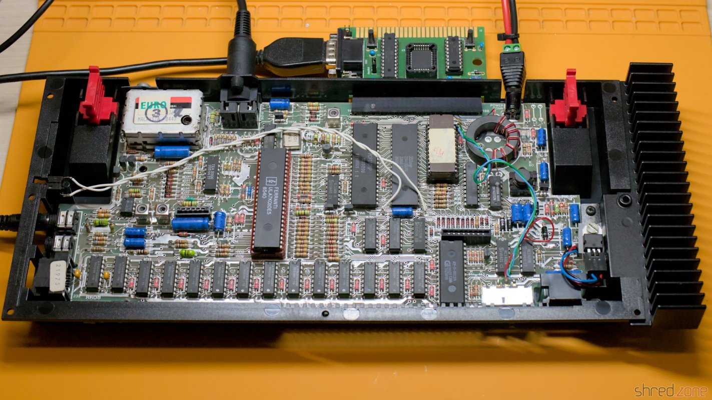
It's a ZX Spectrum 128K. It was designed by Sinclair and their Spanish distributor Investrónica, and was a major upgrade of the ZX Spectrum 48K. At that time, the 48K model was rather outdated with its limited RAM and the simple sound beeper, and Sinclair had nothing in its hand to compete with the Commodore 64 which was gaining ground in more and more households.

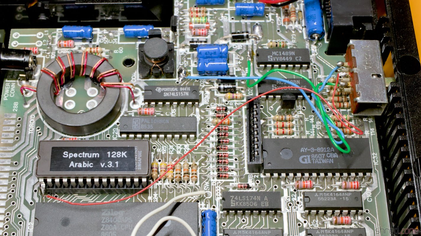
The 128K model has 128K of RAM (which also allowed double buffering), an AY-3-8912 sound chip, an RGB monitor port, a serial port and an optional external numerical keypad. Hardware sprites are still missing though. On software side, it provides a heavily improved BASIC.

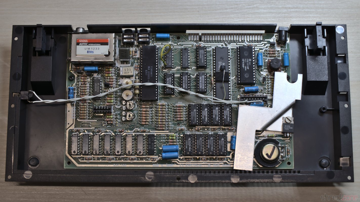
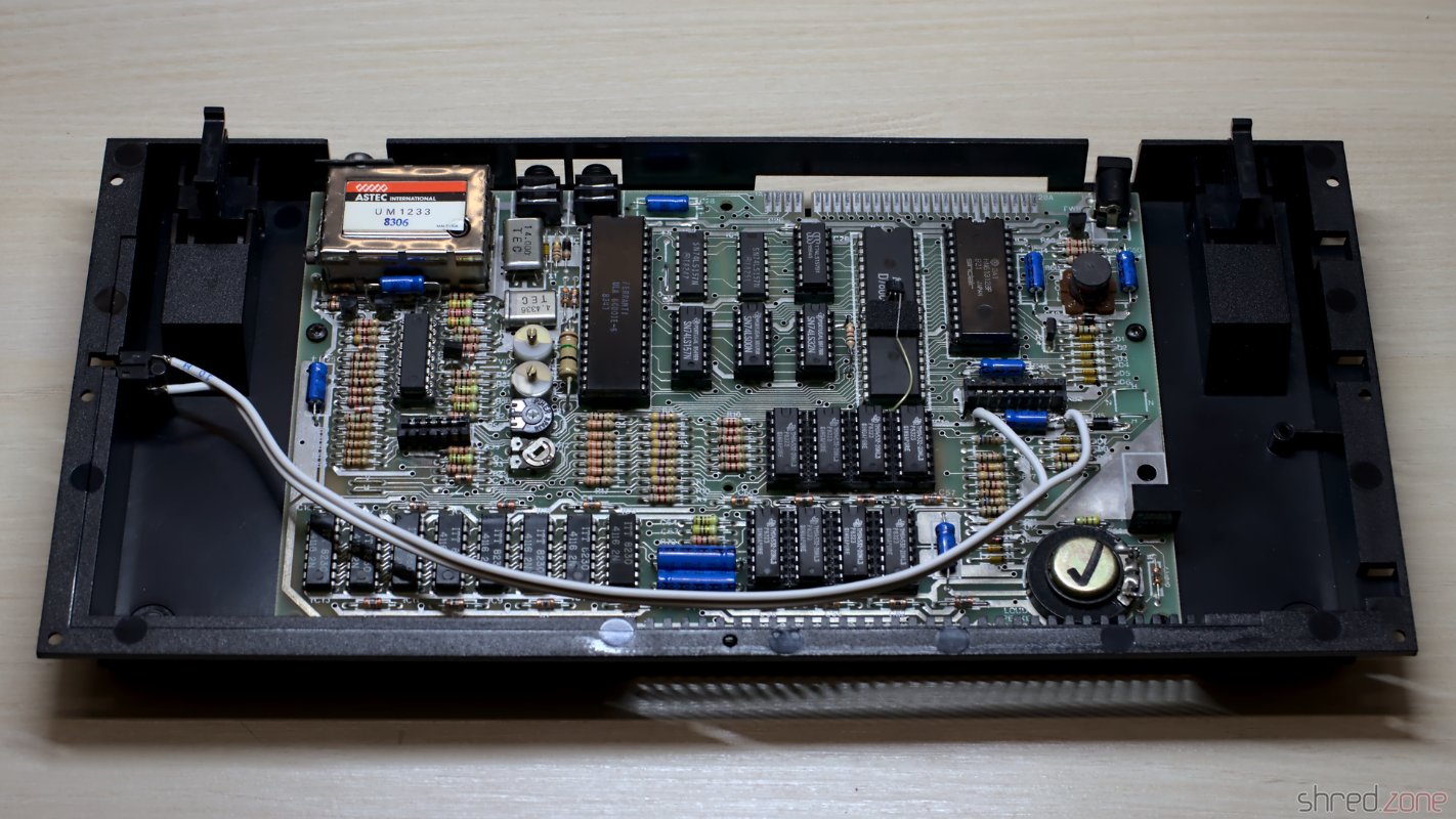
The shape of the prominent heat sink on the right side of the case gave the machine its nickname: "Toast Rack".

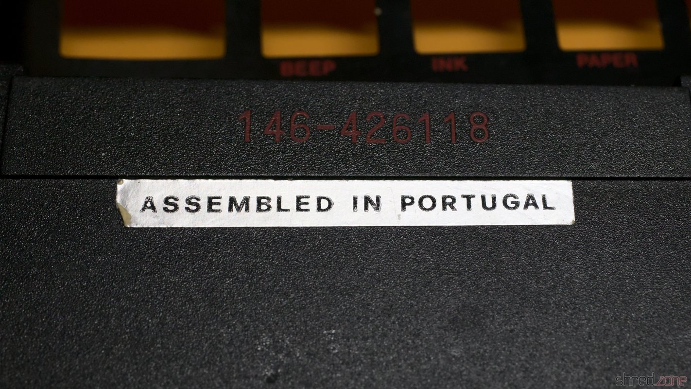
The model was first sold in Spain, as Sinclair UK still had a large number of unsold 48K models. In the end it could not save Sinclair from bankruptcy, but the 128K model was certainly very attractive for the new owner Amstrad. Today, the Toast Rack is a sought-after item for any serious Sinclair collector.

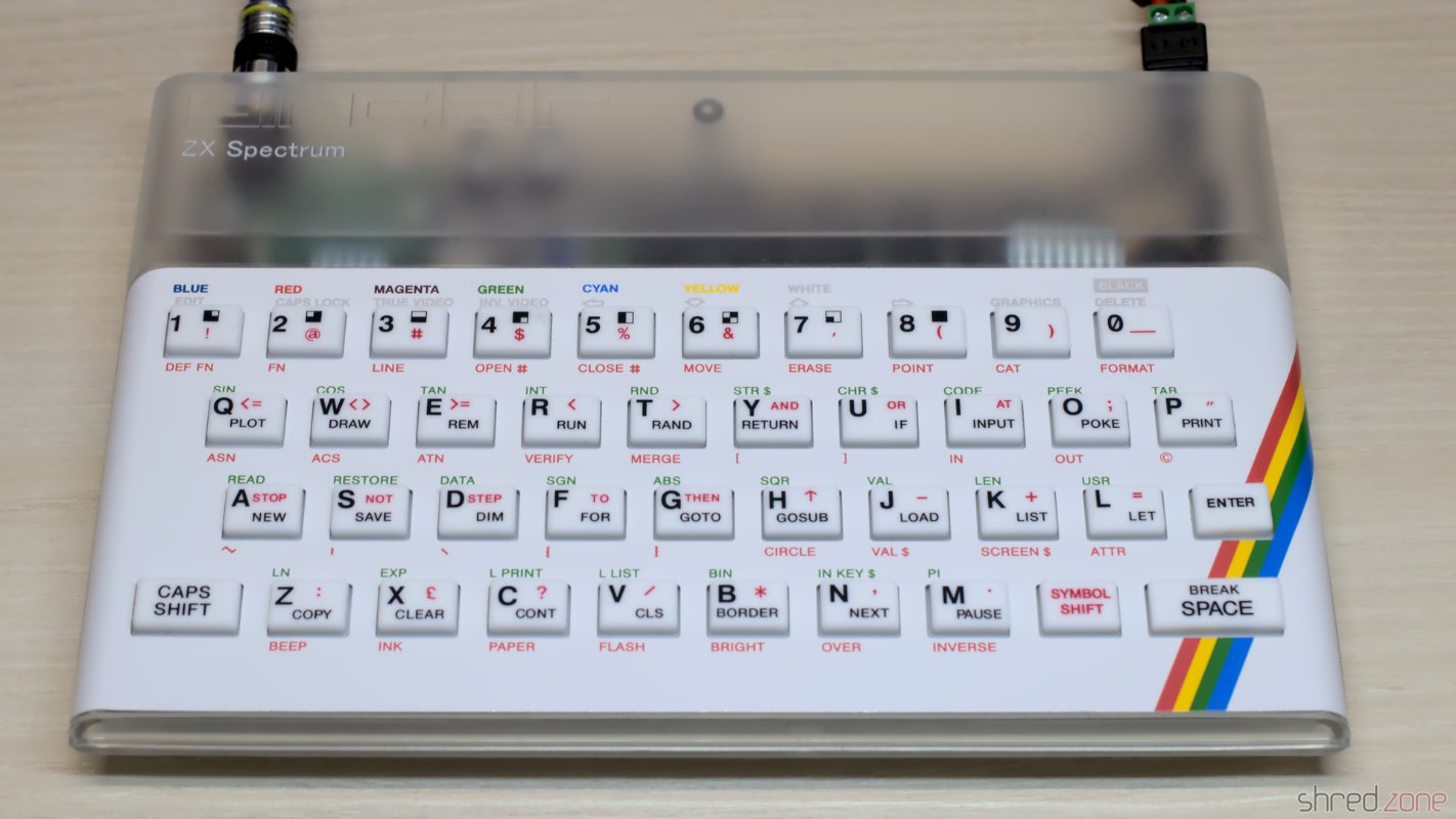
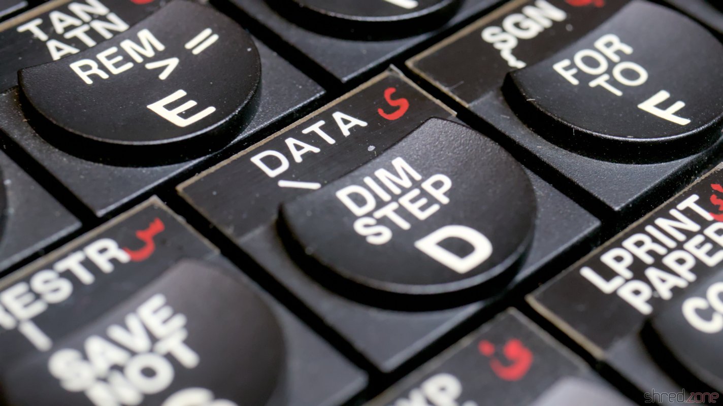
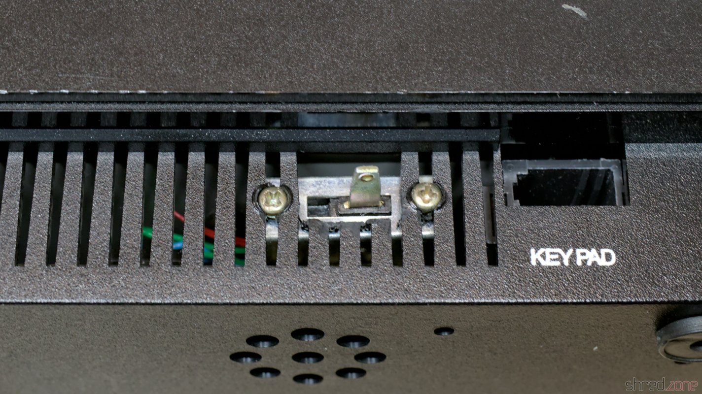
What makes this special model so curious is that it is an Arabic modification. 😀 There are stickers with Arabic letters on the keyboard, and at the front side there is a switch to select between the original 128K ROM and an Arabic version of the 48K ROM.

The stickers with Arabic letters on the keyboard. The front side with the switch, and a hand-written inscript "A gift of the Alumni Association".

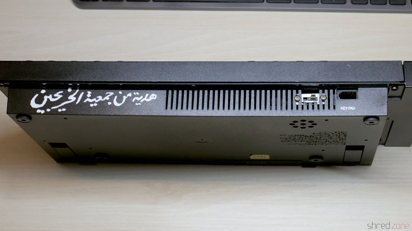
My first thought was that this was an elaborate DIY modification. But then I found a thread in a Sinclair forum. It says that Matsico, a Sinclair/Amstrad agency in Egypt, has produced these models. I could not find more information about it though, so I don't know if they were actually sold, or just made as a proof-of-concept or promotional gift.

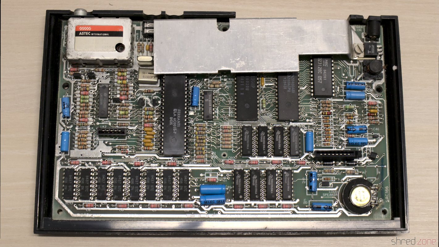
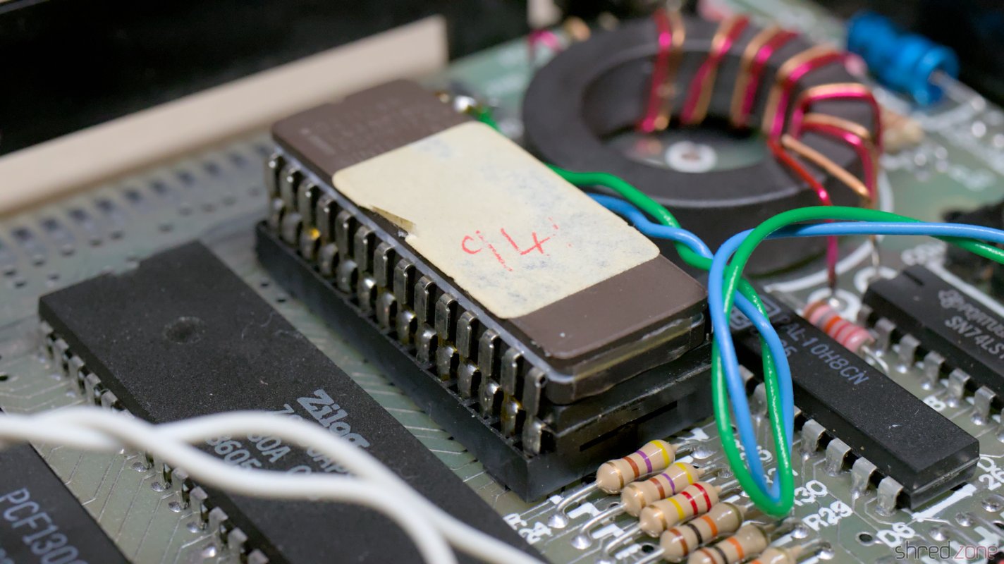
What they all have in common, is the switch at the front, and an EPROM soldered on top of the ROM. The only known exception I found in a video by ByteDelight about a ZX Spectrum +3, where the ROM could be selected via a separate boot menu.

Inside is an Issue 6U board. The EPROM with the Arabic version is soldered on top of the original ROM, presumably for license reasons.

Restoration

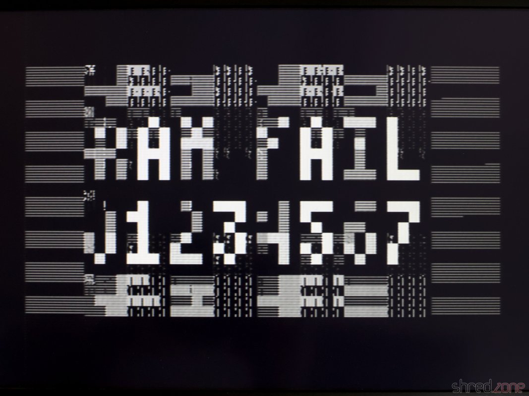
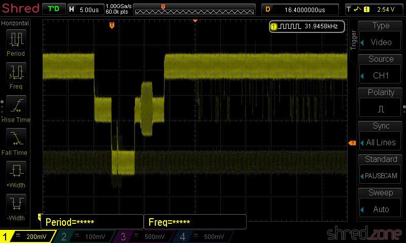
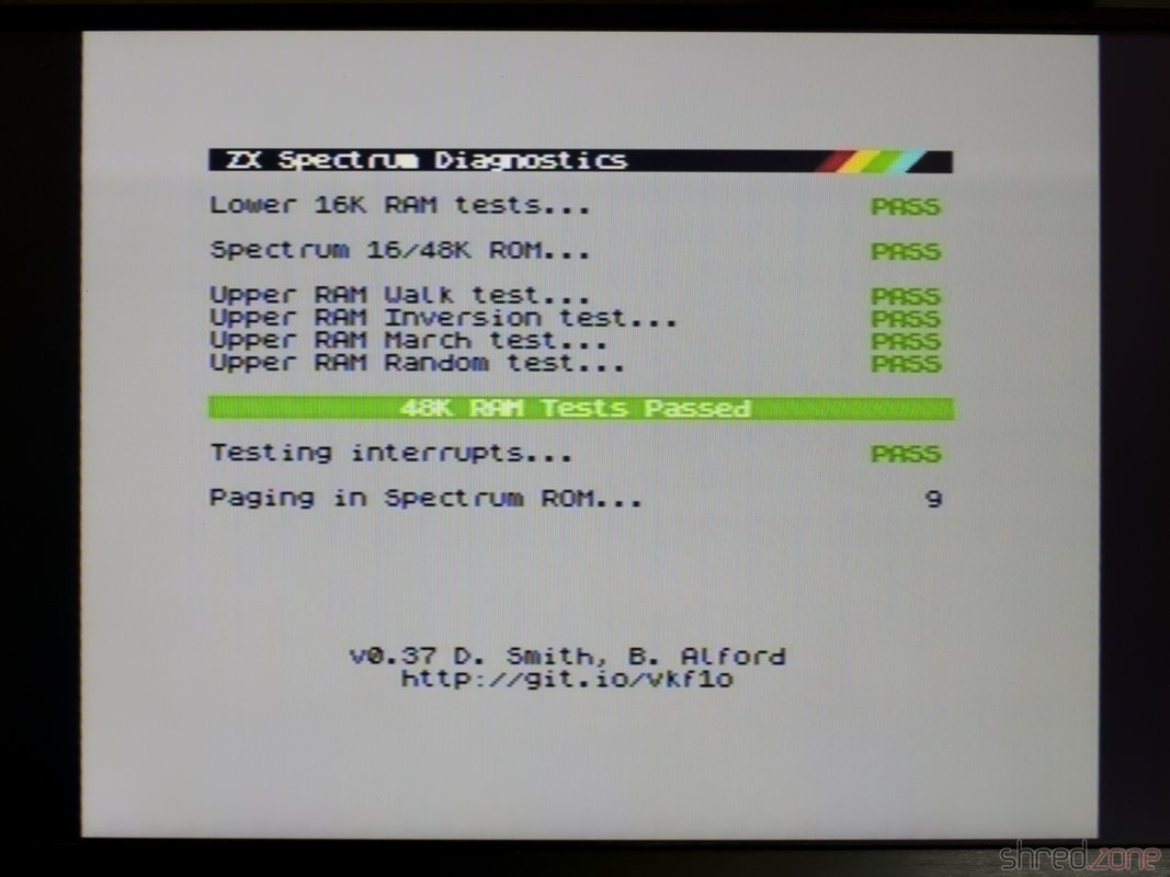
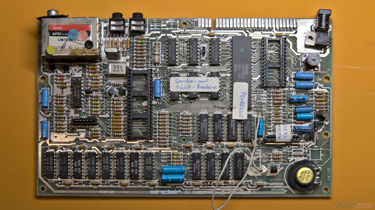
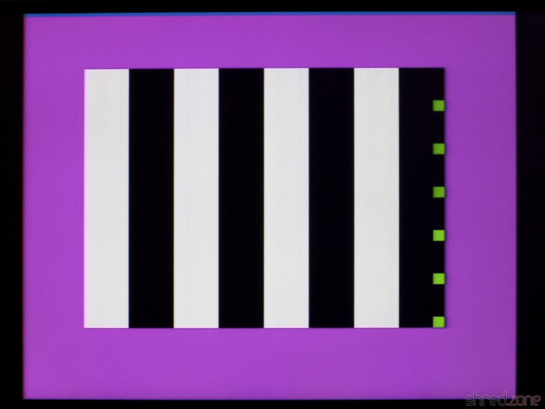
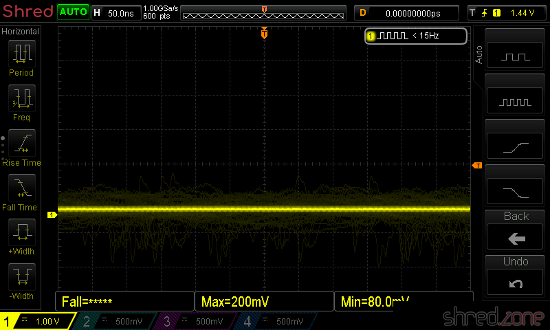
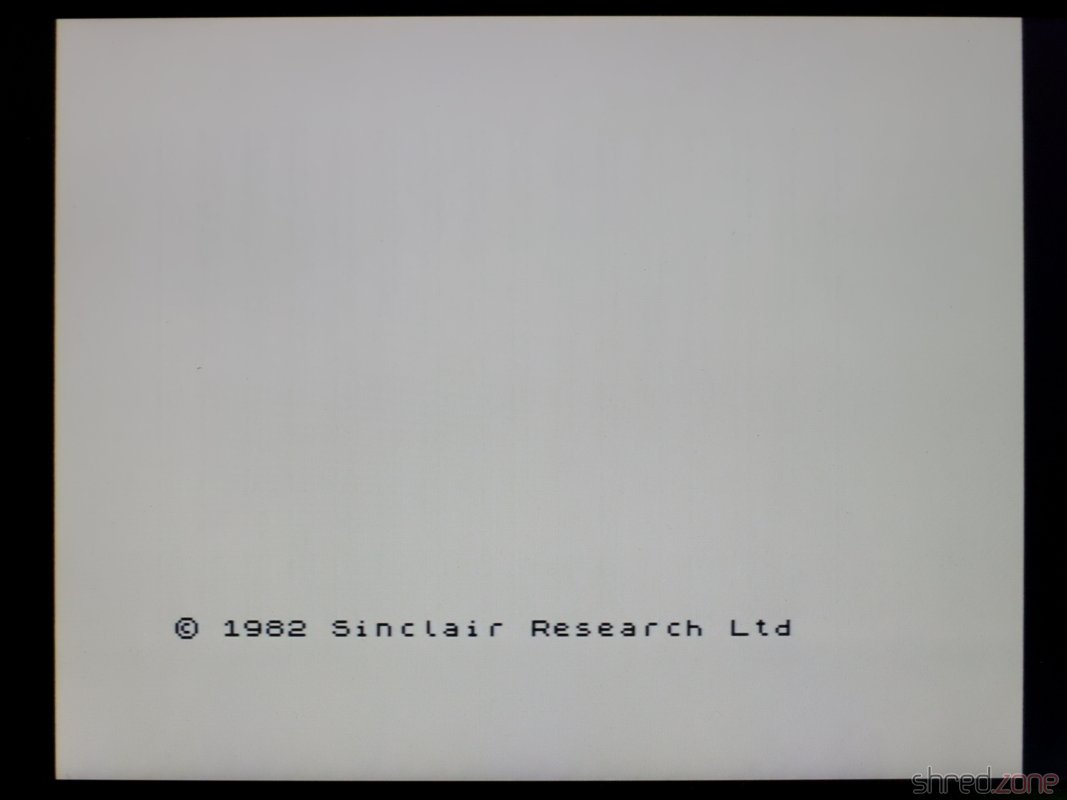
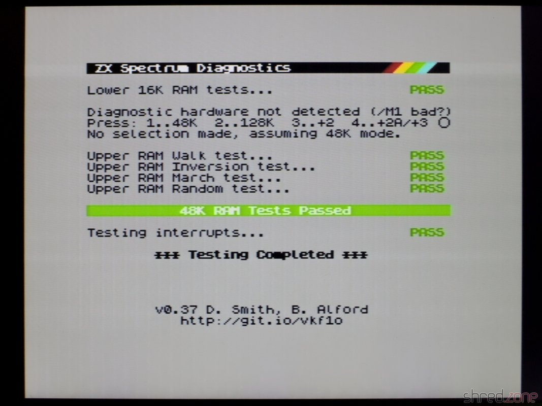
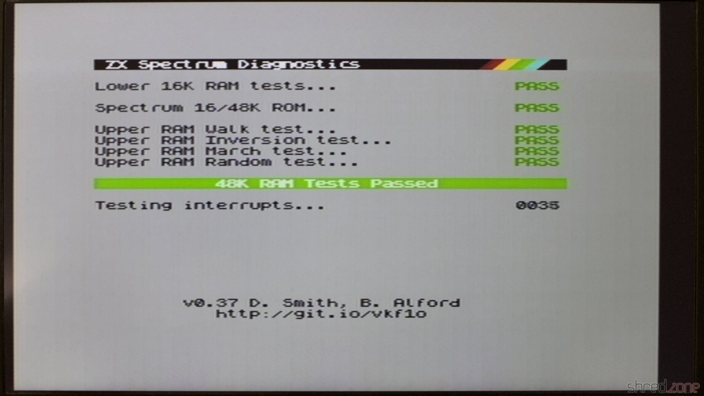
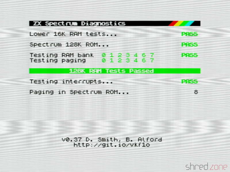
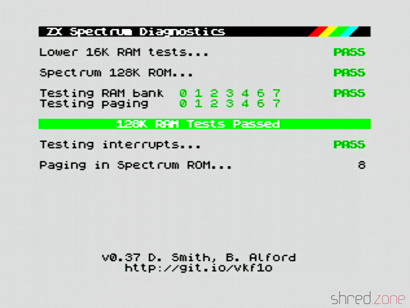
A first diagnostics run showed that the board was working fine. The only issues were massive picture interferences, and an almost inaudible sound from the AY chip.

Both issues are known problems with that model. A blog article by Adam's Vintage Computer Restorations addresses them.

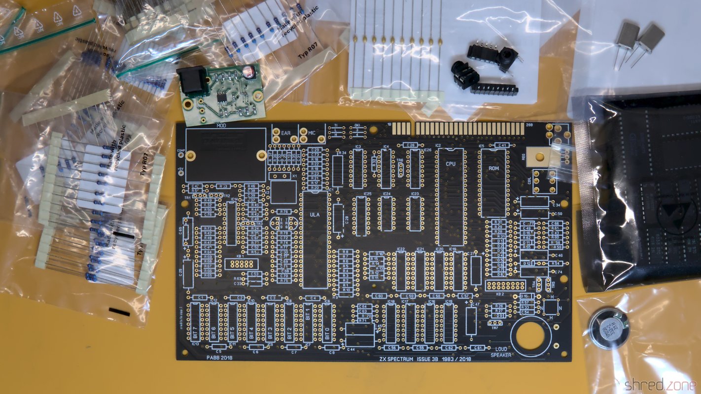
First of all, I replaced all electrolytic capacitors with premium ones. I'm doing that with all retro machines, irregarding their age and rareness. However I try my best to maintain the "retro optics", for example by using axial caps in that classic blue color.

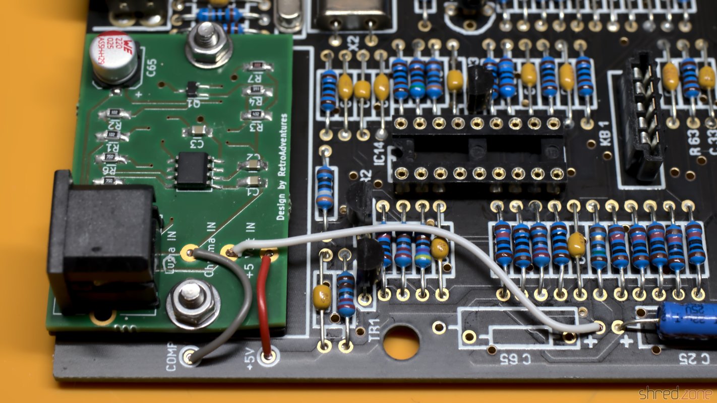
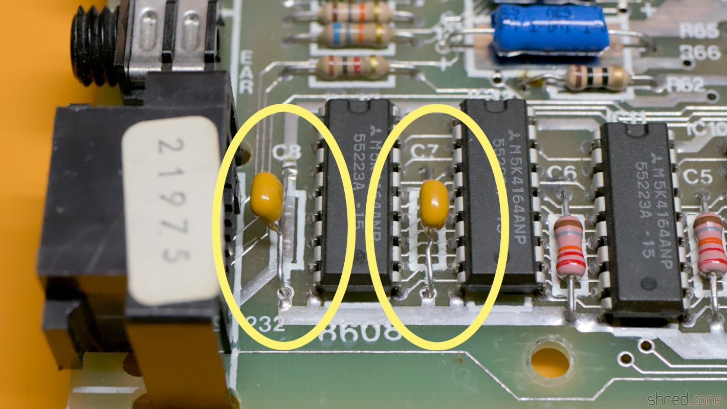
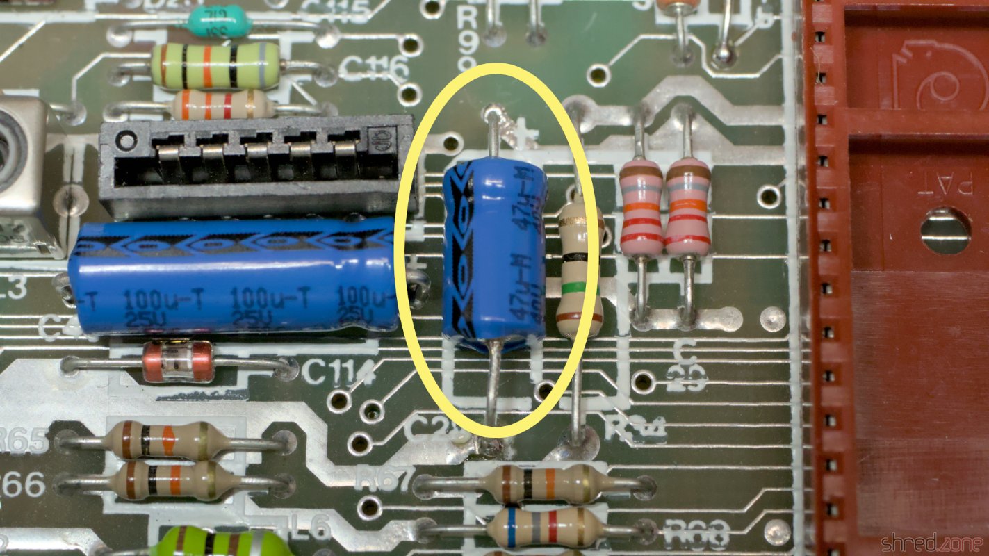
To enhance the image quality, I used a 47µF electrolytic cap for C28 (original was 22µF), and replaced C7 and C8 with 1µF MLCCs. I could also rewire C126 as mentioned in the blog article, to enhance image quality even further, but I decided to postpone that.

C7 and C8 replaced with 1µF MLCCs. Unfortunately I could not source axial ones. C28 replaced with 47µF.

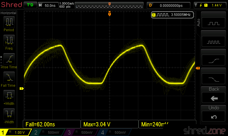
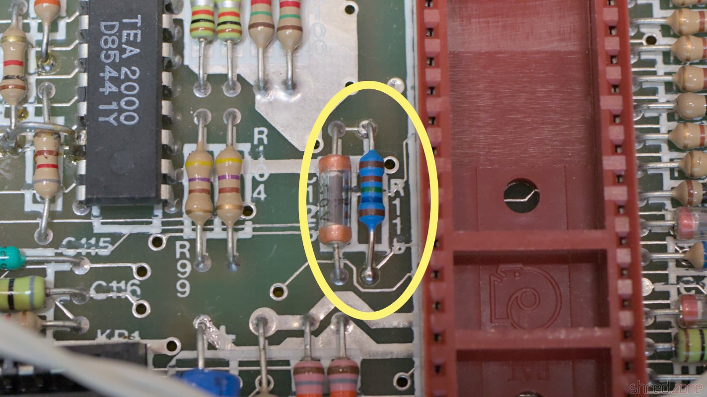
To raise the volume of the AY sound chip (so it has a similar level as the beeper), I replaced R115 with a 1.65kΩ resistor.

R115 replaced with 1.65kΩ.

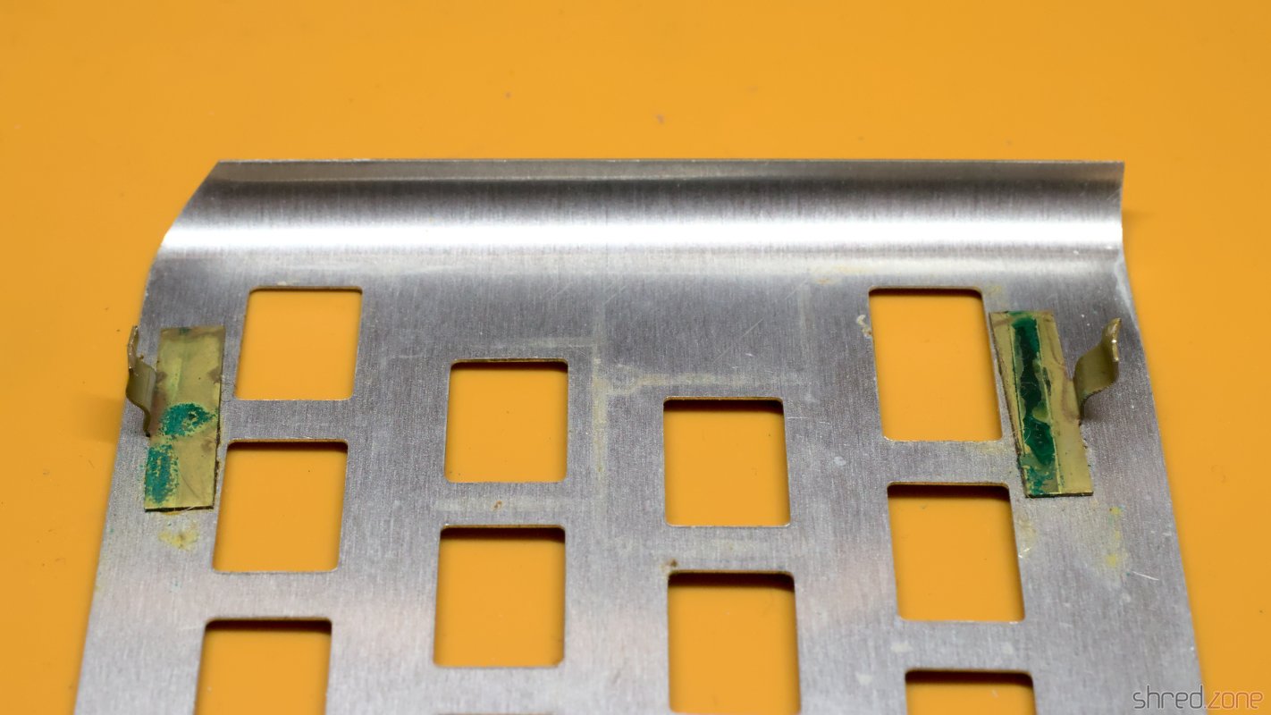
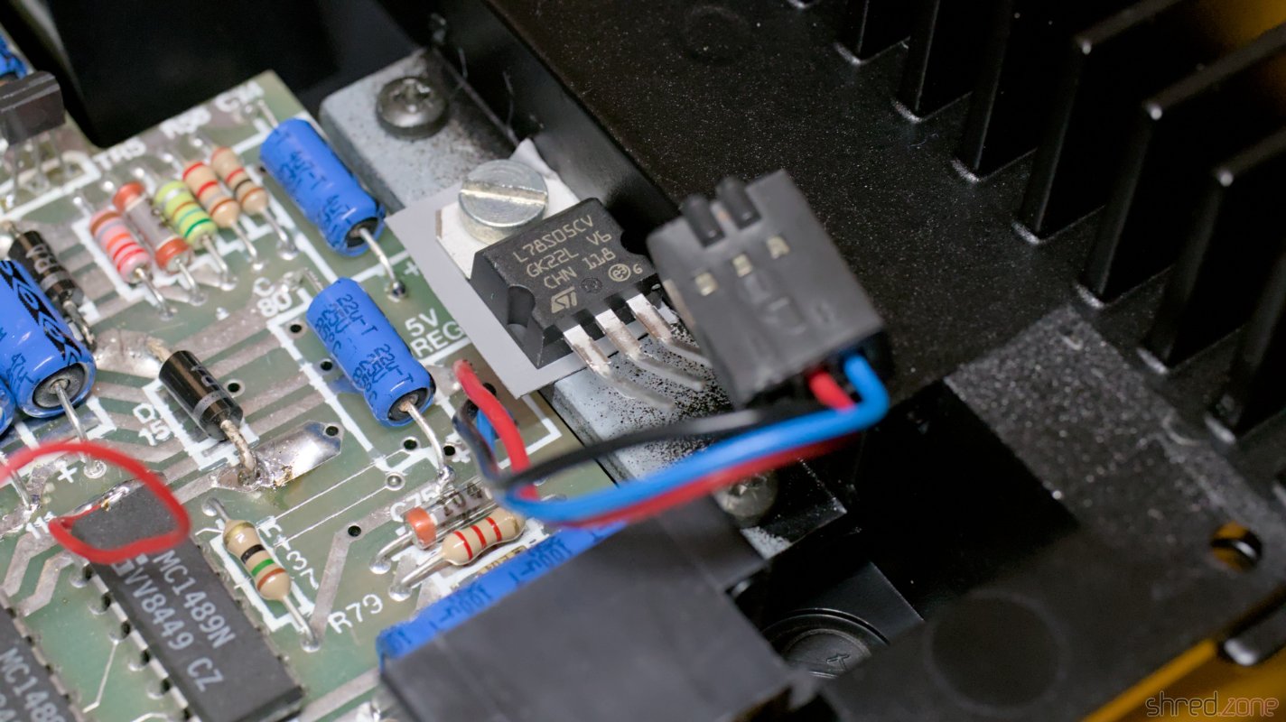
The 7805 voltage regulator is rated at 1A, and is working at its load limit on the 128K. This is the reason for the big heat sink on the right side. I replaced it with an 78S05, which is a drop-in replacement that is rated at 2A and stays considerably cooler.

I was lucky here, because in the past, someone had already replaced the 7805 with a LM1085. It is rated at 3A, but has a different pin configuration. If I had replaced it blindly, it would have killed the machine. You should always be prepared for nasty surprises when restoring old machines the previous owner already tinkered with!

The new 78S05 and a silicone heat conductor. Attention: The order of the wires has been arranged for the LM1085, the connector cannot be used like that for the 78S05!

I also cleaned the case (although it was already in a very clean state). The previous owner had already replaced the keyboard membrane, but the extra keys were not working there, so I replaced it with a new membrane of a known-good brand.

The machine, recapped and modified.

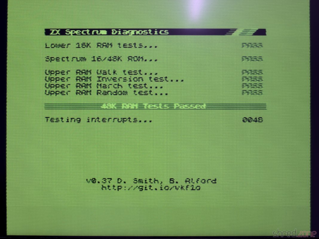
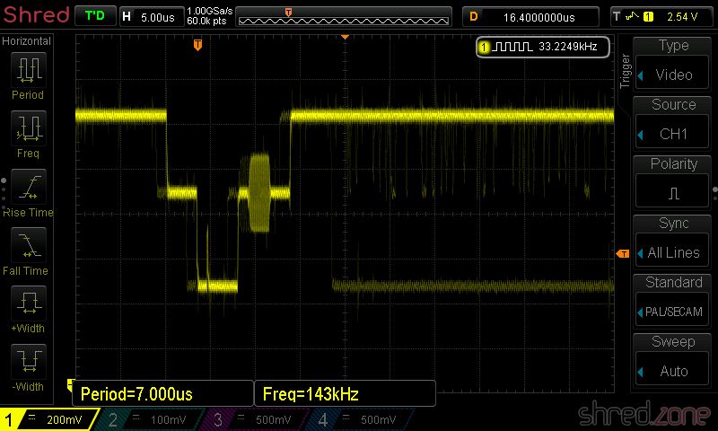
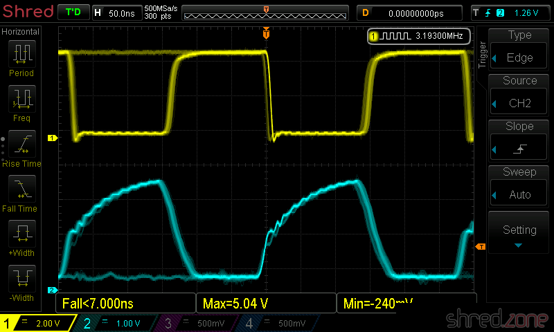
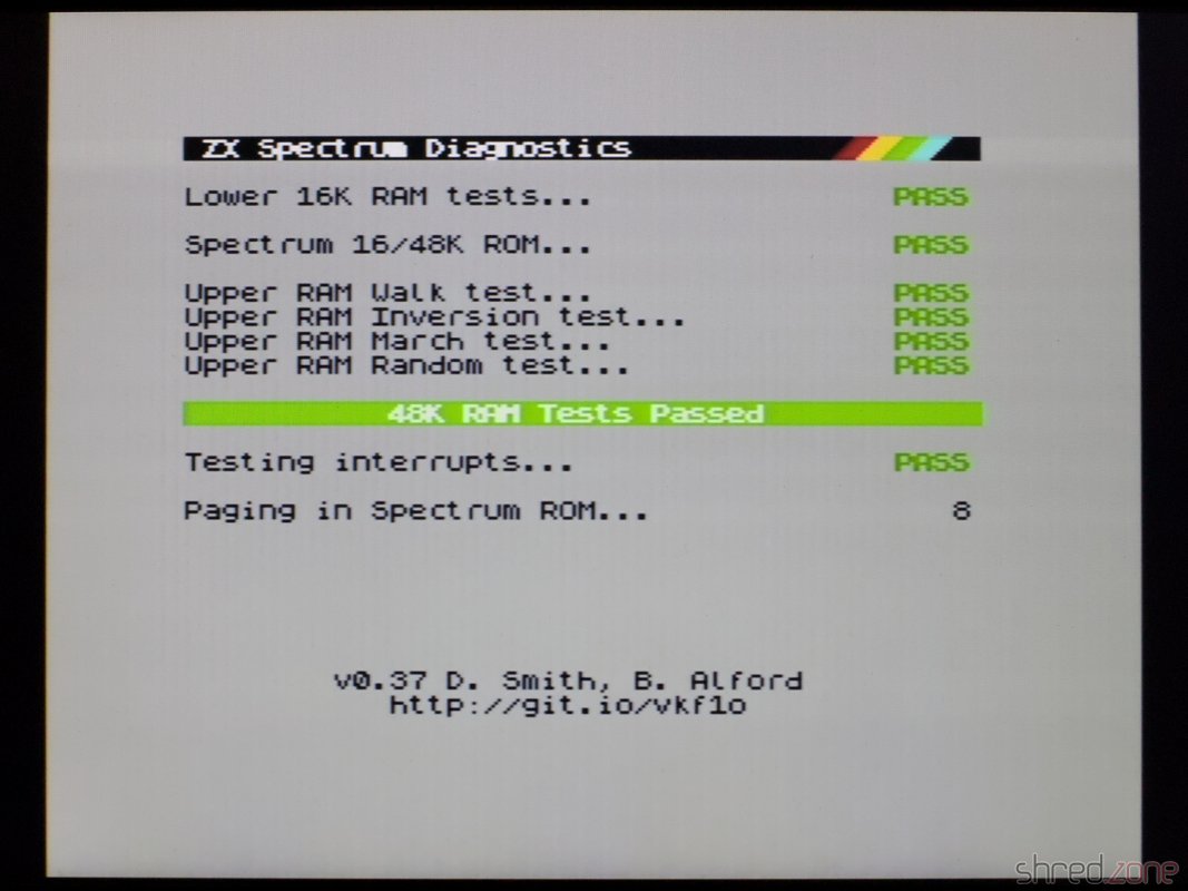
The next diagnostics run showed that all tests were still green. Also the picture interferences were mostly gone (except of some minimal jailbars that I can live with), and the AY sound is much louder.

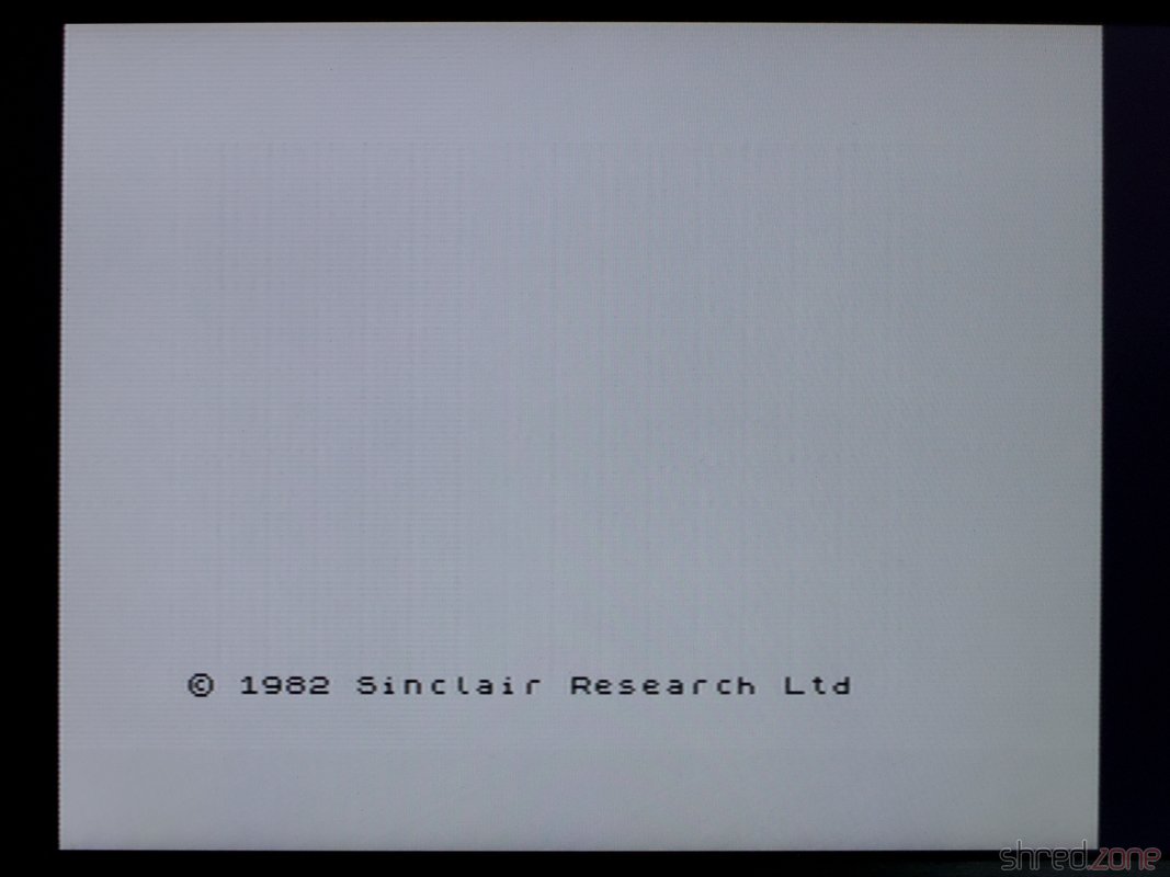
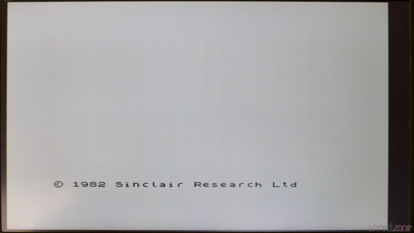
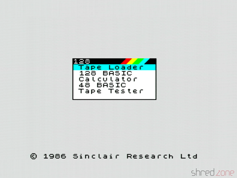
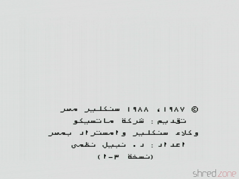
Depending on the position of the switch, the system either boots into the original ZX Spectrum 128K startup menu, or shows an Arabic boot prompt. In the Arabic version, the entire BASIC has been modified, with all texts in Arabic and written from right to left. Unfortunately I cannot read it.

The original ZX Spectrum 128K boot menu. The boot prompt of the Arabic version: "Presented by Matsico Company, Sinclair/Amstrad agency of Egypt. Prepared by Nabil Nazmi."

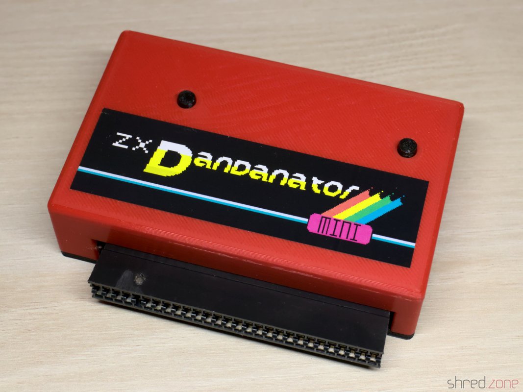
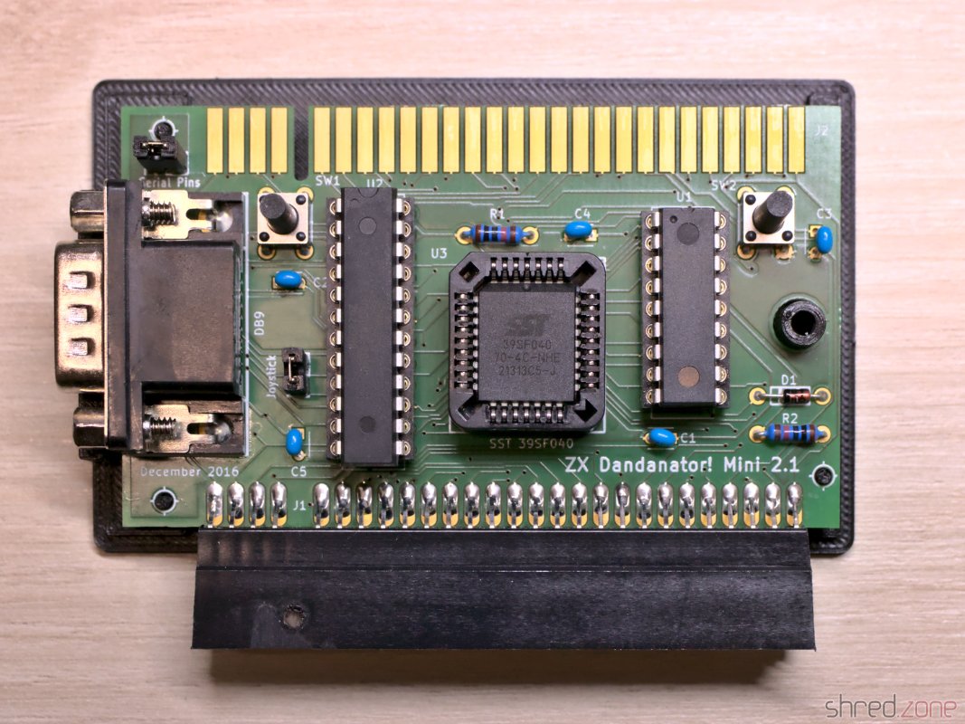
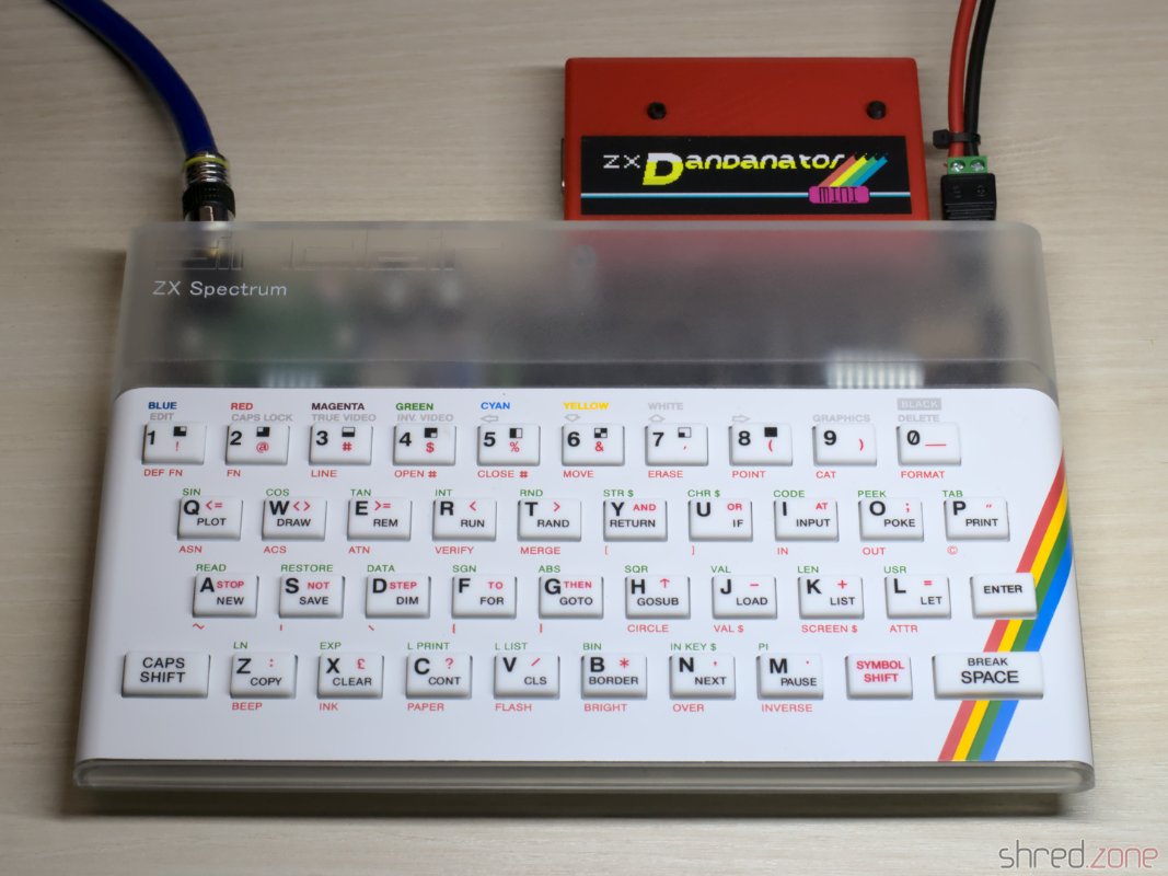
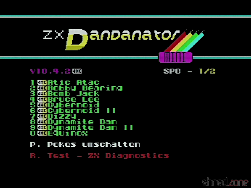
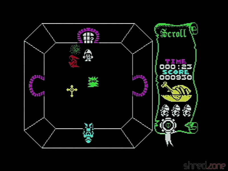
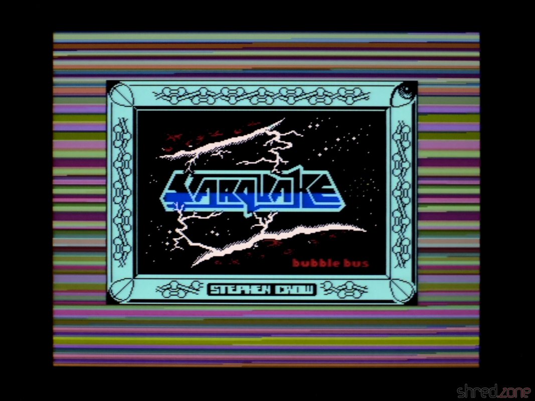
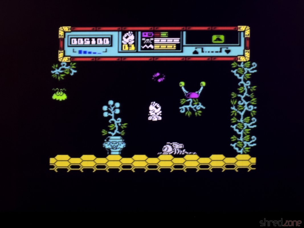
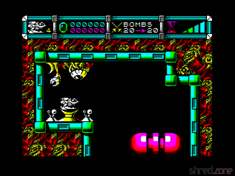
A short test with the Dandanator module also showed that games are working fine. The mandatory part of the restoration is completed!

Screenshot of Cybernoid II.

Freestyle Restoration

There were two more things I didn't like.

First was the ROM stack. The original solution switched the Vcc pins of the ROMs, so one of the chips was always powerless, but still connected to the address and data bus. To be honest, I wonder why this was working at all.

Anyway, I replaced it with a single 27C512 EPROM. On the bottom half of the memory, I burned the Arabic ROM (twice), and on the upper half, I burned the original 128K ROM. After that, I modified the switch to pull the A15 address line (pin 1) either to GND or Vcc. This way, the EPROM is always powered and the desired operating system is selected by an address line. I also upgraded the original Arabic ROM version 1 to the latest version 3.1 I could find on the web.

Of course I will keep the ROM stack. Mainly for licensing reasons, but also so that the original solution can be restored if desired.

New single-EPROM solution.

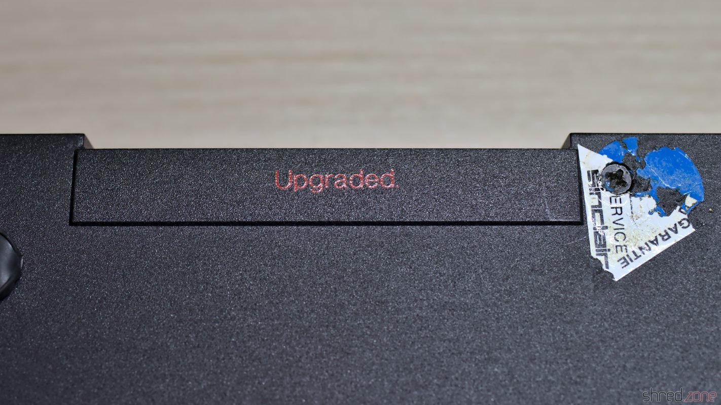
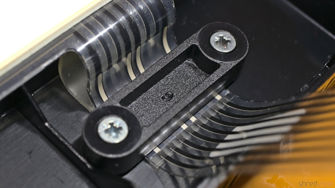
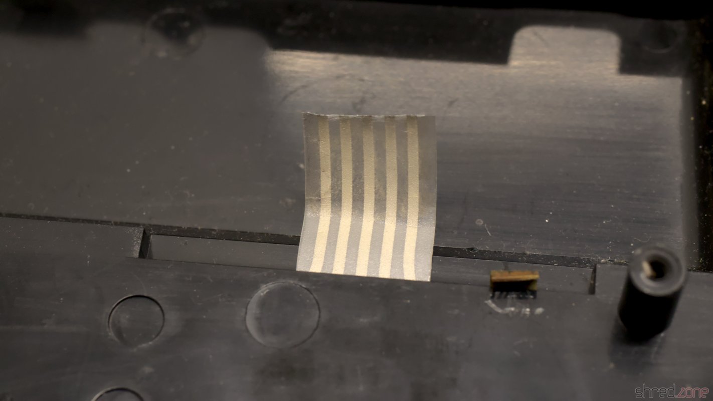
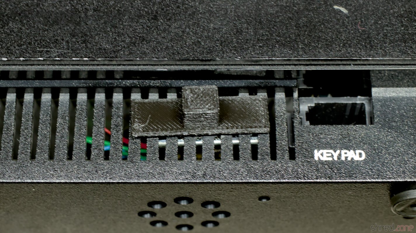
I also didn't like the optics of the naked switch at the front, so I 3D-printed a small switch cap that also covers the screws.

There are a few more things that could be done:

  • I could also rewire C126 (as mentioned in Adam's blog article above), to remove the sound signal from the RGB output.
  • Due to a bug in the original PAL10H8, the system crashes just by reading the $7FFD port address. There is a fix that also removes a "rain" effect caused by refresh data on the bus.
  • The original ULA can be replaced with a vLA128, as a replacement if broken, or if the precious original part should be conserved.
  • Dave Curran reverse engineered the numeric keypad. An ambitious tinkerer could make a DIY keypad replica.
Building a ZX Dandanator Mini

The ZX Dandanator Mini in its printed case. The main way to load software into the ZX Spectrum was via audio tapes. There have been floppy drive extensions and Sinclair's proprietary Microdrive solution, but audio tapes were cheap and ubiquitous, and cassette recorders could be found in virtually every household.

The downside was that it was uncomfortable. Tapes are slow. It took several minutes to load a game into the machine. If you had a "collection" of multiple games on one tape, you first had to wind it to the correct position. When I got my first Amiga with floppy drive, I never really looked back to those times when I had to use audio tapes.

Today I own a couple of ZX Spectrums, but I don't have a tape recorder anymore. To load software into the machine, I usually use my PC's headphone jack and tzxplay. But there is a more elegant way. The ZX Dandanator Mini by Dandare is an extension with 512KB of Flash memory where you can store your most favorite games. A boot menu permits to select one of these games, which is instantly loaded into memory. It also provides a Kempston compatible joystick port.

When I started to build my ZX Dandanator Mini, I found that the documentation of the project left a few questions open. I hope my comprehensive blog article will help others to build their own one.

Parts

It only needs a few components. Fortunately, the Dandanator's bill of materials is quite short, and all the components are easy to find, maybe except of the edge connector.

  • 1x GAL 22V10 (+ DIP20 socket)
  • 1x PIC 16F1826-I/P (+ DIP18 socket)
  • 1x SST 39SF040 Flash ROM (+ PLCC32 socket)
  • 1x 1N4148 (TH)
  • 2x 10kΩ resistors (TH)
  • 5x 100nF ceramic capacitors (TH)
  • 1x D-Sub connector, 9-pin male, right angle, Europe style (e.g. this one)
  • 2x pin headers, 2-pin
  • 1x jumper
  • 2x 6 mm tactile switches (17 mm tall if you use the 3D printed case)
  • 1x PCB (Gerber files are here)
  • 1x ZX Spectrum edge connector (can be found in retro shops, online marketplaces, or just DIY)
  • 1x 3D printed case (optional)

You will need a programmer that is able to flash the PIC, GAL, and Flash ROM (e.g. XGecu TL-866II Plus with PLCC32 adapter). I also recommend a good PLCC chip puller.

Classic GALs are out of production, but can still be found as NOS parts in online marketplaces. A replacement that is still produced is the Atmel ATF22V10C-10PU. If you use that one, you will also need a 3.3kΩ 6-pin bussed resistor array. More about that below.

Assembly

The assembly is straightforward. You start with the flattest components and work your way up to the tallest. There are no SMD components, so even a soldering novice should have no problem.

Make sure the sockets are oriented correctly. Unfortunately there are no marks for pin 1 of both DIP sockets on the silkscreen. They should be oriented with the notches near the buttons, like seen on my photo. The PLCC socket should match the outline on the silkscreen.

There is no pin 1 marker for the orientation of the DIP sockets on the silkscreen. The notches are on the side of the switches.

The edge connector is usually meant to be soldered upright, not to the edge of the PCB, so you first need to bend the pins to the inside. If done correctly, the edge connector should sit centered, and all pins should touch the pads of the PCB. Also make sure to solder the connector to the correct side of the PCB, which is the one with the short pads. The connector on the other side is meant for further expansions, like a joystick interface, but you can even stack multiple Dandanators together.

If you intend to use the 3D printed case, leave a gap of about 2 mm between the PCB edge and the connector.

Make sure to solder the edge connector to the right edge. 😉

Some of the pads are close to the edge connector on the back. It's easy to spill some drops of solder on the pads while soldering. A bit of Kapton tape is a good way to protect them.

There is not much space between the vias and the pads of the edge connector.

A problem with the ATF22V10C is that it does not provide internal pull-ups at the inputs. This means that if no joystick is connected, the inputs are floating, which could lead to problems. On my system, if no joystick was connected, the first game on the list was always started immediately. A possible solution is to solder a bussed resistor array to the bottom side. The resistors are connected to pin 8, 9, 10, 11, and 13 of the ATF22V10C. The common bus is connected to pin 24. Take care not to connect or short circuit adjacent pins.

This problem should not arise with the ATF22V10B, but at the time of writing, this variant was either out of stock or ridiculously expensive.

I soldered a resistor array to the ATF22V10C. It's a 10 pin one with the unused pins cut off because I had no smaller one at hand.

While this issue likely won't occur with older GALs, the manufacturers still recommend not to let input pins open. In my oppinion, the pull-up resistors should have been a part of the Dandanator design.

The Dandanator, fully assembled. Do not bridge the "Serial Pins" (as opposed to what can be seen here).

In a final step, clean the board and inspect it for solder bridges and other errors. A short circuit can damage the power converter inside the ZX Spectrum, which is a bit difficult to repair.

The "Joystick" header is for enabling the joystick port, and should be bridged unless you plan to use another joystick interface. The "Serial Pins" header seems to be there for in-circuit programming, and should not be bridged. (It won't cause any damage if you accidentally bridge it, but it will be like permanently pushing the joystick to the right.)

When the assembly is done, the next step is to program the chips. They all are programmed differently.

Flashing the Chips

  • GAL: The fusemap can be downloaded here. If you use an ATF22V10 and the XGecu programmer, make sure to select the (UES) variant as chip type.
  • PIC: An initial firmware can be downloaded here. I have tried to flash it with the minipro software, but could not get a working PIC from it. Eventually I used the original software from XGecu, which worked fine.
  • Flash ROM: The Flash ROM contains the games and also pokes. The image file is generated by a ROM assembler tool.

The ROM assembler is written in Java, so it runs on any modern OS. If you know about Java, you can easily build the latest version from source yourself. You can also download a jar file from the Dandanator download page and run it with the command java -jar dandanator-mini-*.jar.

The ROM assembler GUI is quite self-explanatory. You can just drag&drop TAP, SNA, Z80, and POK files of your favorite games into it until the Flash memory is full. In the settings, you can change the font, language, and also use an individual background picture.

A lot of games can be found at World of Spectrum. An extensive collection of POK files can be found here.

When you're done collecting your own favorite games, create a ROM image and write it to the Flash ROM.

Let's Play

The Dandanator is connected to the expansion port of the ZX Spectrum. Remember to disconnect it from power first.

The Dandanator is connected to my renewed ZX Spectrum.

Now power on your Speccy, and press the right button on the Dandanator to reach the main menu.

The main menu of the Dandanator, with a collection of my favorite games.

You can pick a game, either by using the joystick or pressing the corresponding key, then change the pokes to be applied, and then start the game.

The games (here: Atic Atac) start instantly. No loading from tape required.

If it's the first time you run the Dandanator, it's recommended to power off the Speccy, then keep both buttons depressed and power on again. The Dandanator will then flash the latest firmware version to the PIC.

The right button will always bring you back to the main menu. No need to reset the machine anymore.

ZX Spectrum Plus Repair

Let's have a look inside a ZX Spectrum Plus this time. It's basically the same as a ZX Spectrum, but with a (somewhat) better keyboard and a reset button. However, this machine caused a few surprises.

The first surprise was that instead of a serial number, the words "Upgraded" were printed on the case. Next to it there was a (broken) warranty seal from Sinclair Germany. It was completely new to me that Sinclair had actually sold upgrade packages for the ZX Spectrum.

Instead of a serial number, "upgraded" is printed on the case.

Inside the case, I found an Issue Two board, which is a rare sight in a ZX Spectrum Plus. For an obvious reason: The Issue Two heatsink is too big for the Plus case, so the board was somewhat crammed into the case.

An Issue Two board is crammed into the case. The heatsink is twisted to its maximum angle.

As I was going to replace the 7805 with a DC/DC converter anyway, this ugly sight of the twisted heatsink would be solved soon though.

I also found that the keyboard membrane got brittle over the years, and needed replacement with a modern replica.

The keyboard connectors are brittle and broke off.

Technical Check

The very first thing I do is the composite mod. It just takes a bit of wire and a few minutes of soldering, so it's worth to invest the time even if the Speccy should turn out to be irrepairably broken. A first check showed the start screen, so everything seemed to be allright first.

The machine seems to be working.

But then I connected the diagnostics cart, and the trouble started.

This does not look good at all. All RAMs are reported as broken, and there are strange horizontal lines.

The diagnostics reported that all eight lower RAM chips were broken, and the LEDs on the cart showed that the -5V and 12V power lines were missing. A voltmeter confirmed that -5V was gone, and there were only 7V on the 12V line, so the onboard power converter was broken. Strange enough: When I disconnected the diagnostics cart, the system started again, although both voltages were still bad.

I checked the coil, but it showed no short circuit between the windings. So I replaced the usual suspects of a broken power converter: TR4, D15 and D16. I also replaced the 7805 with a DC/DC converter as planned, and recapped all the electrolytic caps. The -5V and 12V were good after that, and all diagnostic tests passed.

Green tint, pale colors, horizontal disturbances. What has happened here?

But now the screen had a strong green tint, the colors were pale, and there were visible horizontal lines.

On Issue Two boards, there are two pots for calibrating the white balance. One just needs to connect a scope to the composite line, and then adjust both pots until the signal noise is reduced to a minimum. However, I only managed to get the green tint a bit better, but it didn't disappear. Also the disturbing horizontal lines stayed. This was the best I could get out of the signal.

But why was the white balance perfect before I fixed the power converter? I later found out that the 12V are necessary for generating the color signal. While the power converter was broken, the 12V were missing, and so the display was presented in a perfect black and white. Since the start screen does not use colors, it just looked good on the first sight. When I restored the 12V line, the color signal was generated again, and the screen got tinted.

I first suspected the ULA, but the problem stayed when I swapped it with a known-good one. Then I swapped the LM1889N. The strange horizontal lines disappeared after that, and overall the colors got better, but were still not perfect.

The pots still couldn't restore a clean white. But then I found that VR1 wasn't really working well, and the signal was crackling when I was turning it. So I replaced it with a Piher one, which almost didn't fit because it is encapsulated. After that, I could finally calibrate the signal to have a minimum noise.

The result was a perfectly white-balanced picture, with the only green things being the passed diagnostics tests.

Much better: Nice colors, perfect white balance, overall good image quality.

For a test, I reinstalled the previous LM1889N, and the color issues and the horizontal lines came back. So the problem with the green screen was a combination of a broken LM1889N and a broken pot.

The repaired board: New capacitors, repaired power converter, U?? and VR? replaced.

The hardware part is done. Let's have a look at the keyboard next.

The Keyboard

The keyboard of the ZX Spectrum Plus is a bit special. On the connector side, there is no difference to the ZX Spectrum keyboard. However, the ZX Spectrum Plus has some more special keys, like cursor keys or a dedicated delete key. These keys need to do two simultaneous keypresses in the correct order. This is done by two membrane layers that are connected to each other. A keypress then closes the contacts on both layers.

These layers are interconnected at the top of the membrane connectors. So it is crucial to do a clean work there, and to make sure that the layers are properly aligned and securely fastened under the brackets. Do not overtighten the screws though. Remember that the plastic is almost 40 years old. 😉

The different layers are interconnected at the top end of the connector. It is crucial to properly align the layers and secure them firmly.

After a bit of cleaning, I could then reassemble the machine.

And that's it. Now I finally also have a ZX Spectrum Plus in my collection.

A ZX Spectrum Plus

New ZX Spectrum 48K

The original Issue 3 board, with some labels explaining the functions of the components. I got this board of a Sinclair ZX Spectrum. It must have been a ZX Spectrum Plus model before, because there was this reset wire attached to it. There were also a few labels that were explaining the functionality of the components in German language, maybe for educational purposes.

I tried to run the diagnostics, but the module didn't even start, and the D0 LED was permanently dark. There must have been a short circuit somewhere on the data bus. But instead of repairing it, my plan was to make a completely new ZX Spectrum from as many new components as possible, with reusing only the ULA, CPU, LM1889N, the coil, and the RAM chips.

So I first removed the valuable components. The stripped original board was a sad sight, but the prospect of making a new Speccy from it made it less painful.

The board, with all valuable components stripped.

I checked the ULA in another Speccy, and it turned out to be fine. From the 16 RAM chips however, only 9 were still functional. This was much less than I expected. I'm having some of those old RAM chips in my stock, but they are precious and hard to find.

A New Board

The new board and some of the components. The new replica board is made by PABB and can be ordered from PCBWay.

For the required components, I assembled a bill of materials. It contains as many new components as I could find, but some rare parts are long out of production. They can still be found as NOS parts at online marketplaces, or they can be replaced with replacement types or replicas (like the Retroleum Nebula or vRetro vLA82).

There are four wire bridges that configure the type of the upper RAM chips, and the brand of the ROM chip manufacturer. The correct configuration can be found in my bill of materials as well.

Instead of the modulator, I decided to use an S-Video mod and a 3D printed base plate. A simple alternative is to just solder an RCA connector to COMP and GND, and use it as a composite output.

After a lot of soldering, the assembly was almost completed. But before seating the valuable chips, I first checked that all three voltages (+5V, +12V, -5V) were present and within their acceptable tolerance.

The replica board, with all components soldered in, but the chips are not seated into their sockets yet.

The S-Video mod takes the place of the original modulator, but is not soldered in, but held by two screws. The screws also provide ground, so they must not be isolating. Three wires then connect the board with +5V, and the composite signal as luma. The chroma signal is connected to the positive end of C65, which must be removed first so the luma and chroma signals won't mix.

The S-Video mod mounted in place.

After that, the new board was finally completed and ready for a first test.

The completed ZX Spectrum replica board with S-Video mod.

Bugfixing

But alas, this is what I was seeing when I powered it up for the first time.

This is what we don't want to see: black and white columns.

The diagnostics showed no action on the CPU bus controls. My suspicion was confirmed when I checked the clock input of the CPU with a scope. It was just a flat line:

The CPU clock is generated by the ULA, but the clock signal was present there.

A look into the schematics shows that between the ULA clock output and the CPU clock input there is the transistor TR3, probably for amplifying the signal. Strange enough, the signal was still present at the right of R24, which is directly connected to the clock output, but at the left of R24 (which is connected to the base of the transistor) the signal was missing already. When I removed TR3, the clock signal appeared there too, so TR3 must have been the cause.

After a longer search, I found out that the Spectrum is very picky about the type used for TR3. The original ZTX313 is not in production anymore, so I used a BC548 first, which is said to be a replacement type, however not at this position. For TR3, the only recommended replacement type is the MPS2369, which is also a bit hard to find now. With that type, the clock signal was finally good (cyan: ULA clock output, yellow: CPU clock input).

And to my joy, the new Spectrum finally started up and showed the famous start screen.

Hello there, Speccy!

The next step was to run a full diagnostics check. Now I got an error that the M1 signal was missing.

Diagnostics complains that the hardware was not found.

The M1 signal is generated by the CPU, and indicates the first of four machine cycles, which is the cycle where the next instruction is read from memory. The Spectrum itself does not use the M1 signal, but a few expansions like the ZX Interface 1 need it.

After replacing the CPU, all diagnostics checks finally passed.

We are green!

So at the bottom line, all I could reuse from the old ZX Spectrum was the ULA, the ROM, the LM1888N and the coil. I was hoping for the RAM chips and the CPU, but I haven't been really lucky with them.

Test Run

Anyway, it was finally time for a test run. I connected the new Speccy to my computer, and used tzxplay to play the tape file of my favorite game, Starquake. It was loading and running fine. Also, the image quality of the S-Video output is excellent, and probably the best one can get from this old design. Only the ZX Spectrum Next has a better quality with its native, pixel perfect HDMI output.

I bought the original board without any case. But luckily, there are replica cases, keymats, membranes, and faceplates on the market, so I could assemble a brand new outerior. Of course, I chose a transparent case, so the nice black mainboard could be seen from the outside. Well, at least a bit.

And there it is, an (almost) new ZX Spectrum in mint condition.

ZX Spectrum "Portugal"

And yet another Speccy that I could buy for a good price. The seller said it was "untested", but I allege that he knew very well it was broken. It's fine for me as I mainly buy those things for the repair fun. 😁

The computer was in a sad condition when I got it. What's remarkable is that the machine was "assembled in Portugal". It's the first time I see this, and to be honest, it was one of the reasons why I wanted to have it. According to the very few information I found on the internet, those machines were intended for the Portugese and South American market, but some of them also made it to the UK and other European countries.

The faceplate was heavily bent, and a connector of the keyboard membrane was broken off. It seems that the previous owner tried to replace the membrane, but wasn't able to remove the faceplate.

The new Speccy is in a poor condition. One of the membrane connectors was broken off and missing.  It was assembled in Portugal.

That's the first hint that the machine wasn't "untested", but underwent a botched repair attempt.

I got the second hint when I tried to power up the machine, but found that it was completely dead, with all the voltages missing. The 5V is generated by an 7805 voltage regulator. It could just have died of old age. But considering the other hint, I rather guess that the previous owner has tried to power this machine with a standard 9V power supply. It has a reversed polarity, which kills the 7805 instantly, and usually damages the lower RAM chips and other components.

Let's have a look inside. There's an Issue 6A board inside, which is the final revision of the board. But besides that, there were no surprises. Anyway it's the first Issue 6A board I own, so I'm happy to have it.

An Issue 6A board, probably built around end of 1984.

The 7805 regulator is definitely broken, but I would have replaced it with a Traco Power DC/DC converter anyway. After I replaced it, the 5V line was back. To my surprise, the 12V and -5V lines were also back, so at least there was no further damage to the power supply.

I did my usual composite mod. Then I connected the computer to my monitor and powered it up to find out what else is broken. To my surprise the start screen appeared, and the Diag ROM also found that all RAM chips are working.

The Speccy just booted up. The Diag ROM found no further defects.

Okay, so much for the "repair fun" I was hoping to get. On the other hand, this board has a second custom chip, the ZX8401, also known as ZXMUX chip. If it would have been damaged, repair would have been a lot more difficult. Not impossible though, since the ZXMUX can be simulated by a few standard SMD chips.

Now that the Speccy was repaired, I continued with replacing the electrolytic capacitors. I also found and fixed a lot of cold joints at the lower RAM chips. The refurbishment of the board was completed after that.

The board after repairing and recapping. A lot of cold solder joints.

Let's have a look at the case. The membrane connector was broken, but luckily there are new membranes available at retro shops. The previous owner tried to remove the faceplate, which is most often glued to the case. Most often, but not here. On this computer, the faceplate was just held in place by four brackets. All that would have needed to be done was to open these brackets and then easily pull of the faceplate.

The faceplate is held by four brackets that can be easily seen on the inside. All that needs to be done is to open them. The faceplate itself is not glued to the case.

Sadly, thanks to the botched repair attempt, the original faceplate was bent too much to be recoverable. It also had some visible scratches. I wished I could have salvaged it, but I decided to replace it with a new one instead. This time I took a metallic red faceplate, which looks as hot as a sunset in Portugal. 😉

My new ZX Spectrum "Assembled in Portugal".

And there it is, another ZX Spectrum for my collection.