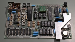
From my first days of home computing, I still have two ZX Spectrum 48K. The first one is my own one, which I restored in the previous part. This second Speccy was a donation from a friend. It was broken and written off as irreparable, so he wanted to throw it away, but I asked him to give it to me instead.
Let's find out what we have here…
Memorable Surprise
This Speccy also has an Issue Two board, but it seems to be a bit older because it has an older ULA 5C112E-3, while my own one has an ULA 6C001E-6.
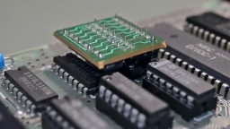
What surprised me was the tiny daughterboard that is used for IC26.
I first thought it was some kind of post-production fix for a PCB error, but it turned out to have a much simpler explanation. For the upper 32K RAM, Sinclair used eight 32KBit DRAM chips of various manufacturers. Those chips were actually 64KBit chips, but one half of the memory turned out to be defective after production, so they were sold with half of the capacity for cheaper.
To run a Spectrum, all eight of the chips need to have the defect in the same half. A wire bridge on the board then configured whether the "upper" or "lower" half of the RAM was to be used. For the OKI M3732 chips that were used on this board, the internal memory cell addressing is a bit different though. Let's put it that way, on these chips either the "left" or "right" half was defective. The tiny daughterboard just takes care of the necessary modification on the address lines to run the OKI chips. Maybe they have just been the cheapest around when Sinclair produced this batch. Starting with the issue 3 boards there were jumpers for the OKI chips, and the daughterboard was not needed any more.
Damage Assessment
In order to see anything, I first did the "composite mod" that I also did on my other ZX Spectrum. It just needs a wire and a few minutes of work, so it is well invested time even if this ZX Spectrum actually turns out to be irreparable.
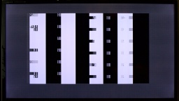
After that, I connected the Speccy to the TV, took a deep breath, and then turned on the power.
Yes, this computer is definitely broken.
New Coil
The first thing that should be tested on a broken ZX Spectrum is if the voltages are correct. The 4116 RAM chips need three of them: +5V, +12V, and -5V. The +5V were there, but instead of +12V I only got +7V, while the -5V were completely missing.
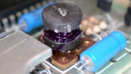
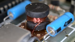
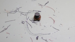
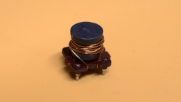
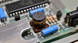
With further checks I found the culprit: the coil was shortened. And there must have been a lot of heat involved, as the insulation plastics was completely melted and got a dark purple color. The left photo shows this coil, the right one shows a good coil for comparison.
That kind of damage usually happens when an expansion cartridge is removed while the ZX Spectrum is still powered, causing a short circuit on the power lines. This poor computer must have given one last smoke signal before its decease.
The coil was custom made for the Spectrum. One can still get remakes today, but they are quite expensive. So why not just wind a new one myself?
First I thoroughly removed all the old copper wire and the charred insulator plastics. I was hoping that I could just unwind the old coils and count the number of windings, but the insulation was melted to a single lump of plastic. The wire eventually tore, and I had to use a cutter to get the remains off the ferrite core. When I was done, it looked like the coil just exploded on my desk.
Luckily, the circuit diagram gives us all the information we need to know.
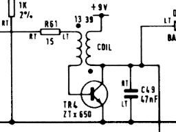
The original coil wire had a diameter of 28AWG (or 0.32mm), so we need insulated transformer copper wire of the same strength. For the inner coil we need about 30cm of wire, for the outer coil about 100cm.
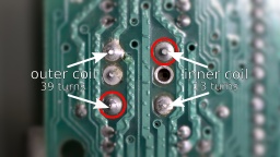
First we start with the inner coil. Wind a bit of the wire firmly around the pin marked in red on the next photo, then do 13 turns around the ferrite core, then wind the wire firmly to the other pin. The windings on the ferrite won't need to be perfect, but should still be as tight as possible. I recommend to rewind the inner coil even if it appears to be intact, as the insulation might already be damaged.
After that, we do the same with the outer coil, having 39 turns. It is important that both coils are wound in the same direction. It doesn't matter whether both coils are wound clockwise or counter-clockwise, as long as you use the same direction for both coils. The original coils are wound counter-clockwise when looked from above.
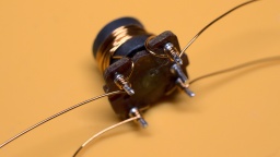
Finally, use a lighter to remove the insulation on all four pins, then use flux and a bit of solder to fix the wire ends to the pins. Now check with a multimeter. Both the primary and secondary coil should have less than 1Ω, but there should be no resistance between both coils.
Now the coil can be soldered to the board again. The fifth pin serves as a key for the correct orientation.
A shortened coil always causes secondary damage, so I preemptively replaced the components that usually fail as well:
- TR4: It can (and should) be replaced with a ZTX651, which is stronger and more reliable. They can still be found at good electronic retailers. I was researching for a standard transistor as replacement, but even though there were some types, the ZTX651 was always the strongest recommendation.
- TR5: The original type is not available any more, but can be replaced with a ZTX751 or a standard BC557 (which must be mounted facing in the opposite direction).
- D16: This can be any standard 5V1 Zener diode.
After that, I connected it to power, and (to my surprise, to be honest) all the three voltages were back and correct.
What's Next?
The picture on the TV was still unchanged, but I had already expected that more components would be damaged.
I checked the temperatures of the ICs with my finger. If you try this at home, be very careful because a broken chip can get so hot it can easily burn your skin within a second.
The ULA got warm, but that's normal. The CPU also got a bit warm, which wouldn't be a surprise on modern computers, but the Z80A is supposed to stay cold. I unsoldered it, and replaced it with a 40 pin socket and a used SGS Z80A CPU that I once recovered from a broken ZX-81.
I powered it up again, and it just worked! 🎉
So there was just a burnt coil and a broken CPU. This repair was much easier than I had expected.
Finishing Works
Like on my other ZX Spectrum, I first replaced all the old electrolytic capacitors. I also used a fresh 7805 voltage regulator, and thermal paste for better cooling.
My first Spectrum got a transparent case and a chrome faceplate. For this ZX Spectrum I decided to keep the original look, so I just replaced the broken keyboard membrane. The old faceplace had some visible dents and scratches, so it was replaced as well. I then washed the original case in warm water with a bit of dish detergent, and then put it all back together.
And that is the story of the two sisters who got a nice makeover, and are now fit for the next 30 years. 🙂
