While I was restauring an Amiga 1200, I noticed that on that machine, the right and middle mouse buttons did not react on both ports. Checking it further, it turned out that it was working with an original Amiga mouse, but failed with my YAMI mouse interface. The mouse interface could not be the cause though, as it is actually working reliably for decades on all kind of Amigas, including an Amiga 1200.
The problem is already known to the community, and also seems to affect other mouse interfaces. The mitigation options I could find so far were:
- Just use the original Amiga mouse. 😉
- Modify the mouse interface. There is a "fixed" version available for some of them.
- Use a "FixRMB" tool. This tool needs to be started first though, so it won't work for reaching the boot menu or in games. It also requires a mouse interface with internal pull-up resistors. (YAMI does not have those, for example.)
- Some said they were lucky with replacing the Paula chip, but it requires experience in soldering.
None of these options is really appealing to me. I want this Amiga to work like all the others. So I tried to figure out what is the actual problem here, and how to fix it properly.
The middle and right mouse buttons are connected to the POT pins of Paula. These inputs are actually made for analog joysticks, and provide a very simple ADC. The analog joystick charges a capacitor, while a counter inside Paula is taking the time. As soon as the voltage of the capacitor reaches a certain level, the timer is stopped. The position of the joystick can be evaluated by the time it needed to charge the capacitor.
But there is also a digital mode, which is used for mouse buttons. If enabled, a resistor inside Paula pulls up the POT line. If the mouse button is pressed, the mouse switch pulls the line to LOW, which can then be read from the Paula registers.
When an original mouse was connected, the POT line was pulled to 0.9V while the button was depressed. However, when the mouse interface was connected, the line was only pulled to 1.1V. It seems like a tiny difference, but for this Paula chip, it already makes the difference between "button pressed" and "button released".
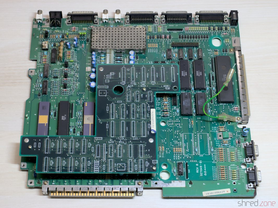
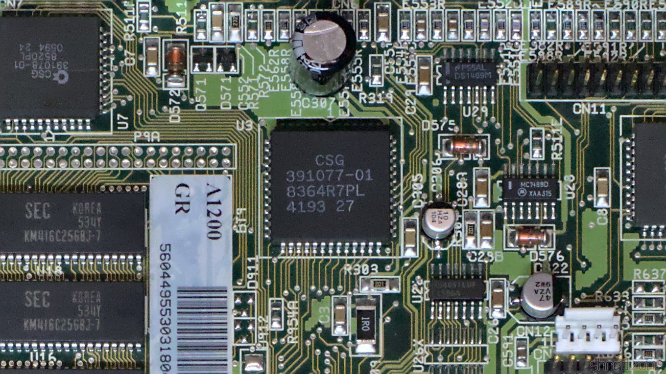 Only a certain batch of Paula chips seems to be affected. This is the reason why this problem does not occur on all Amiga 1200, but presumably only on some 1D.4 boards. This is also the reason why replacing the Paula chip is fixing that issue. On my board, a "CSG 8364R7PL" with date code 4193 is used. I also heard of one more case with a Paula chip of the same production week.
Next question: Why only Amiga 1200 models seem to be affected by this issue, although it is likely that the affected Paula batch was also used in Amiga 4000 production? When comparing the schematics of both machines, there is a notable difference. This is a simplified extract of the joystick or mouse port:
The difference is in the parts marked with a red circle. They are used as EMI filter. For the Amiga 4000, Commodore has used ferrites there. It is basically just a wire inside a ferrite bead, giving a resistance of 0Ω at low frequencies. In the Amiga 1200 (and Amiga 600) though, Commodore used standard 68Ω resistors, presumably to cut costs.
Together with the pull-up resistor inside Paula, this resistor works as a voltage divider. The switch inside a classic Amiga mouse pulls this divider to ground, giving 0.9V at the POT input, just enough to get detected as LOW.
The mouse interface does not have a real switch though, but a logical output. For example, the PIC16F84 that is used in the YAMI interface provides a LOW voltage of 0.6V. Now the voltage divider gives 1.1V at the POT input, which is interpreted as HIGH by Paula.
I could not find out if the pull-up resistor inside Paula has a lower resistance in that batch, or if there is a different threshold for detecting LOW levels. Both would be possible.
To fix the problem on my Amiga 1200, I replaced the 68Ω resistors E353R, E354R, E363R, and E364R with the SMD 1206 ferrites that are used in the Amiga 4000. They are a bit bigger than the 0804 resistors, but can still be soldered straight to the pads.

This is just a minor change to the hardware that could be done even by soldering novices (at least rather than unsoldering a PLCC chip). After that change, the mouse interface was working too.
Make sure to replace the resistors with ferrites, not the capacitors next to them!
PS: If you found this article because your Amiga is also having the problem, please send me the date code of your Paula chip. Maybe we can find a pattern of "bad" date codes. Thank you!
PPS: Commodore did the same trick on Amiga 600 machines, so if you have trouble with the right mousebutton on your A600, it's worth a try to replace E353R, E354R, E363R, and E364R.