 With the recent AmigaOS 3.2 release, and the prospect of further updates, it may be interesting to burn own EPROMs for the Amiga. Luckily there is no need to buy expensive equipment any more, as EPROM burners and erasers became affordable. This article explains how I burn Amiga EPROMs at home.
Shopping List
First of all, we will need fitting EPROMs of course. These types are compatible to most Amiga models:
- AMD AM27C400
- Macronix MX27C4100 [sic!]
- STMicroelectronics M27C400
It is important to pick parts with an access time of 200 ns or faster. Models like the Amiga 4000 can even be jumpered to an access time of 160 ns. EPROMs with 120 ns (or less) are easy to find, and definitely on the safe side. Note that Macronix truncates the trailing zero, so a MX27C4100-12 actually has 120 ns access time.
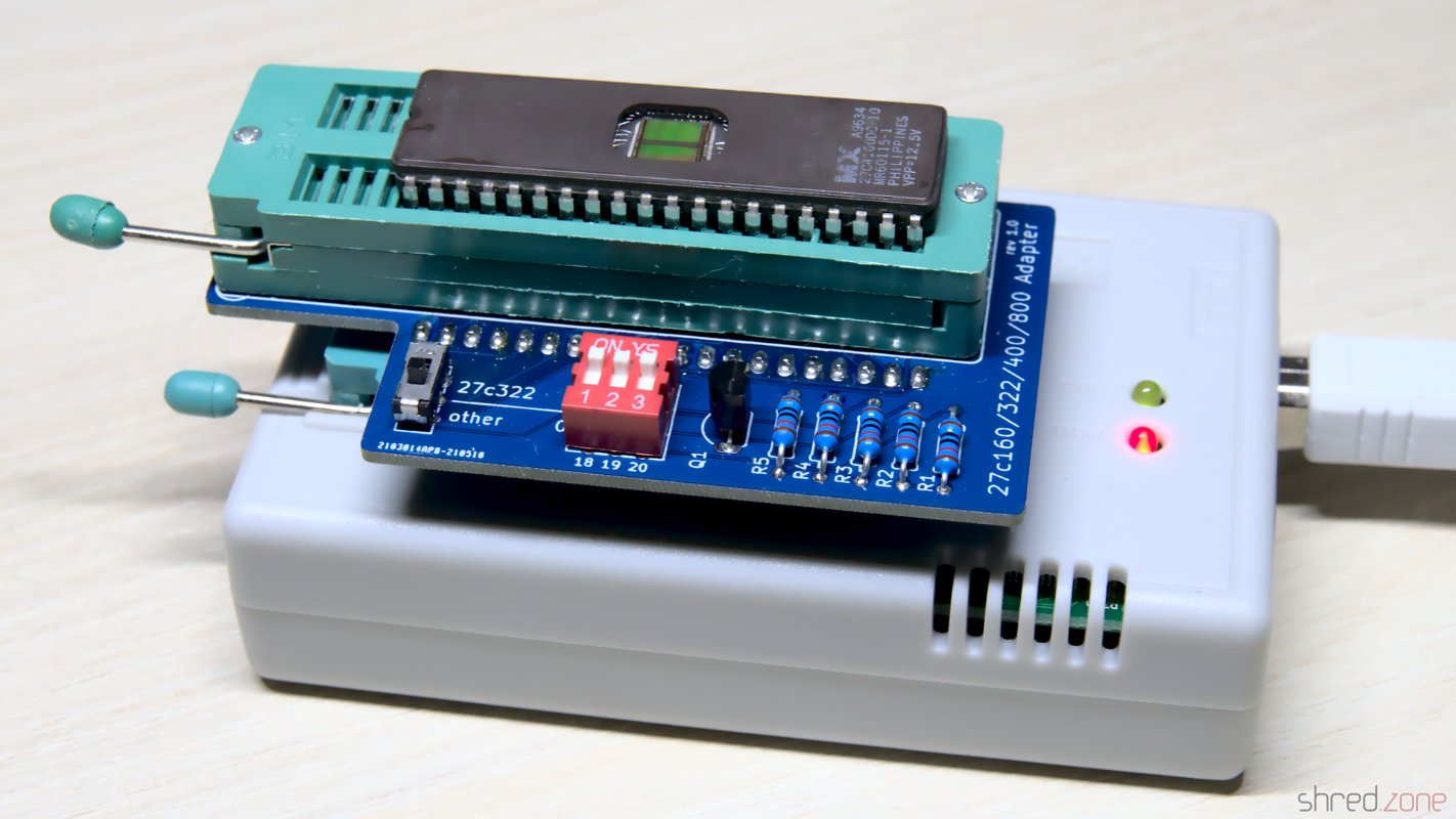
For burning the EPROMs, I use an XGecu TL866II Plus programmer and a 27C400 programming adapter.
Unlike modern flash memory, EPROMs cannot be erased electrically, but are erased by exposing the chip behind the quartz glass window to a strong UV light source. For this reason, an EPROM eraser is also recommended. Note that there are OTP-ROMs without that window, they cannot be erased at all.
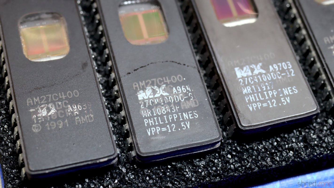 None of these EPROM types are still in production. You might still find sources who sell NOS parts, but usually all chips on the market are refurbished. I am a bit careful with chips that look too new, or are claimed to be made by AMD. It is likely that these are just Macronix chips that were painted black and then laser-engraved with a fake AMD label. A cotton bud and a bit of nail polish remover will quickly reveal the scam.
These fake parts are perfectly fine. They are just sold at a higher price because of the alleged noble AMD origin, so you might as well order the Macronix chips directly and save money.
Preparation
Before burning a ROM dump, all even and odd bytes need to be swapped. For Amiga models with two ROM sockets, these dumps also need to be split into separate images for the upper and lower word. To make things even more complicated, a 256KB ROM dump needs to be duplicated to fill the entire memory space of a 512KB EPROM.
Luckily, the AmigaOS 3.2 CD already provides *.bin files that are ready for burning. For plain ROM dumps (those that can be used in emulators), my tool pynaroma can be used for byte-swapping, splitting, and duplicating.
Burning ROM
For the TL866 programmer, I prefer to use the minipro controller software. It is open source and runs on Linux, MacOS and many other Unix derivates, while the manufacturer's original software requires Windows.
The programming adapter is inserted into the programmer, and EPROM inserted into the ZIF socket of the adapter, with the notch pointing to the top, and the chip aligned with the bottom of the socket. Do not put the EPROM into the programmer without that adapter, otherwise it will be destroyed during operation.
The adapter simulates the pinout of an AM27C4096 EPROM, so --device 'AM27C4096@DIP40' must be selected. The --skip-id option must be given as well, otherwise minipro would abort the process because it detects a different type of EPROM.
For writing, the --no_id_error option needs to be used instead. By default, the AM27C4096@DIP40 profile uses a programming voltage of 13V, and a writing voltage of 6.5V. On my chips VPP=12.5V is printed, so I reduced the programming voltage with the --vpp 12.5 option. It might also be necessary to reduce the writing voltage using the --vdd option. Check the datasheet if in doubt.
The first step is to check if the EPROM is empty.
minipro --device 'AM27C4096@DIP40' --skip_id --blank_check
If it's not, it must be erased first. 15 minutes of UV light exposure in the EPROM eraser should be sufficient. If the EPROM still isn't empty after that, just repeat the process.
After that, the ROM image (e.g. amigaos.bin) can be burned to the EPROM:
minipro --device 'AM27C4096@DIP40' --no_id_error --vpp 12.5 --write amigaos.bin
minipro will automatically verify the content after burning, but you can also verify it manually:
minipro --device 'AM27C4096@DIP40' --skip_id --verify amigaos.bin
And for the sake of completeness, this is how to read the content of a burned EPROM to a ROM image file:
minipro --device 'AM27C4096@DIP40' --skip_id --read amigaos-read.bin
After burning, the window should be covered to protect the chip from stray UV light. A simple paper sticker is sufficient.