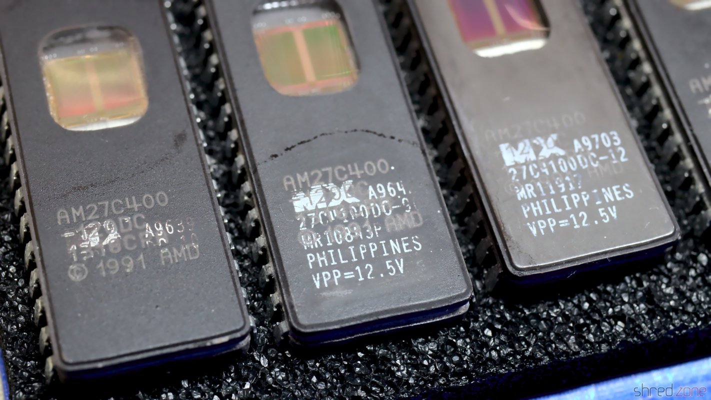
It's possible to use EPROMs to update your Amiga to the latest AmigaOS. Unfortunately these EPROMs are not produced any more, so it's becoming increasingly difficult to find these parts on the market. Another disadvantage is that a special UV light source is necessary to erase EPROMs, unlike modern Flash ROMs that can be erased electrically.
So wouldn't it be better to use Flash ROMs instead? Certainly yes, but they do not come in DIP-40 packages that fit the Amiga ROM sockets.
The Flash ROM Adapter
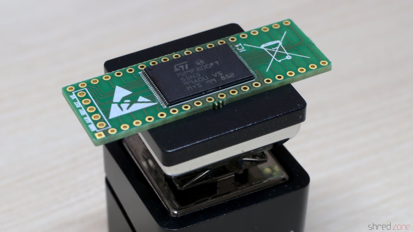 djbase kindly published the design of an Amiga Flash ROM Adapter. It can be equipped with 29F400, 29F800, or 29F160 Flash ROMs. They are available at all kind of electronic sellers, and can store up to four Amiga ROMs in a single chip.
Besides the PCB and the Flash ROM chip, you only need four SMD resistors, one SMD capacitor, and pin headers. The problem, however, is that the components are tiny, and the pitch of the Flash ROM chip pins is very fine, so this project is definitely not suited for soldering novices. Trust me. I made three of them for the bin before I was successful.
The Programming Hardware
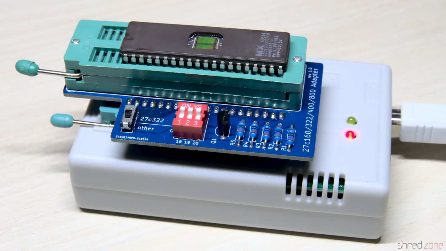
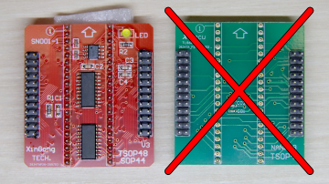
 For programming, I use an XGecu TL866II Plus programmer and the SN001 Adapter Kit. djbase also provides a special programming adapter, which is connected to the TSOP48/SOP44 base board of the SN001 adapter kit.
Note that you will need the active base board (SN001, red in the photo). The standard TSOP48 base board (green) won't work here.
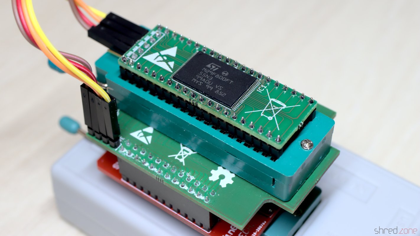
This programming adapter sandwich is put into the ZIF socket of the TL866 programmer. The Flash ROM adapter is placed into the ZIF socket of the adapter board, and the pin headers of both boards are connected according to their labels. Note that the current revision of the adapters support Flash ROMs up to the 29F160, and require five wires. I still use the previous revision with only four wires, because I like it better.
The GND pin of your flash board can be left open for the flashing process. It is typically used to connect a jumper or switch inside your Amiga, to select the ROM bank.
If you don't intend to change the Flash ROM content after soldering, you can also save the programming adapter and use the SN003 adapter instead (which often comes bundled with the SN001 adapter kit). You would then flash the Flash ROM before soldering.
The Binary File
For preparing the binary file, I use my Pynaroma toolkit. It takes care for joining multiple ROM files and the necessary byte swapping. For example, to create a ROM image of AmigaOS 2.04 and AmigaOS 3.2.1 for the Amiga 500, this command line can be used:
rom2bin -o flash.bin A500.37.175.rom CDTVA500A600A2000.47.102.rom
Depending on the flash ROM chip, you can use up to four different ROM files of 512KB each. If the ROM file has a size of 256KB, remember to duplicate it.
Once the adapter is in the Amiga, the desired ROM image can be selected via the header address lines (e.g. by using jumpers or switches). Note that the address pins of the Flash ROM are pulled-up by the adapter. This means that the last ROM file of the sequence is used when all header pins are open.
Flashing
For programming, I prefer to use the open-source minipro software over the original software by XGecu, mainly because the original software is not available for Linux.
It is important to select the correct Flash ROM type. Pick the type that you have actually soldered to your adapter. Always choose the TSOP48 package, as the programming adapter simulates a TSOP48 socket.
I use a M29F800FT, so the correct device setting is M29F800FT@TSOP48, and the command line for flashing the binary file from above is:
minipro --device 'M29F800FT@TSOP48' --write flash.bin
The Flash ROM will be erased (so there is no need to erase it before), the image written to it, and then verified in a final step.
ROM Replacement
 The Flash ROM is a drop-in replacement for the Amiga ROM. I carefully removed the original ROM from the socket by using a screwdriver with a wide blade.
After that, I put the Flash ROM adapter into the socket. The correct orientation is crucial. The adapter is put with the header having the same orientation as the notch of the original ROM.
Sometimes the holes of the socket are too small to receive the pins of the adapter. In this case the only chance is to either replace the socket, or use an EPROM.
If you own an Amiga 500 Rev. 5 mainboard and experience random crashes with the new Flash ROM, you might need to add resistors to the address lines. This can be done either via resistor packs or by using an Amiga 500 EPROM adapter that is sold at some Amiga shops.