C64 is ready

#Amiga

Amiga 1000 Restauration, Part 1

When the Amiga 1000 was launched in 1985, it was too expensive as a home computer, but rather targeted the professional graphics workstation market. The sales figures were correspondingly low. Only 27,500 units have been sold in Germany. Nevertheless, and without a doubt, the Amiga 1000 is the jewel of every Amiga collection. Now I finally had the lucky chance to get my own one.

The Amiga 1000, as I got it. The keyboard is a French/Belgian AZERTY type, with labels for the German keyboard layout.

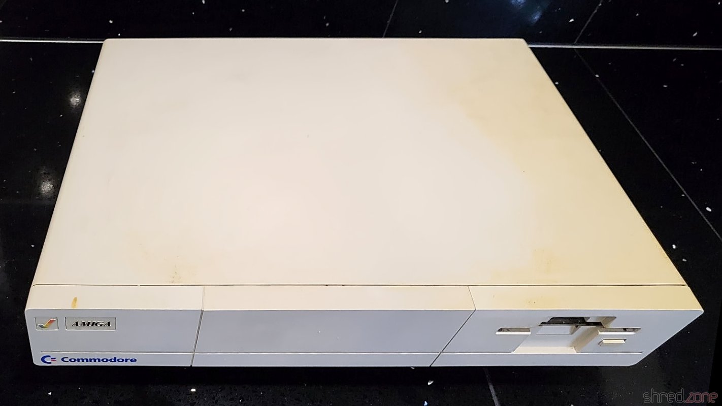
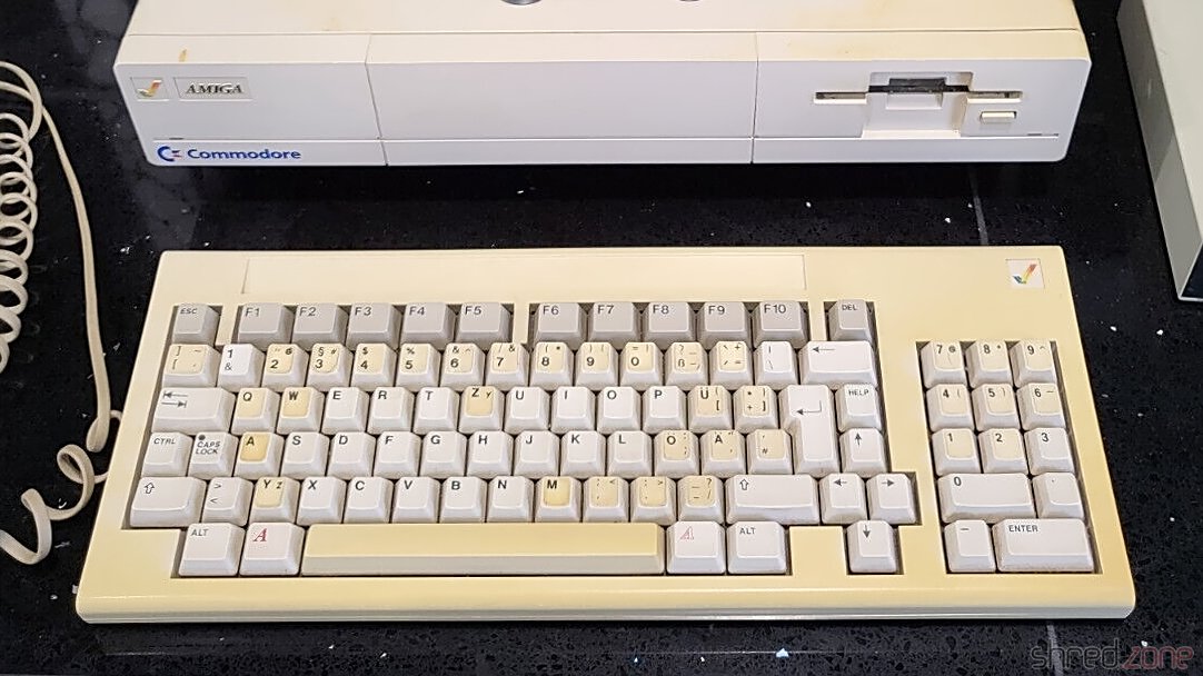
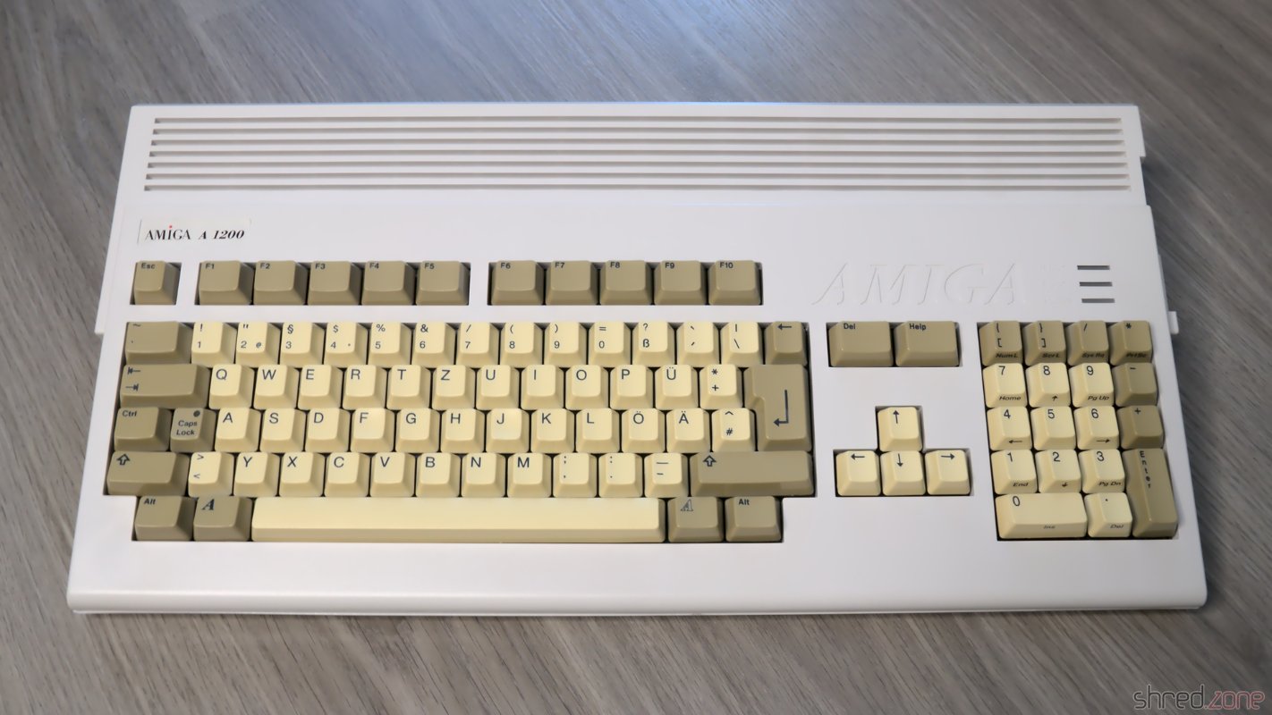
The overall state is fine, considering that the machine is almost 40 years old. The Amiga itself is only a bit yellowed, but has some heavy scratchmarks at one edge. The keyboard has a French/Belgian AZERTY layout that was changed to German layout using stickers, like it was usual for the first machines that were sold in the EU. Its case and the space bar are much more yellowed. The stickers are also yellowed, and one is missing.

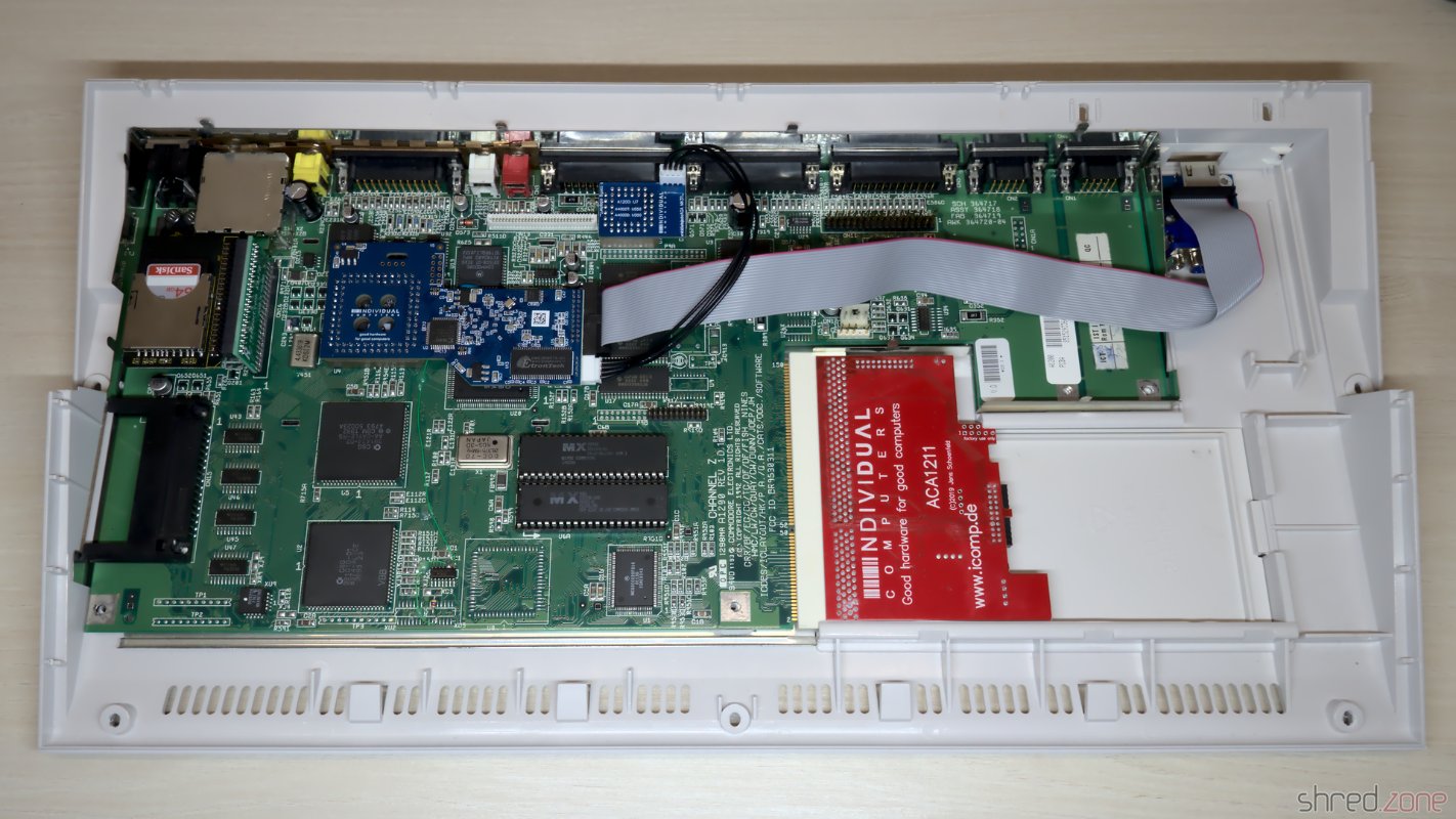
The expansion slot at the front contains a 256KB RAM module. The original mouse and the disks have been lost, but I can use any other Amiga mouse and make new disks myself.
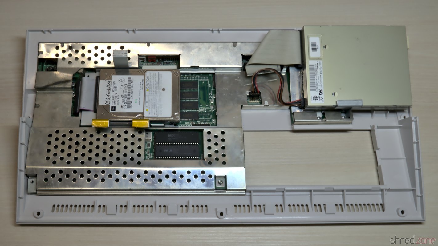
What's Inside

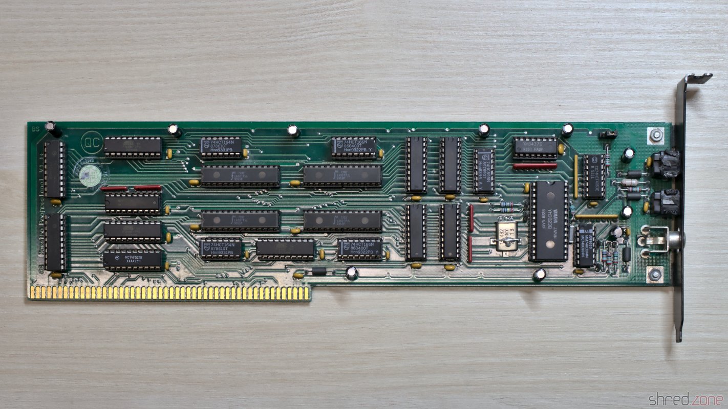
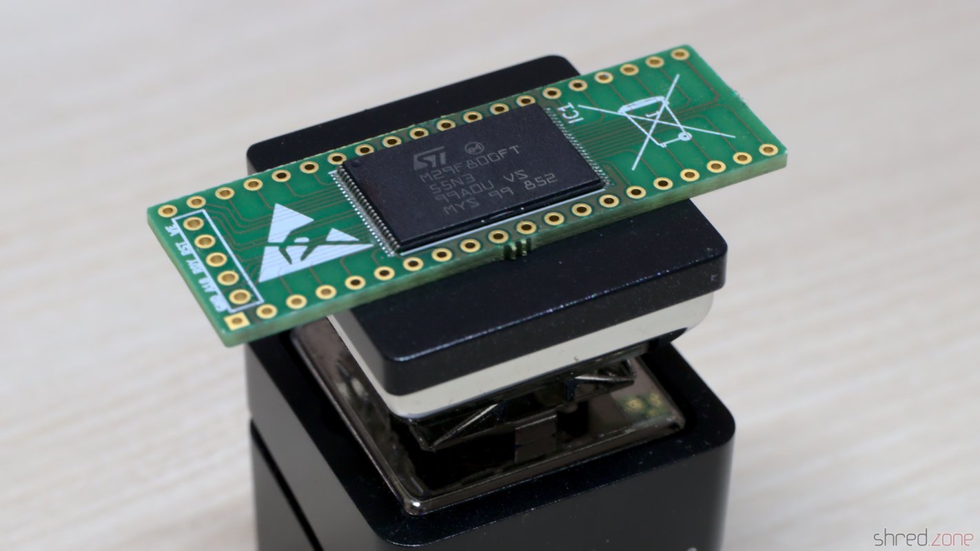
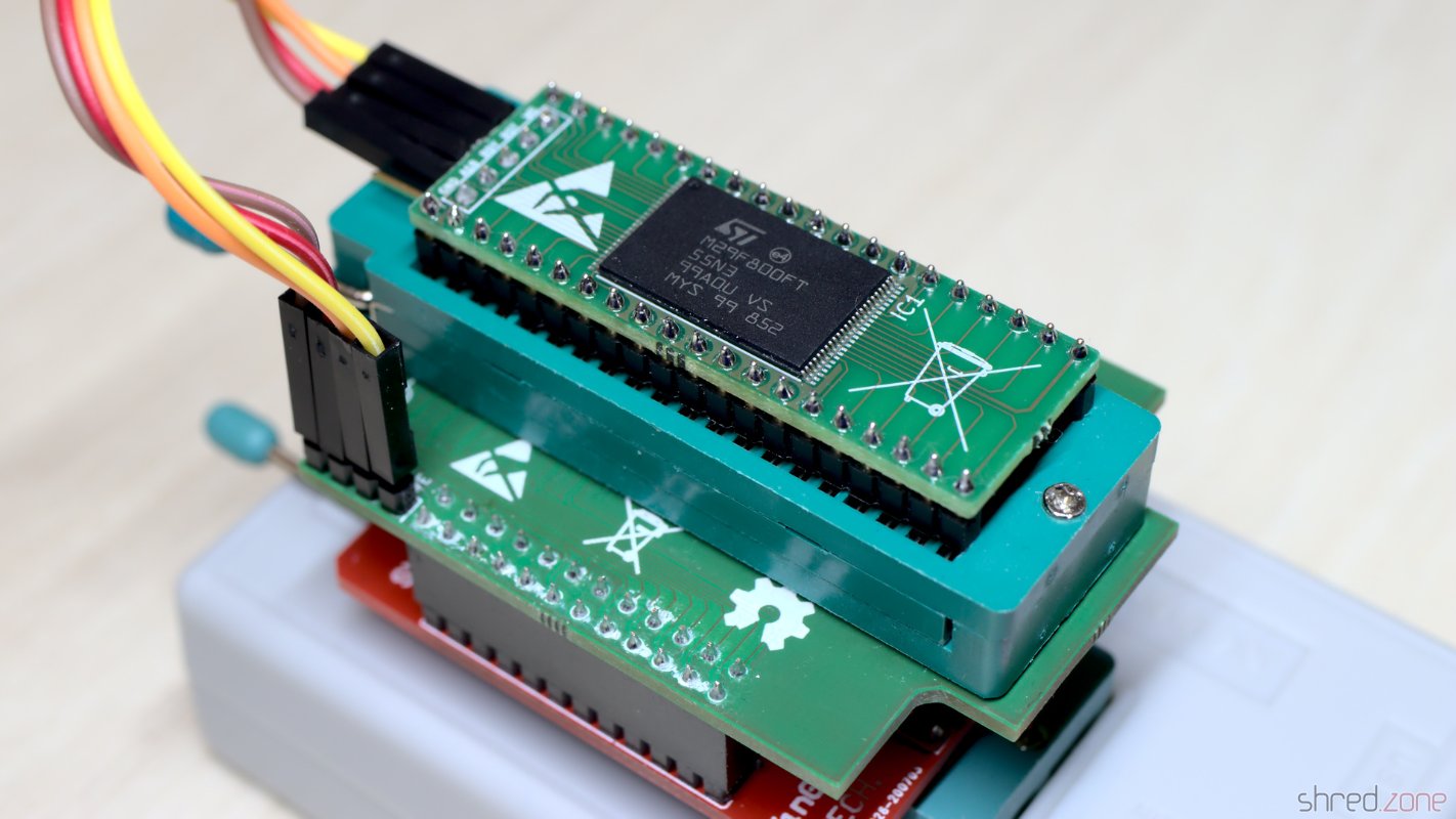
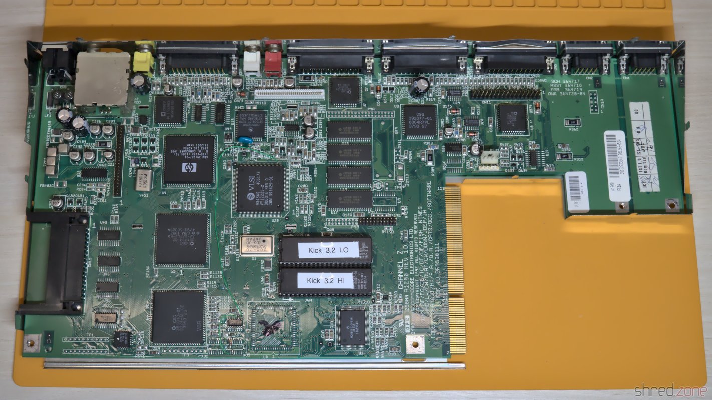
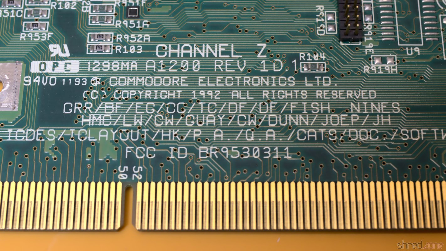
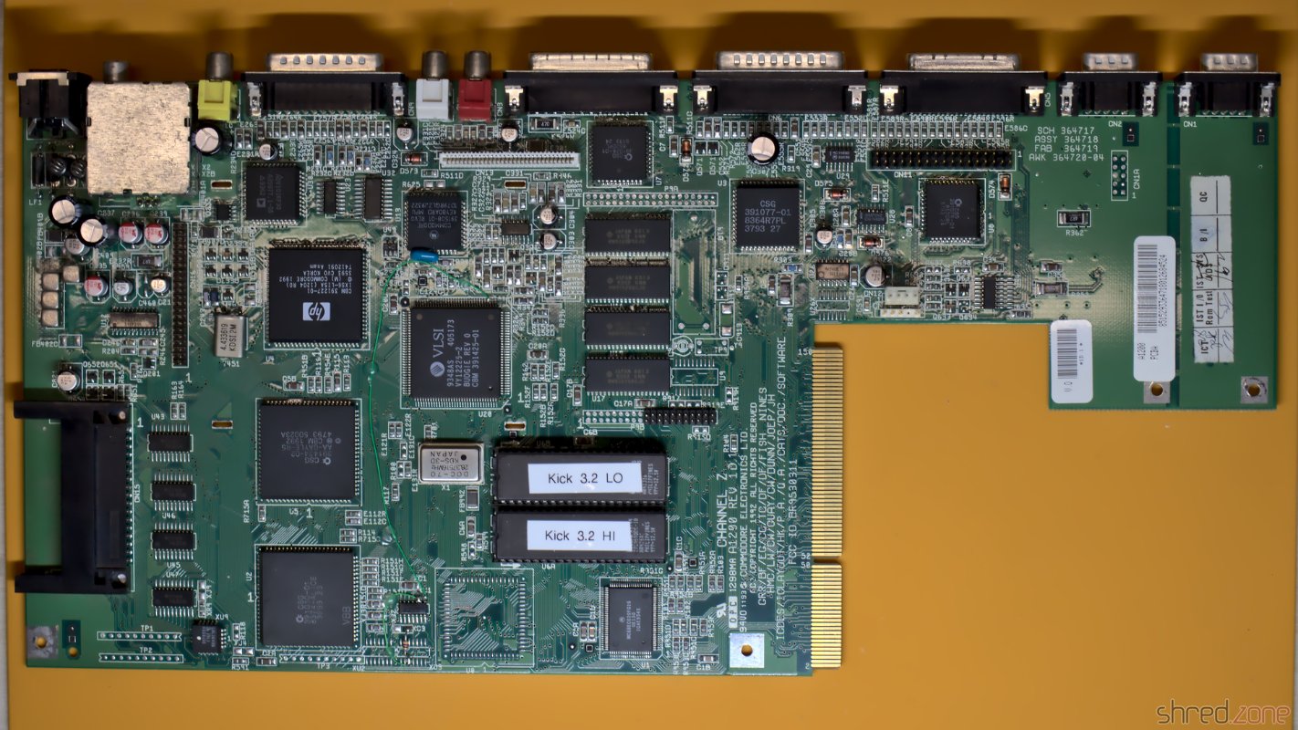
Inside I found a Rev A mainboard and a piggyback board. That extra board stores the Kickstart that is loaded from disk when the machine is powered up. Later revisions used Kickstart ROMs, and didn't need this piggyback board any more.

The mainboard, and the piggyback board on top.

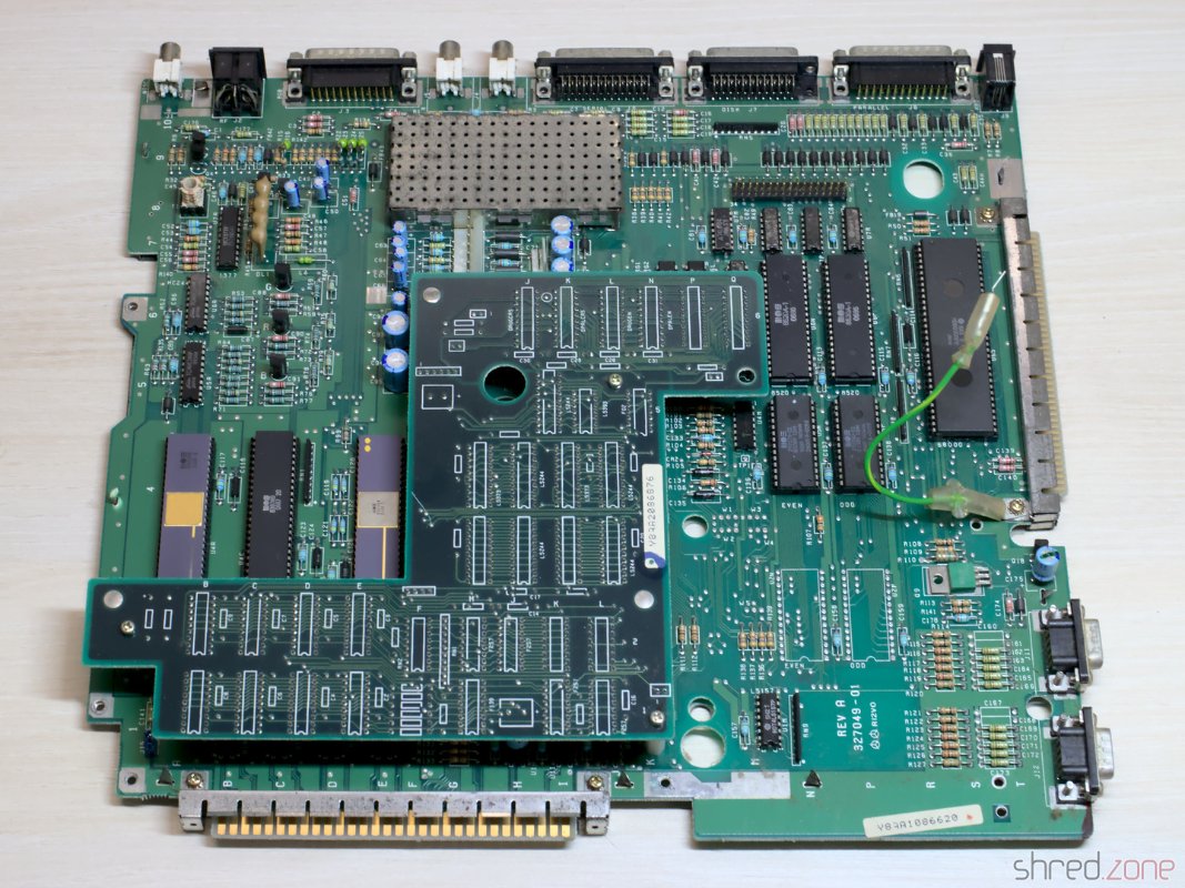
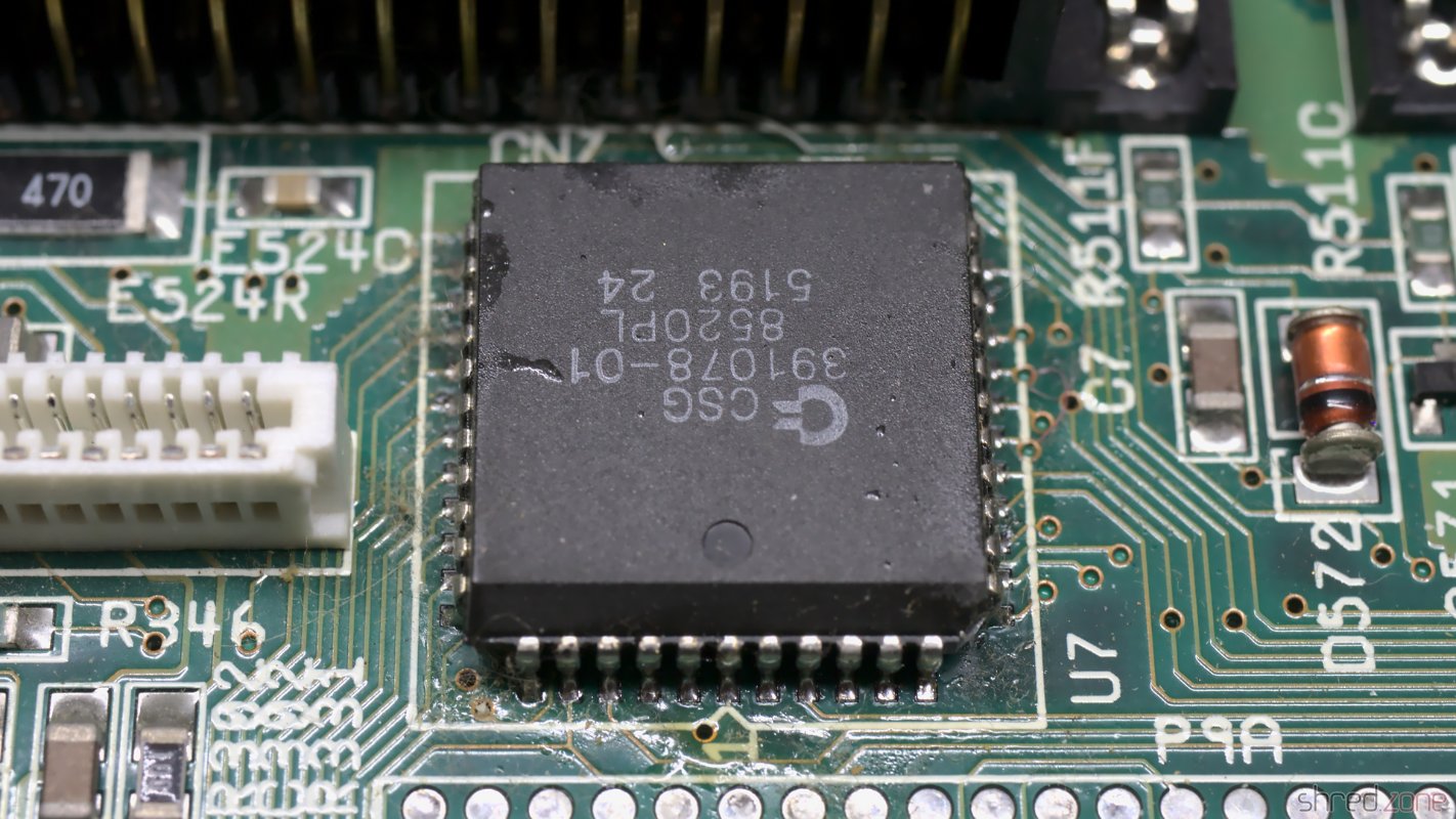
Usually all piggyback Amiga 1000 were produced for the US market. They could not run in Europe without modifications, due to different power frequencies and TV standards. My machine was produced in early 1986, presumably for the US market. One year later, it was modified for the European market. The original Agnus chip was replaced by a 8367R0 that is able to generate PAL video signals. The crystal is still the original 28.6363 MHz NTSC one though, so the video signal is not truly PAL.

The system has a Denise 8362R6, which is the first revision that is also capable of displaying the EHB mode.

Altogether, it is an early Amiga model, and very likely one of the first that have been sold in Germany.

The PSU

Generally I don't recommend to power up an old computer straight away after many years of storage. Without a visual inspection and the necessary refurbishment, the power supply could damage the computer, or components inside could blow up.

A first visual check of the PSU seemed to be allright, with no obvious damages, and no bulged or leaked capacitors. But then I found tiny cracks in one safety capacitor.

A look into the PSU. This RIFA capacitor shows signs of fatigue.

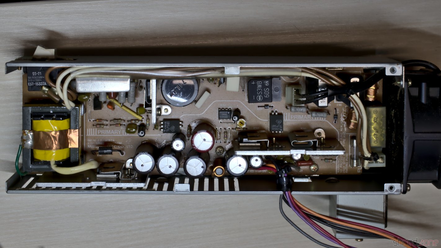
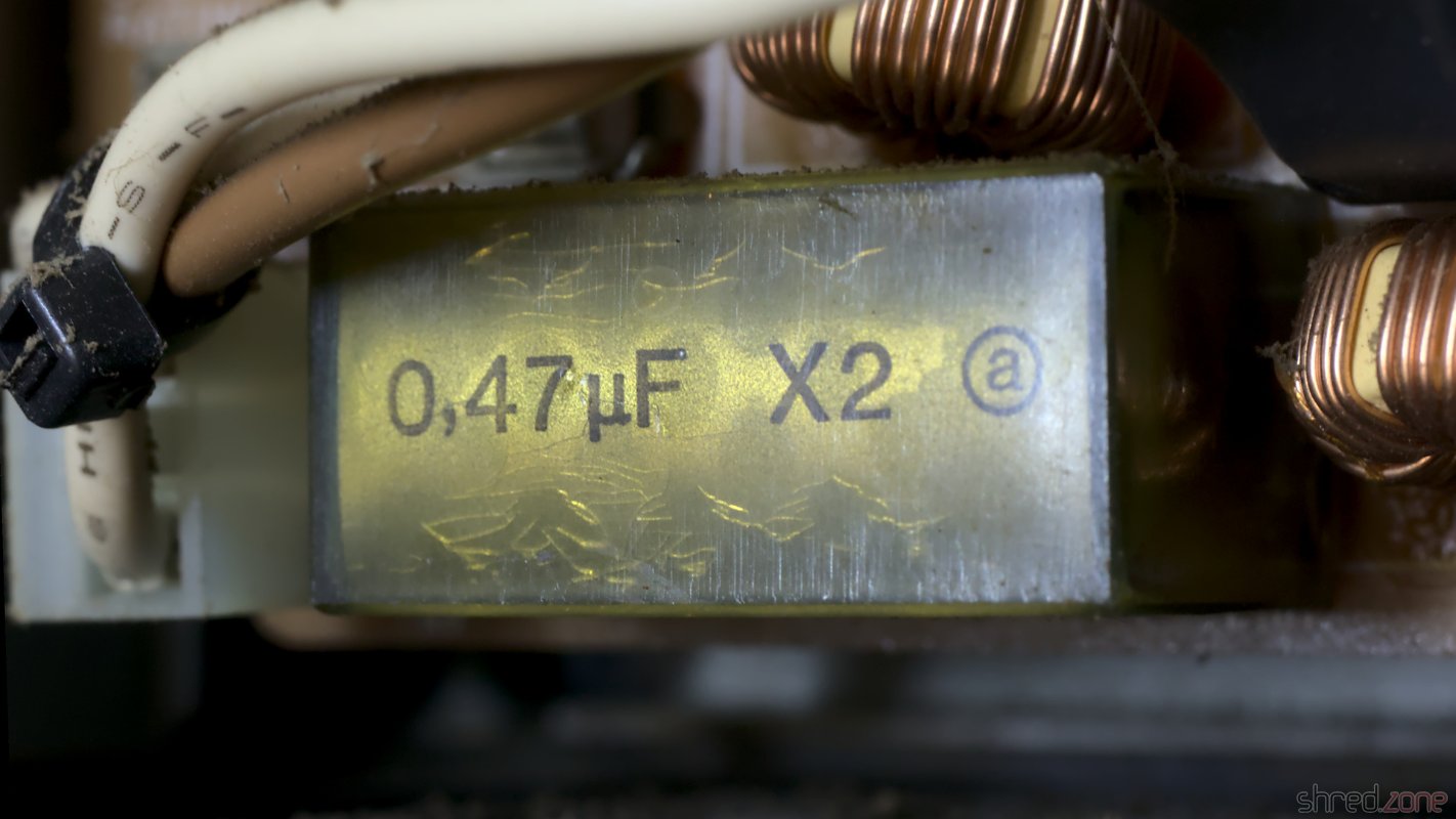
These RIFA X class capacitors are actually infamous for blowing up after many years. Their insulators are made from paper. The material gets brittle from age and thermal stress, letting in moisture, which amplifies the problem. Eventually the capacitor can crack open and go up in fumes.

It was good that I kept the PSU disconnected from mains. It is now being refurbished by @DingensCGN, a member of the A1K.org forum who has a lot of experience with Amiga PSU restauration.

The Mainboard

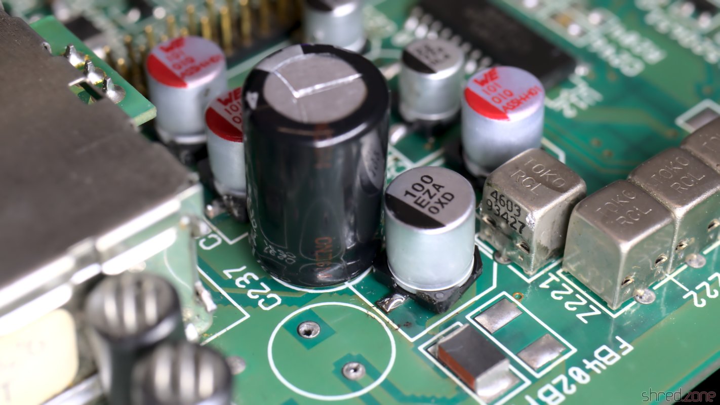
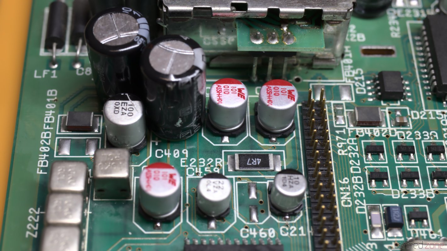
I recapped the mainboard and piggyback board. For the seven 22µF capacitors, I used a bipolar type instead. Those capacitors are used for filtering the audio and RGB signals. Using bipolar caps here might improve the signal quality, and won't hurt otherwise.

To be honest, this time I had doubt if I should replace the old capacitors. This Amiga 1000 will not become a workstation, I have other Amigas for that. It is rather a collectible. Still I want it to be in a good technical condition. When I started to collect retro computers, I promised myself not to keep machines that are broken or otherwise not fit for use.

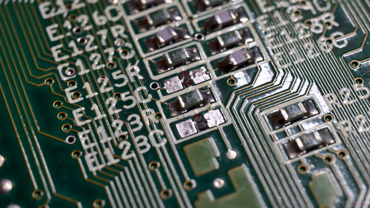
After that I removed all the dust, and gave the boards a thorough wash with IPA.

The mainboard, with fresh electrolytic capacitors.

The mainboard is now ready to get remarried with the piggyback board, and then move back into the case.
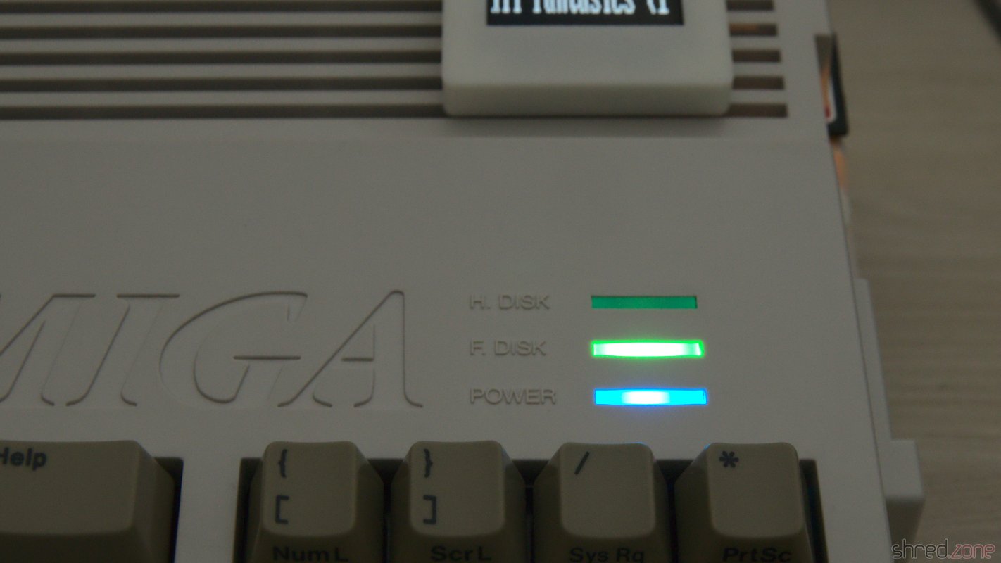
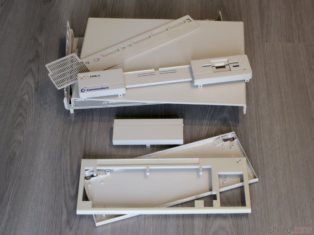
Whitening

The first thing I actually did was to disassemble the entire machine. The plastic parts of the case were cleaned in soap water and carefully scrubbed with a dishwashing brush. After that, I used the sunny July weather, and whitened all parts in the sunshine. I did not use any chemicals, just the sun. After two days, the Amiga was almost white again.

All case parts are whitened and ready for reassembly.

That's it for the first part of the Amiga 1000 story. The next part will be about the restauration of the keyboard. There is a lot to do there.

MaestroPro Internal

MacroSystem Maestro Professional In the mid 1990s, MacroSystem Germany released the Maestro Professional sound card for the Amiga. It was a special sound card because it was fully digital, having only optical and coaxial digital connectors. It was suited for lossless recording from CD and DAT, as well as generating lossless audio output for DAT recordings. With tools like Samplitude, the Amiga became a studio quality digital audio workstation. There was also a tool for doing backups on DAT. At that time, these tapes were the cheapest way to backup entire harddisks (a 90 minutes DAT tape could backup almost 1 GB of data, which was a lot in the 1990s).

Unfortunately MacroSystem had never released a driver for the sound card, so it could only be used by a few (and mostly commerical) tools. I pestered their developers at every Amiga fair I could attend, but to no avail. Then, at the end of 1994, I decided to find the datasheets of the Yamaha chips, reverse engineer the board design, and write a driver myself. It took some time of trial and error, but eventually I was successful. In the coming years, my driver, the maestix.library (source code), became the inofficial standard driver. OctaMed Professional is maybe the most prominent software using it. Some professional music artists used Amiga and OctaMED for their production, so maybe my driver was even used for recording the masters of some famous CDs? 😁

Digital Audio in a Nutshell

The MaestroPro is able to receive and transmit digital audio data, either in the S/P-DIF or AES-EBU standard. The former one is still widely used in home equipment today, while the latter one was rather common in studio equipment. Today's standards permit different encodings and high sampling rates, but the MaestroPro could only read 2-channel 16-bit raw audio with sampling rates of either 48kHz (DAT), 44.1kHz (CD), or 32kHz (DAB).

Besides the raw audio data, the standard also transports Channel Status Bits (CSB) and User Data Bits (UDB). The CSB contain information like the used sampling rate and the copy prohibition state. The UDB are not standardized, and usually transport proprietary data between studio equipment.

Inside the Maestro

The board's design is straightforward. It mainly contains a transmitter, a receiver, and FIFO memory for transporting the samples between the board and AmigaOS.

Receiver
YM3623B DIR
Receiver...
Transmitter
YM3437C DIT2
Transmitter...
Serial to Parallel
Serial to Parallel
Parallel to Serial
Parallel to Serial
R-FIFO 1Kx16
R-FIFO 1Kx16
T-FIFO 1Kx16
T-FIFO 1Kx16
DATA BUS
DATA BUS
Board
Controller
Board...
UDB Shift Register
UDB Shift Register
Sampling Clock
Sampling Clock
48kHz
48kHz
Optical
Optical
Coax
Coax
Optical Out
Optical Out
Input Signal
Input Signal
FIFO
FIFO
Bypass
Bypass
In
In
Source
Source
UDB Data
UDB Data
Text is not SVG - cannot display

The optical and coaxial inputs go to a Yamaha YM3623B Digital Audio Interface Receiver (DIR). This chip decodes the audio data stream, extracts the CSB and UDB, and generates a raw bit stream of the audio samples. Shift registers convert it to a 16 bit parallel stream, which is stored in a 1K x 16 bit receiver FIFO. As soon as the FIFO is half filled, an interrupt is raised, and the Amiga driver reads the received data from the FIFO. This happens up to 190 times per second.

The most important CSB are readable via a status register of the board controller. The UDB are copied to a separate 8 bit shift register, which could be polled by the driver. However, UDB are usually 32 bit wide, so reading them was never really used in practice (at least not to my knowledge). The Maestix driver only provided a very rudimentary API for the UDB.

On the transmitter side, the 16 bit samples are pushed to a transmitter FIFO, and then converted to a serial bit stream by shift registers. A Yamaha YM3437C Digital Audio Interface Transmitter (DIT2) converts it to a digital audio stream and sends it via an optical output. The Maestro Pro does not have a coaxial output, presumably because there was not enough space on the board for a fourth connector.

The DIT2 is unable to generate the sampling rate clock by itself. It needs an external clock source instead. On the Maestro Pro, this clock is generated by the DIR. It is either derived from the bit stream of the selected input, or generated by an internal fixed 48kHz clock source. For this reason, the Maestro Pro needs to rely on external signal sources for 32kHz and 44.1kHz output sampling rates.

The transmitter can choose from two data sources. One source is the transmitter FIFO. The other source is the bit stream from the DIR, bypassing the FIFOs. This enables the board to modify the UDB and CSB of the incoming signal directly, without involving the CPU. But since the transmitter and reciver paths are fully separate, the MaestroPro is even capable of providing full-duplex audio streaming. The maestix.library takes advantage of that with the "realtime FX" feature, where the signal is read from the receiver FIFO, modified by the CPU, and then immediately sent back to the transmitter FIFO.

The entire board is controlled by three GALs and a small handful of 74LS logic chips. They take care of the Zorro bus protocol, provide mode and state registers, and orchestrate the transmitter and receiver paths.

Broken MaestroPro

All of the components of a MaestroPro can still be found on the market, although both Yamaha chips are not produced any more and can only be found on some Chinese online markets as NOS parts. But basically, it is still possible to repair a broken MaestroPro.

The major weakness are the three custom programmed GALs. The GAL manufacturer states a memory retention time of about 20 years. It sounds like pretty much, but remember that these boards are almost 30 years old now. We already exceeded that life span by 50%!

When I reactivated my Amiga in 2021, my MaestroPro was working fine for a couple of minutes, but then it started to lose synchronization with the audio source. The only way to fix that problem was to turn off the Amiga and let it cool down for several minutes. A deeper diagnostics showed that the card seemed to detach itself from the Zorro bus. It seemed that one of the GAL chips had thermal problems, or was maybe starting to "forget" its programming. Fortunately I was able to recover the programming scheme. I replaced the original GALs with brand new Atmel ATF16V8C-7PU ones, and to my relief, my MaestroPro is now working stable again.

The fusemaps are copyrighted by MacroSystem, so I am not permitted to share them to the public. However, if you happen to have a broken Maestro Pro, please get in contact with me. Maybe I can help you to repair it.

The Maestro (without Pro)

There was a predecessor of this board. It was just called "Maestro", and had some major drawbacks. First of all, it had no transmitter and could only receive audio data. Secondly, it did not have a FIFO, so the sample words had to be read by the CPU as soon as they became available, which is up to 96,000 times per second. This was only possible by turning off multitasking and interrupts during recording, which also meant that recordings could not be written to harddisk, but had to be stored in RAM first.

Compared to its successor, the Maestro hasn't been a great success. I haven't seen one since the end of the 1990s, and I also don't know a single software that is actually using it. Due to the technical limitations, the Maestix driver won't support it.

Flash Amiga ROM

It's possible to use EPROMs to update your Amiga to the latest AmigaOS. Unfortunately these EPROMs are not produced any more, so it's becoming increasingly difficult to find these parts on the market. Another disadvantage is that a special UV light source is necessary to erase EPROMs, unlike modern Flash ROMs that can be erased electrically.

So wouldn't it be better to use Flash ROMs instead? Certainly yes, but they do not come in DIP-40 packages that fit the Amiga ROM sockets.

The Flash ROM Adapter

Soldering the Flash ROM chip on a hot plate. djbase kindly published the design of an Amiga Flash ROM Adapter. It can be equipped with 29F400, 29F800, or 29F160 Flash ROMs. They are available at all kind of electronic sellers, and can store up to four Amiga ROMs in a single chip.

Besides the PCB and the Flash ROM chip, you only need four SMD resistors, one SMD capacitor, and pin headers. The problem, however, is that the components are tiny, and the pitch of the Flash ROM chip pins is very fine, so this project is definitely not suited for soldering novices. Trust me. I made three of them for the bin before I was successful.

The Programming Hardware

The Hardware Sandwich For programming, I use an XGecu TL866II Plus programmer and the SN001 Adapter Kit. djbase also provides a special programming adapter, which is connected to the TSOP48/SOP44 base board of the SN001 adapter kit.

This programming adapter sandwich is put into the ZIF socket of the TL866 programmer. The Flash ROM adapter is placed into the ZIF socket of the adapter board, and the pin headers of both boards are connected according to their labels. Note that the current revision of the adapters support Flash ROMs up to the 29F160, and require five wires. I still use the previous revision with only four wires, because I like it better.

If you don't intend to change the Flash ROM content after soldering, you can also save the programming adapter and use the SN003 adapter instead (which often comes bundled with the SN001 adapter kit). You would then flash the Flash ROM before soldering.

The Binary File

For preparing the binary file, I use my Pynaroma toolkit. It takes care for joining multiple ROM files and the necessary byte swapping. For example, to create a ROM image of AmigaOS 2.04 and AmigaOS 3.2.1 for the Amiga 500, this command line can be used:

rom2bin -o flash.bin A500.37.175.rom CDTVA500A600A2000.47.102.rom 

Depending on the flash ROM chip, you can use up to four different ROM files of 512KB each. If the ROM file has a size of 256KB, remember to duplicate it.

Once the adapter is in the Amiga, the desired ROM image can be selected via the header address lines (e.g. by using jumpers or switches). Note that the address pins of the Flash ROM are pulled-up by the adapter. This means that the last ROM file of the sequence is used when all header pins are open.

Flashing

For programming, I prefer to use the open-source minipro software over the original software by XGecu, mainly because the original software is not available for Linux.

It is important to select the correct Flash ROM type. Pick the type that you have actually soldered to your adapter. Always choose the TSOP48 package, as the programming adapter simulates a TSOP48 socket.

I use a M29F800FT, so the correct device setting is M29F800FT@TSOP48, and the command line for flashing the binary file from above is:

minipro --device 'M29F800FT@TSOP48' --write flash.bin 

The Flash ROM will be erased (so there is no need to erase it before), the image written to it, and then verified in a final step.

ROM Replacement

Amiga Flash ROM adapter in an Amiga 500 The Flash ROM is a drop-in replacement for the Amiga ROM. I carefully removed the original ROM from the socket by using a screwdriver with a wide blade.

After that, I put the Flash ROM adapter into the socket. The correct orientation is crucial. The adapter is put with the header having the same orientation as the notch of the original ROM.

Sometimes the holes of the socket are too small to receive the pins of the adapter. In this case the only chance is to either replace the socket, or use an EPROM.

If you own an Amiga 500 Rev. 5 mainboard and experience random crashes with the new Flash ROM, you might need to add resistors to the address lines. This can be done either via resistor packs or by using an Amiga 500 EPROM adapter that is sold at some Amiga shops.

#Advertisement? This blog is free of ads. All shown products have been paid by myself.
Saturday, March 5, 2022
Action Replay

I got this Action Replay MK-I module. According to the seller it was untested, and for that reason sold as defective. It was in a… let's say very used state. The case was dirty, to a point that it was almost revolting to touch it. A side of the case was cracked open, and a knob was missing. The module must have been dropped at some time.

The Action Replay, in the sad state that I got it.

I carefully opened the case. The top and bottom shells are just stuck together, there are no screws, so it was easy to pull them apart. Inside I found some kind of coating on the PCB, so perhaps a drink had been spilled on the module as well. I also found a lot of fine paper dust like from a cardboard, and a small dent at the corner of the PCB that was caused by the drop.

Even the inside is filthy.

The first thing I did was to give the entire module a proper cleaning in an ultrasonic cleaner, just with warm water and a drop of dishwasher detergent. And yes, I also washed the PCB that way, then dried it off and sprayed it with IPA to remove the last traces of water. That bath did wonders.

Before cleaning: Dirt everywhere, and also this strange matte coating on the PCB. After cleaning, the board looks almost as new. I removed a few parts before the bath.

I expected that the dirt also reached the inside of the mechanical parts, so I decided to replace them all. They were a bit hard to find as replacement parts, but still available. As the original knob was lost, I used a different potentiometer that came with a knob. Unfortunately the new one is white, while the original one has likely been black, so I couldn't fully restore the original outside look.

New electrolytic condensors and mechanical parts for the rejuvenating cure.

The case was cracked open at one side because two pins inside were broken off. I fixed the pins with superglue. After that I exposed the case to the sun for a day, which removed quite a bit of the yellowing. Then I could put everything together again. Compared to the original state, the Action Replay is now looking nice and clean.

The Action Replay, shiny and as good as new.

I gave it a test run in my Amiga 500, and it was working fine! Now I have an Action Replay for my Amiga collection. The only sad thing is that it cannot be upgraded to an MK-II or MK-III, as these modules are constructed differently.

Amiga 1200 Restauration

Ever since I got my Amiga 4000, I was pondering about if an Amiga 1200 would have been a better choice. I mean, the Amiga 4000 is nice because it has a lot of space for extensions. But on the other hand, it is rather bulky and heavy, so it isn't much fun to take it to a friend or a party, unlike the compact and light Amiga 1200.

But why not have both? 😉 I had found an Amiga 1200 offer on the Bay that was too good to be ignored, so I bought it.

My new Amiga 1200, unboxed. The keys are yellowed, and the Amiga badge is just a cheap sticker.

It's an Amiga 1200 from the days after Commodore went belly up, and when Escom took over and sold the last Amiga stocks. The good news is that the Escom cases were made of ABS with an anti-UV treatment, so they will never yellow. The bad news is that the keycaps were not treated, and are very visible yellowed by now.

I sent the keycaps to the experts at the CBM Museum Wuppertal for whitening. The case itself is almost in a mint condition, all it needed was a bath in warm dishwater.

Let's take the computer apart and have a look inside.

After opening the cover and removing the keyboard.

There's a 2.5" hard disk, which turned out to contain a Workbench, a few games, and also many bad sectors. I'm going to replace it with an SD Card solution anyway. The shielding has a bit of flash rust and was bent around the ROMs, probably from forceful prying out the ROM chips with a screwdriver. Besides that, the overall status is quite okay.

The mainboard is in a good condition. I've already changed the Kickstart ROMs.

Under the shielding, I found the mainboard in a good condition, especially without flash rust on the modulator. To my surprise, it is a Rev. 1D.1 board, which was actually the first broadly sold board revision. In one of the last Amigas that have ever been produced, I had rather expected to find a revision 2 board. Anyway I was lucky because the 1D.1 revision is said to be the most stable one, and it also has a good Lisa chip that was manfactured by HP. On both CIA chips I found traces of flux, so the board seems to have been repaired before.

It's a rather early Rev 1D.1 board. I didn't expect to find that in one of the last Amigas ever sold. It also seems that this board has been repaired before.

According to my contact at the CBM Museum Wuppertal, Escom sold everything they could find at the Commodore remainders. Allegedly they also produced "new" Amiga computers with refurbished mainboards. Maybe this is one of them?

I first inserted diag ROMs and checked the hardware, but found no problems, so I upgraded the system to AmigaOS 3.2. The next thing on my to-do list was to replace the electrolytic capacitors, as they tend to leak over all those years, causing damage to the PCB. I have already done that on my Amiga 4000 before, but on this model the space was a bit more limited. I even had to remove a freshly replaced SMD capacitor because another capacitor did not fit next to it any more.

Two capacitors are overlapping. It's a tight space. Eventually I replaced all electrolytic capacitors.

To enhance the stability of accelerator boards, it is recommended to remove the capacitors E123C and E125C on the bottom side of the PCB. The easiest way is to use two soldering irons like a pair of tweezers.

The bottom side, with E123C and E125C removed.

After a thorough wash with IPA, the board was then ready to move back into the case.

The board after recapping, ready to move in again.

I want to modernize the Amiga so it can be connected to a HDMI monitor. The RGB to HDMI solution of the Amiga 500 won't work on the AGA chipset though, so I decided to get an Indivision AGA MK3 from Individual Computers. It is plugged onto Lisa and one of the CIA chips, and offers an HDMI output even with sound. (Which is quite an accomplishment, as both chips are not connected to a sound line.)

Since I was on it, I also extended the memory with an ACA1211. Unfortunately it turned out that AmigaOS 3.2 is incompatible to the ACA1211, and the system won't boot in this combination. I had to return to the original AmigaOS 3.0 ROMs again. Eventually I traded the ACA1211 for an ACA1234, which is also an accelerator and works fine with the latest AmigaOS.

To make the wire mess complete, I replaced the floppy disk drive with a GOEX drive from Centurion Tech.

The Indivision AGA MK3 and the ACA1211 mounted. The GOEX floppy simulator replaces the original floppy disk drive.

Centurion also offers LED boards with customized colors. I have picked blue as power LED, green as floppy drive LED, and red as harddisk LED.

New LEDs in my favorite colors! 😍

In the meantime, I got the whitened keycaps back. They were almost white again, but sadly there is still a slight, but visible yellow tint. Maybe I will buy a new set of key caps once they are available. The Amiga would then look as new.

The original Escom label is just a cheap sticker. It looks ugly to me, so I replaced it with a replica Commodore badge.

And then, for the first time after my purchase, I could close the Amiga 1200 case again.

This is my refurbished Amiga 1200/030.

Please welcome the newest addition to my Amiga collection!