Peace Memorial Park, Hiroshima

#Amiga

Amiga 4000 Restauration, Part 1

A few years after I got my Amiga 500, I bought an Amiga 4000 from the pay I got doing my civilian service. At its peak, it was housed in an RBM Big Tower case, and had all kind of expansion cards and an 68060 accelerator board. It was my pride and joy. Later, after Commodore went bankrupt, I switched to Linux systems. My Amiga 4000 was put on a diet and moved back into a desktop case.

The restored Amiga 500 is meant to be used for playing old games and watching demos. In contrast to that, the Amiga 4000 is supposed to become a workstation again. It should be connectable to modern monitors, and should be as silent as possible.

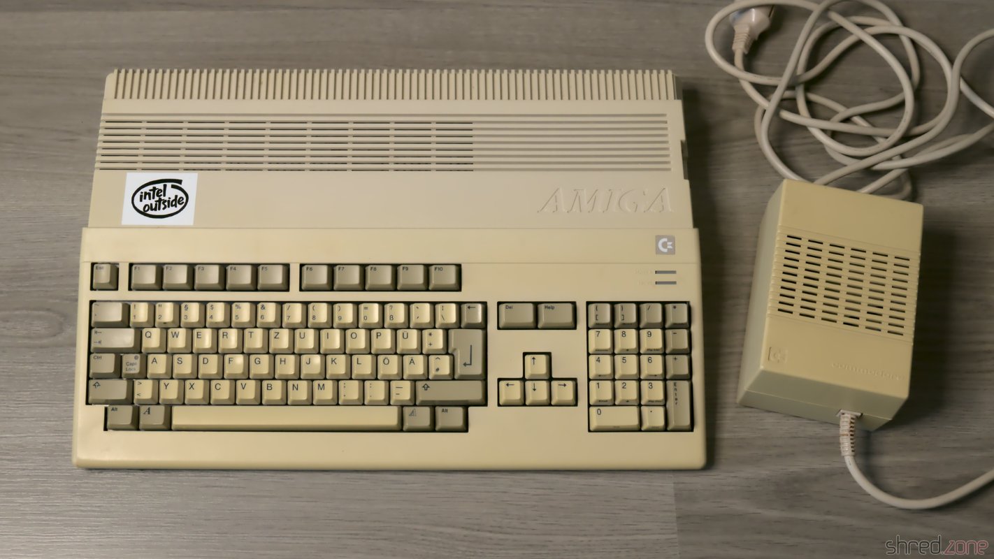
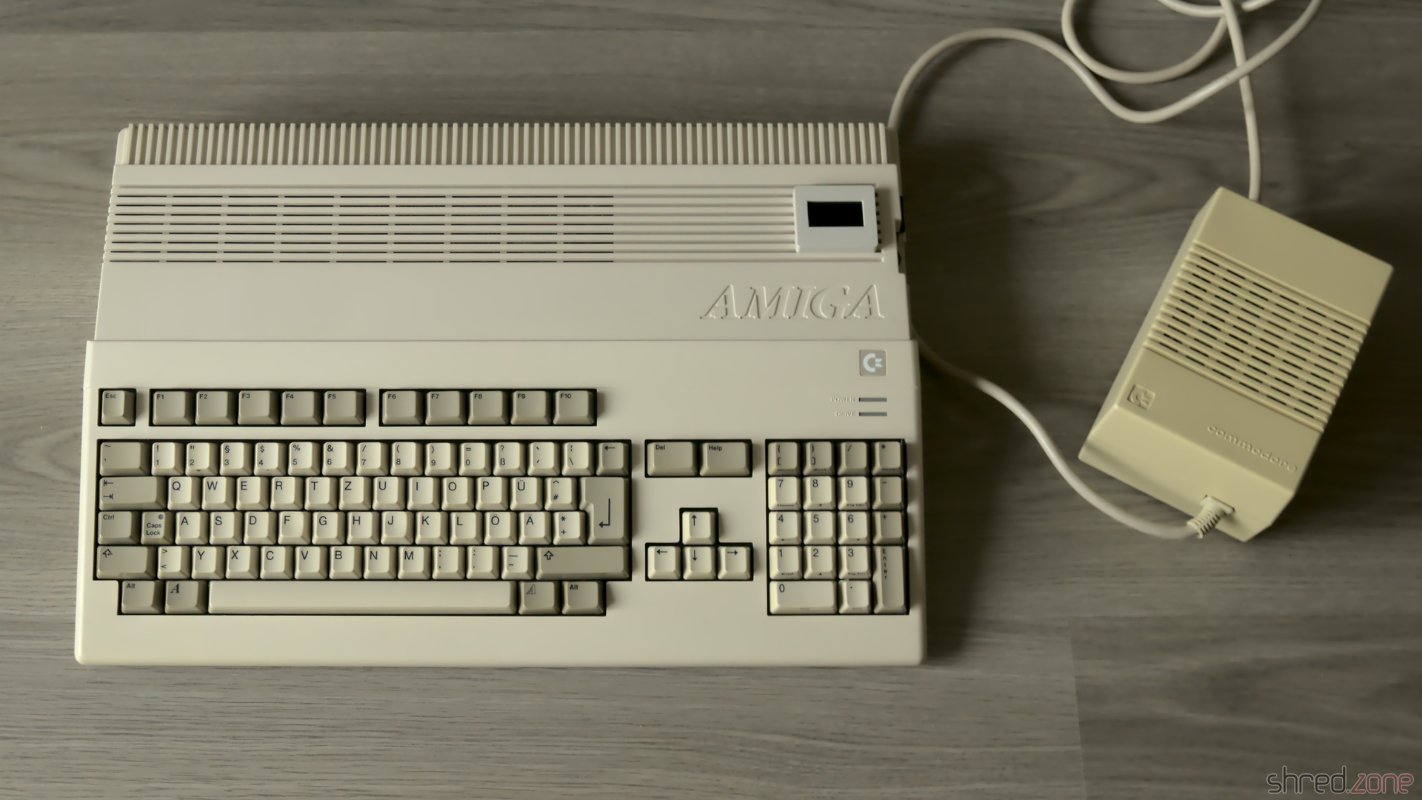
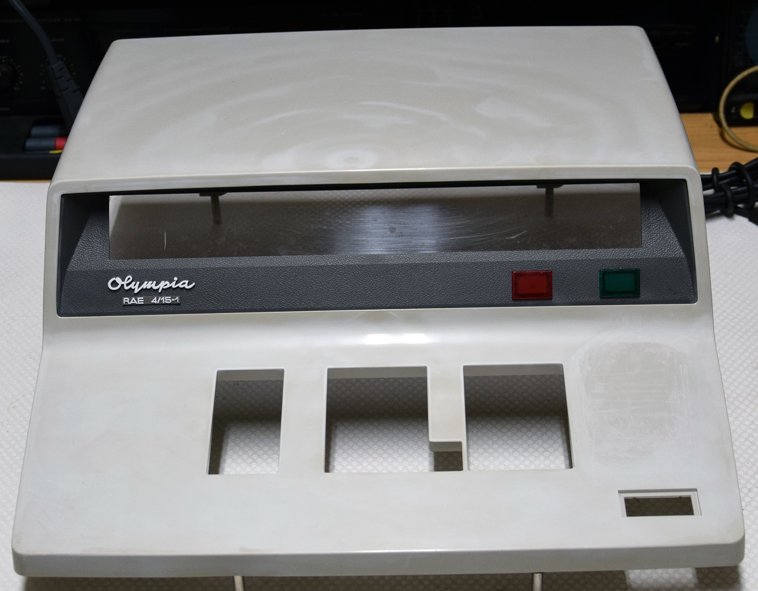
This is the state of the case before restauration.

The "before" photo. The front panel has clearly suffered in the past 30 years.

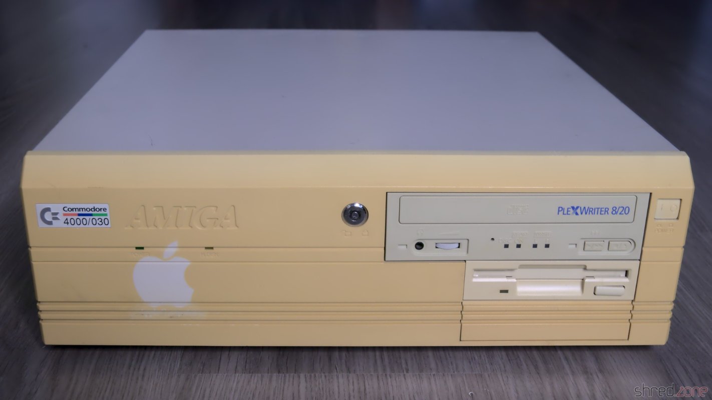
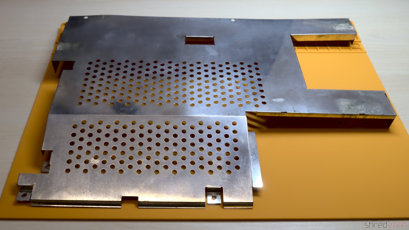
The computer has suffered a lot in the past decades. The powder coating of the metal cover got a lot of deep scratches from CRT monitors that were placed on it. The plastic front got a deeply yellowed tint. To make things worse, there was a sticker on the front that kept the plastic from yellowing, but now the outline is permanently "burned" into the front instead. The keyboard was in a similar state, although not that badly yellowed.

The CBM Museum Wuppertal already did an excellent job with whitening my Amiga 500, so I decided to also let them whiten the front panel and the keyboard. The experts at the museum warned me that the logo might stay visible after whitening though, but then I could still resort into dying the front black, or even 3D print a new front.

Meanwhile a paint shop is taking care for repainting the metal cover. I decided to keep the original color, RAL 7044 (silk grey).

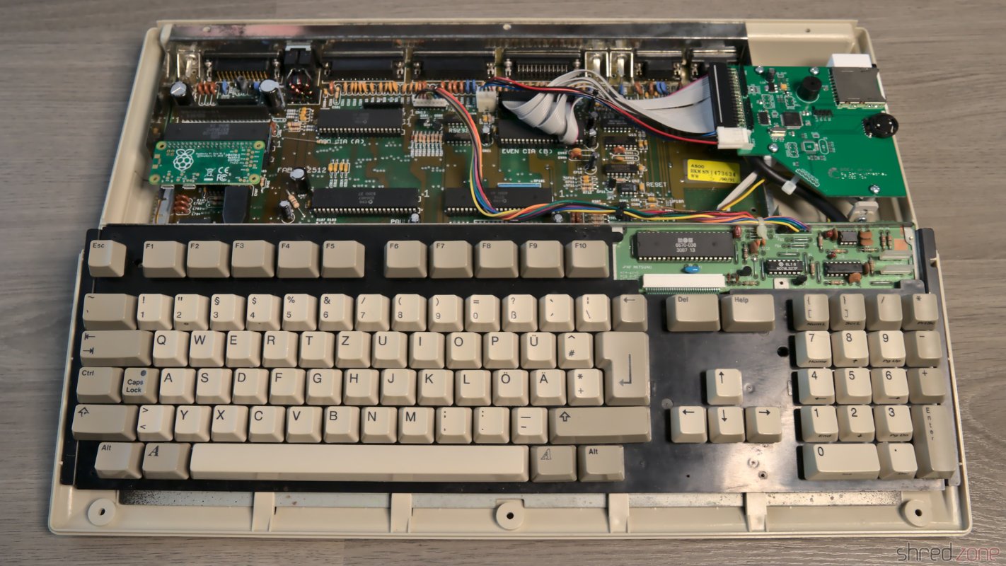
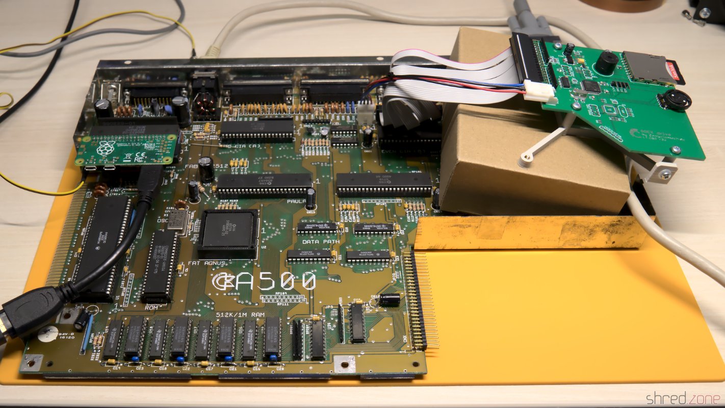
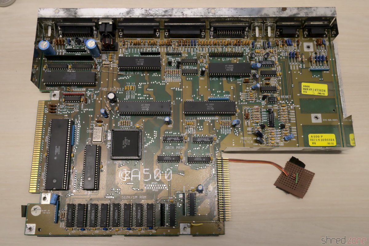
Let's have a look at the inside now.
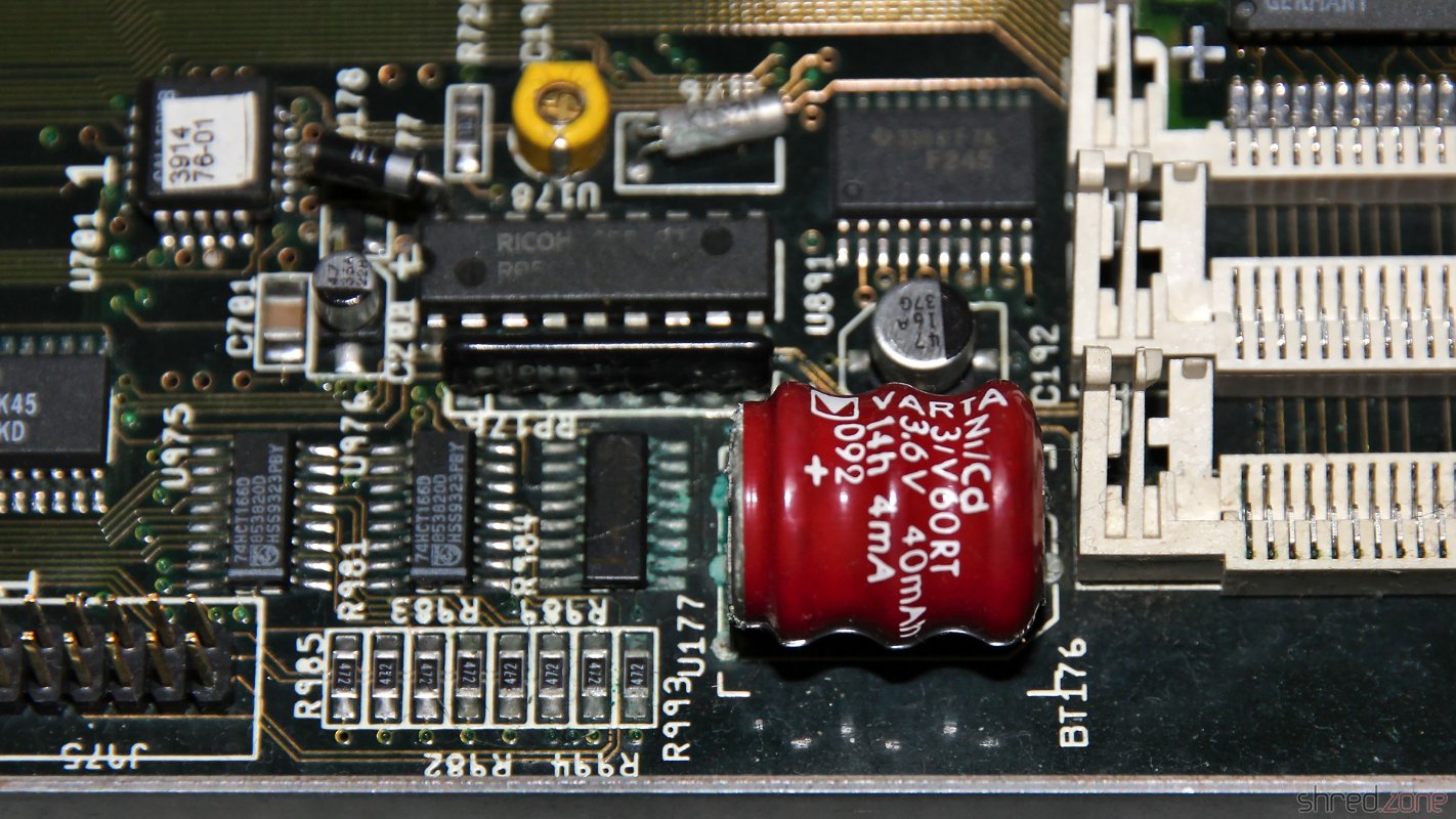
Leaked Battery

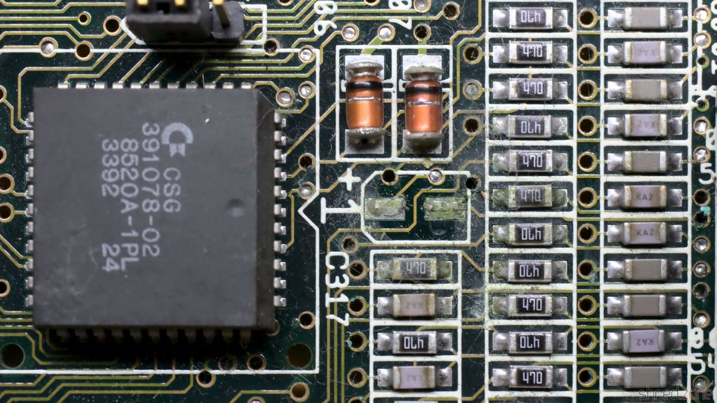
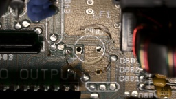
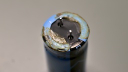
A true Amiga killer is the NiCd battery that serves as a power backup for the RTC. Sooner or later it leaks and spills battery lye onto the PCB. The lye corrodes the components and traces in its vicinity. If untreated, the board can become irreparably damaged over time. When I first heard about the problem eight years ago, I immediately cut out the battery, but sadly it had already leaked.

The leaked battery, before removal.

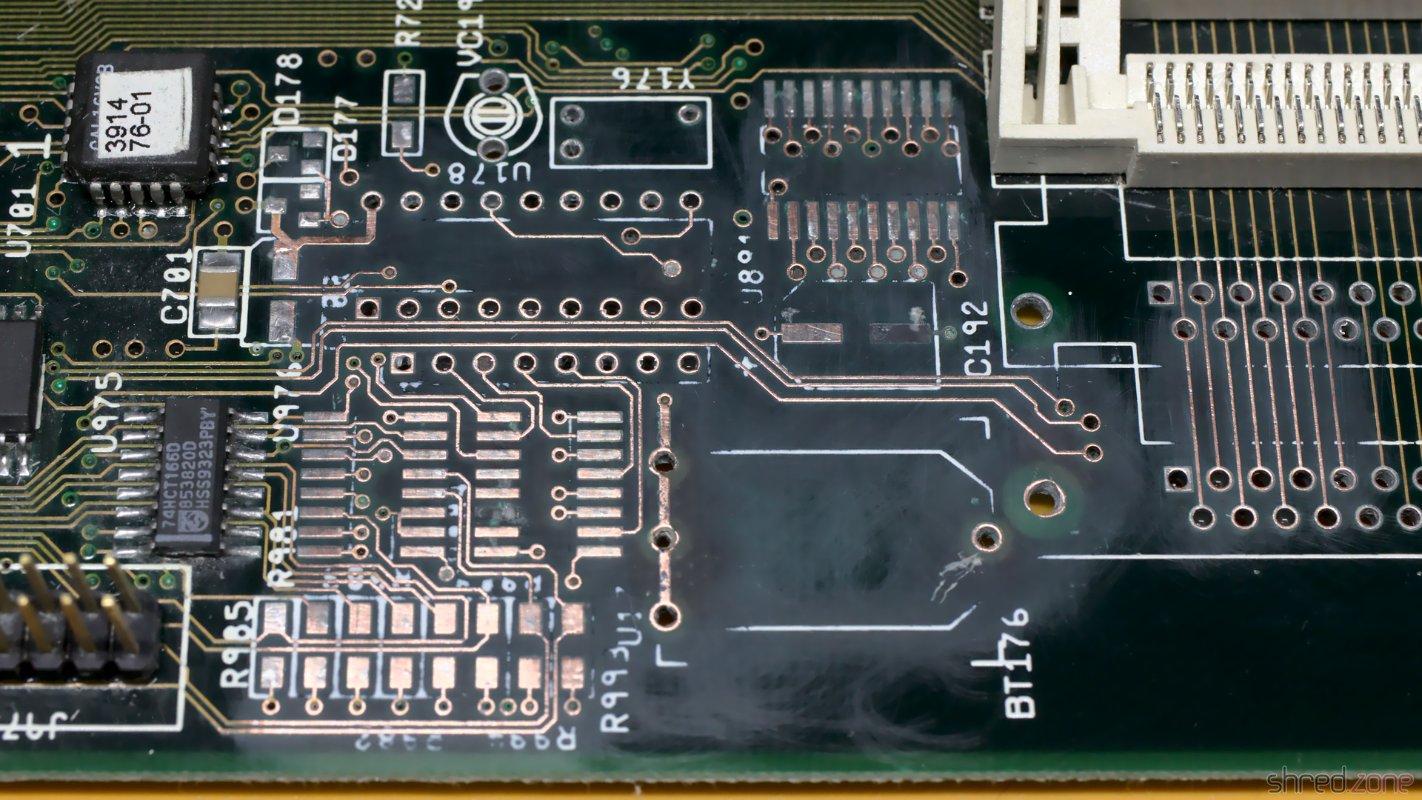
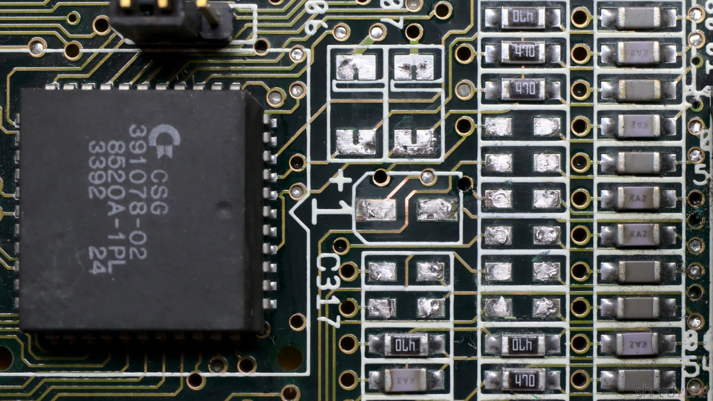
For the restauration, I needed to repair this part of the PCB. I generously removed all affected components. Then I neutralized the lye with vinegar essence, rinsed the area with water, then cleaned and dried it with IPA. After that, I used a fiberglass pen to remove the solder mask down to the bare copper, to have an unobstructed look at the damage.

I lost two pads that seemed to be too damaged by the lye. They just came off while I was cleaning the board. Luckily one of them was not connected, and the other one could be replaced with a short piece of wire.

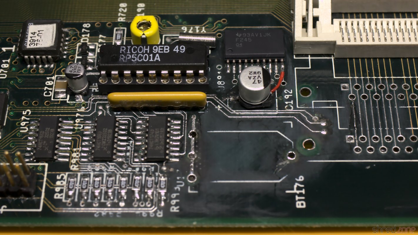
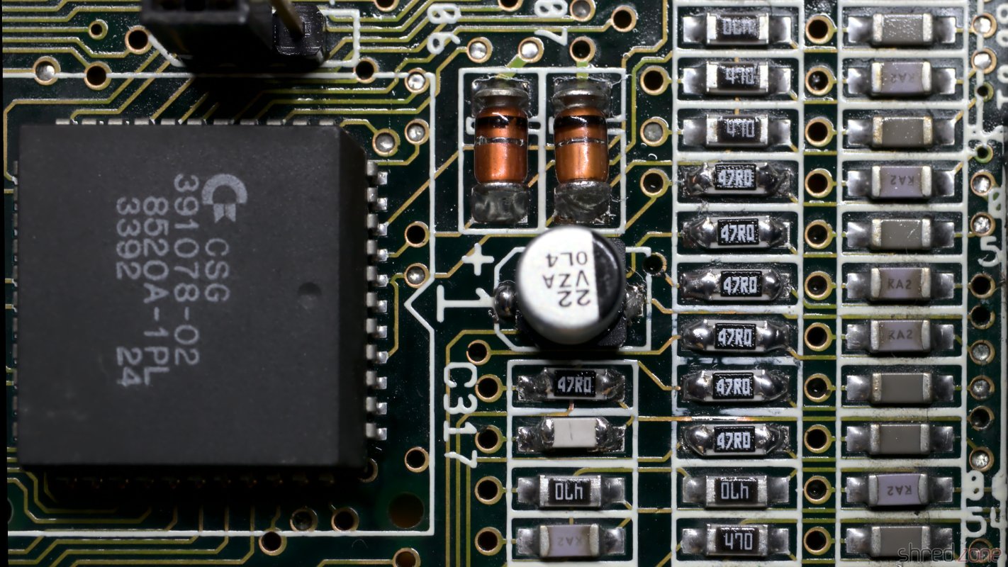
After that I rang all the traces. Three of them were open and also needed to be fixed with a piece of wire. I then used solder to tin the bare copper traces and protect them from corrosion. Finally, I soldered in fresh components.

All affected parts generously removed, and the PCB scrubbed down to the bare copper.The bare copper was tinned to protect it from corrosion. I also had to fix some open traces.Fresh components soldered in. One lost pad was fixed by a wire.

The lye may run to the bottom side through the vias, so it should be checked as well, and repaired if necessary. Luckily I could see no damage on my board.

Since the old rechargeable battery almost killed my Amiga, I decided to use a 3V button cell for backing up the RTC. To prevent the cell from being charged when the power is turned on, I replaced R179 with a standard diode.

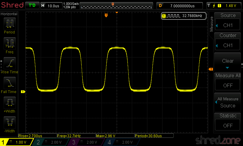
Since I removed the crystal and capacitors, the RTC needs a recalibration. I connected pin 17 of the RTC chip (U178) to a scope, and then used a plastic screwdriver to adjust VC190 until the measured frequency was exactly 32768 Hz.

Recapping

Electrolytic capacitors may leak, similar to the battery, and it is recommended to replace all of them with modern premium caps. Some people replace them with ceramic capacitors. They cannot leak, but may have other disadvantages. There are good arguments on both sides, so it's a decision that everyone has to make themself. I decided to order the premium capacitors from my Amiga 4000D Bill of Material list. They are made by Panasonic and have an expected lifetime of up to 10,000 hours, which is maybe the tenfold of the original caps. They are also certified for temperatures of up to 105°C, which further extends lifetime.

There are different ways to remove the old electrolytic capacitors. The recommended way is to use two soldering irons, or a hot air rework station. I decided to use a different method that I read about, and twist them off with pincers. It worked surprisingly well, and it took only a few minutes to remove all the caps. To avoid causing damage to the pads, care must be taken that the caps are only slowly twisted, but not pulled from the board.

On the Amiga 4000 the leakage usually starts in the "audio corner", where many SMD caps are concentrated on a small space. I was lucky because all the caps were still intact there. On my board, C317 has leaked though. It was visible by the corroded solder joints around it. When they were heated, there was also a typical telltale smell of microwaved fish. Again, I generously removed the components around the damaged part, cleaned the PCB, and soldered in new parts.

C317 has leaked and corroded the surrounding.All affected parts removed, and the PCB cleaned up.New parts soldered in, with a bit too much solder though. 😅

There are also a few axial caps on the daughterboard. They usually don't tend to leak as easy as SMD caps, but since we're on it, they should be replaced as well.

When I repared the battery damage, I also had to remove two of the SIMM sockets. The original sockets have plastic brackets that easily snap off, so I decided to finish what I started, and replaced all five sockets with new ones having metal brackets.

In a final step, I washed the board with IPA. It was then repaired, cleaned, and ready to be put back into the computer case.

The restaured mainboard. It won't win a beauty contest any more, but I hope it is working again.

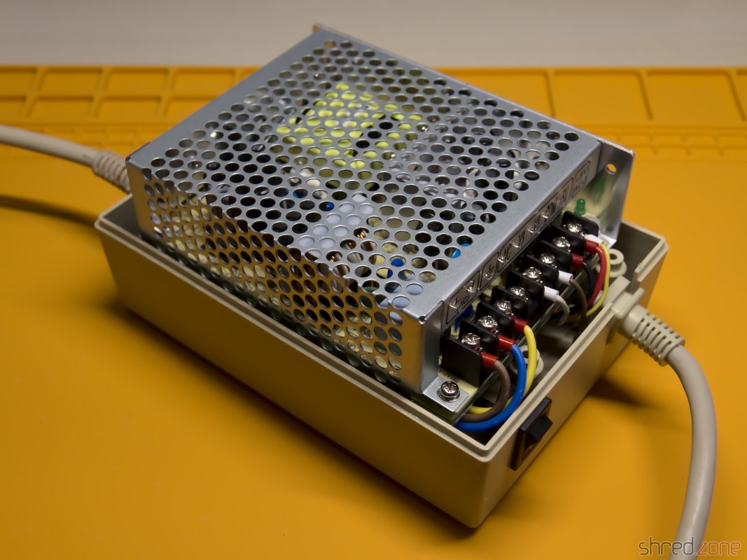
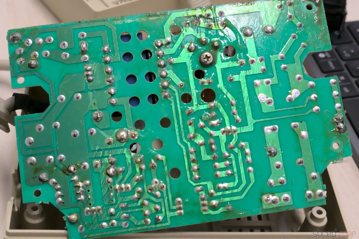
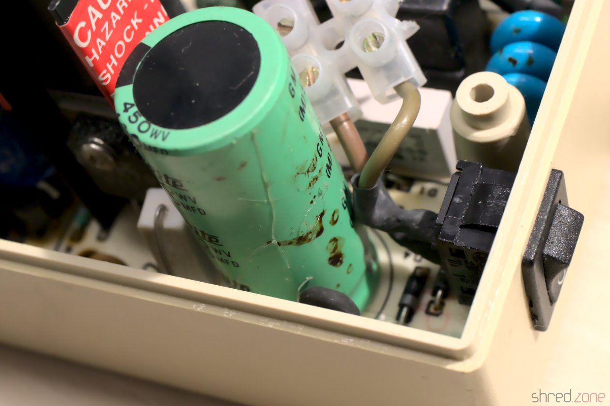
In the next part I will take care of the power supply, and I will put the system back together.

Amiga 500 Restauration, Part 3

After the test run was successful in the previous part, it's now time to put my Amiga back together.

Whitening

I've got the case parts and keycaps back from whitening at the CBM Museum Wuppertal. And the mandatory before-after photos proove that they did a great job:

Before whiteningAfter whitening

Sadly the PSU case is made of a cheaper material, and could not be whitened any further without risking the dreadened "marbling", so it stills look a bit yellowed. (I forgot to use a ring light for the photos, but I did my best to make both pictures comparable.)

Removing the Rust

Due to my careless storage in the cellar, the metal shielding got a bit of rust over the years. I removed the worst rust spots with a fiberglass pen. Then I polished the shields with Nevr-Dull wadding polish, which removed a lot of the rust film. The result is still far from perfect, but it's hard to impossible to restore the original look of the shielding, so I decided to keep it that way.

The upper shield after removing the rust and polishing.

PSU

I have already prepared the PSU in in the last part. Now that I also got the PSU case back, it's time to put it together. I've first replaced the power switch, as the old one got broken over the years. Luckily it's a standard switch that can still be found at electronic shops.

The RT-65B in its new housing. The photo shows an early attempt with swapped mains and power cables.

The Mean Well RT-65B fits into the case surprisingly well, almost as if it was made for it. I only had some difficulties to find a proper position for the wires. I tried different positions, and also tried to switch the sides of the mains and Amiga power cables.

The best result seems to be the original orientation of the cables (mains cable at the side of the power switch). With a bit of tweaking, I could finally route all the wires properly, make the RT-65B fit in, and close the PSU case.

I recommend to check the correct wiring (especially of the earthing) and the voltages once again. Also make sure that the terminals are firmly closed, and that no wires are overly bent, squeezed, or punctured.

GOEX Drive

The GOEX drive optionally comes with an OLED display that sits on top of the Amiga case and shows the currently selected file, and the current disk track. I can really recommend to order that display with the drive, as it makes selecting a file a lot easier. Unless of course you use the "GOEX on pills" version that offers a disk menu on the screen as OSD, but I wasn't sure how this version would interfere with the RGB-to-HDMI converter I am using.

The display is readily assembled, and already has crimp connectors at the end of the cable. The idea was to push them through an opening of the ventilation grille, but they just were too big for that. I had to cut them off, push the ribbon cable through an opening, and then solder new connectors to the cable.

HDMI Connector

Next problem was the HDMI connector. I use c0pperdragon's RGB-to-HDMI converter to connect my Amiga to a TV or monitor via HDMI. But where should I put the HDMI connector so I can reach it from the outside of the case?

My original idea was to cut a matching hole into the back of the Amiga case, but later I dismissed the plan and decided against disfiguring the case even further than I already did in the 1990s. A better idea was to print an expansion port cover with a hole for a HDMI cable, even though I disliked the thought that a cable would then loosely hang out of the case.

Then I noticed that the GOEX drive left a hole where the floppy drive's eject button has once been. And this hole is actually big enough for a HDMI connector, almost as if it has always been meant for that purpose.

The HDMI connector fits amazingly well!The holder frame (white) sits within the frame of the GOEX drive (grey) and does not need any screws.

I designed a 3D printed frame that holds the connector of a Delock 85463 panel-mount HDMI connector. You can find the STL file at Printables for reprinting.

It looks a bit weird when a HDMI cable is plugged into that place where once the disk eject button has been, but it is working amazingly well, and saved me from cutting further holes into the Amiga case.

Completed

Now everything was mounted in its place. I couldn't close the upper shielding though, because the HDMI converter is in the way, so I decided to leave it out.

Everything is completed and in its final place.

And that concludes the restauration project. Welcome back, Amiga 500. With this hardware upgrade, you should be fit for at least the next decade.

Welcome back, Amiga!

The Kickstart Dilemma

Well, not quite. There is a Kickstart 2.04 ROM installed in this Amiga, and while playing some old games, I found out that a surprisingly large number of them crash on that version of the AmigaOS. It was indeed a big problem of the Amiga back in these days. In the previous generation of home computers, the operating system was static and was never updated, so programmers assumed to find certain routines at fixed positions. When the Amiga got popular, programmers continued to use the operating system like that, ignoring documented rules. Then in 1990, Commodore released Kickstart 2.0, a major AmigaOS upgrade. And suddenly, many poorly programmed games crashed, but instead of the programmers, the Amiga was blamed for it.

I still have an original Kickstart 1.3 ROM here, along with a ROM switch. Maybe I will use that board again. Luckily, I haven't yet closed the holes that I once drilled into the case, so I can use one for the switch again.

Amiga 500 Restauration, Part 2

In the first part, I dusted off and checked my old Amiga 500. I've also ordered all parts for the project, and they have been delivered by now. Let's start with the restauration!

Recapping

All home computers of the 1980s and 1990s have been designed for common households, and thus had to be cheap. Commodore did not expect that the Amiga would become an "old dame" some day, so they used standard components. A common problem is that electrolyic capacitors dry out over the years, losing their capacity. Some may even leak and, in worst case, damage the board. So the first restauration step is always to replace all electrolytic capacitors, even if they should still look fine.

As I don't want to repeat that process in a decade or so, I ordered premium capacitors with an expected lifetime of 10,000 h, which is probably tenfold of the standard caps' lifetime. At the bottom of this article, I have listed all the caps on my Amiga 500 Rev 6A board.

On the first sight, all capacitors seemed to be fine. Still, after removing one of them, I found traces of dried electrolyte on the board and at the bottom of the component. It really shows that a superficial inspection can be deceiving.

I also removed the wires of my self-made NMI button, and looked for cold solder joints and other potential problems. As final step, I carefully washed the mainboard with IPA.

Recapping completed!

HDMI Output

Let's start with the next construction site. As it gets more and more difficult to find TVs with a SCART connector (and I never liked them anyway), I want to connect my Amiga 500 via HDMI. Luckily there is a project by c0pperdragon that adds a pixel-perfect HDMI output to the Denise chip. The converter cannot be bought at shops, but you need to assemble it yourself. It consists of a few standard components that can be bought at good electronic shops, while the board can be ordered at PCB manufacturers. The assembly requires some fine-pitch SMD soldering though. If you don't feel comfortable with that, you maybe find a private seller for a readily assembled board.

To install the adapter, the Denise chip is removed from its socket first. Then the adapter is placed into the socket, and Denise into the adapter. A button can be connected for changing the configuration and taking screenshots, but that is not really required for operation.

The RGB to HDMI adapter. Denise is already plugged in, but the Raspberry Pi Zero is missing.

The RGBtoHDMI firmware needs to be extracted to a FAT formatted MicroSD card. Make sure to use release 20210322_f771e51 or later. Earlier releases will not work, but only show four colored rectangles.

Finally the Raspberry Pi Zero is plugged into the socket. Be very careful here! The pin header will also fit if not aligned properly, and may then damage your Raspberry or (even worse!) your Amiga.

It's easy to make a mistake here, so be extra careful that the Raspberry is properly connected.

New Power Supply

In the first part I found some liquid at the bottom of the power supply's PCB. I suspected it was capacitor liquid, but my contact at the CBM Museum Wuppertal explained me that it was just a lot of flux. Still, the old power supply would need a technical overhaul, which I can only recommend to people who know exactly what they are doing.

WARNING: Switched power supplies may still contain high voltages hours after they have been disconnected from mains. I strongly advise against attempting repairs yourself. If you decide to keep your old PSU, please ask a trained technician to restore it for you!

As I am not "trained personnel" myself, I decided against restoring the original PSU, but for replacing it by a Mean Well RT-65B. It has sufficient power, and also fits nicely into the original Amiga PSU case.

Before I removed the wires from the old PSU, I took notes on what color is connected to what voltage. Then I removed the wires, put crimp shoes on the wire endings, and connected them to the corresponding output of the new PSU.

My original PSU had a separate SEN wire. It is connected to +5V at the power plug, and is used so the old PSU could compensate wire losses and provide exactly 5V there. The replacement PSU does not provide a sense connector, so I just connected the SEN wire to the +5V line to increase the total cross-section and reduce losses, but it can also just be left open.

The "shield" wire must be connected to earth.

ATTENTION: There were different variants of Amiga 500 power supplies on the market. Your number of wires, and the wire color code, may be different. Do not just rely on my photos!

This is how it looked like after the wiring:

Mains power below, Amiga power above. Shield is connected to earth.red: +5V – black: ground – brown: +12V – white: -12V – yellow: +5V sense. Your colors may be different!Amiga 500 power connector pinout.

Do not connect your PSU to mains yet! First switch your multimeter to continuity test mode, and test if your earthing is connected to the PSU case, and to the shield and the shield pin of the Amiga power plug. After that, test if the power lines are properly connected. Now you can power up your PSU, and use your multimeter to check the voltages at the Amiga power plug.

ATTENTION: Please be very careful when you test the PSU outside the case. Make sure you cannot accidentally touch the live terminals. Also do not open the shielding of the PSU.

Test Run

After I made sure all voltages are correct, it was finally time for a first test run.

As I don't have many disks any more, I had ordered a GOEX drive as a replacement for the original floppy drive. It emulates a disk drive, but uses ADF files from a SD card. It even emulates the mechanical noises of the head stepper motor, which actually sounds much better than expected. I connected it to the floppy header of the mainboard, and used a cardboard box to make sure it won't cause short circuits.

Then I checked everything again. Is the mainboard okay? Is the HDMI converter properly connected? Is the GOEX drive connected? Is the Raspberry properly seated and the MicroSD inserted? Is nothing there that might cause a short circuit? Is the PSU protected against accidental touching the live terminators?

And then, after almost 30 years, it was finally time to wake up my Amiga 500 again.

My test setup, as the case is not here yet.My Amiga is still working! And a quick hardware test also shows no damage.

I first booted an Amiga Test Kit disk and checked the RAM and the CIAs. After that, I ran some demos. The picture quality of the HDMI converter is stunning!

Meanwhile I also got the case and keyboard back from the whitening service. I cannot wait to put it all back together, and enjoy my shiny new Amiga 500.

Capacitor List

The caps list of my Amiga 500 Rev 6A, and the replacement parts I used:

Qty Type Reference Manufacturer Number
2 3300µF 10V C401 C402 Panasonic EEU-FR1A332
1 470µF 16V C307 Panasonic EEU-EB1E471
6 100µF 16V C811 - C816 Panasonic EEU-FR1E101B
2 47µF 16V C821 C822 Panasonic EEU-FR1H470B
4 22µF 35V C303 C304 C324 C334 Panasonic EEU-FR1H220
2 10µF 35V C306 C712 Panasonic EEU-FR1H100B

Notes:

  • All capacitors are radial and have a lead spacing of 5mm.
  • C401, C402: Height should be 24mm or less to fit under the shielding.
  • C324, C334: Bipolar caps may enhance audio quality. I haven't tested that though.
  • You can use any fitting capacitors with the same capacity and the same (or higher) voltage.
  • Temperature rating should be 85°C or, even better, 105°C.
Amiga 500 Restauration, Part 1

My first Amiga was an Amiga 500. A classmate already had one, and when I visited him and saw the Amiga for the first time, I just had to have my own. So I pestered my parents until they gave in and bought one for me. With this computer I learned 68000 assembler, programming in general, and blind ten-finger typing.

A few years later, I bought an Amiga 4000 from the pay I got doing my civilian service. My good old Amiga 500 spent a few grace months in a closet, and was then stowed away in a box in the basement, forgotten for about three decades.

I would like to restore this machine, make it beautiful again, and give it a subtle technical overhaul. This project is a work in progress. I will report in my blog whenever there is something new. And in the end, I can hopefully share a feeling of success with you.

These are my goals for the restauration project:

  • The case has likely got a yellow tint over the years, like all white computer cases of that era. The yellowing has to go, the case should look as good as new again.
  • I will give it a technical overhaul. The electrolytic capacitors may have leaked and will be replaced. But after all the years, there may be even more technical problems that need to be fixed.
  • Since I have almost no floppy disks left, the floppy drive will be replaced by a drive simulator.
  • The old 1084 CRT monitor is long broken and disposed of (I hated these old flicker boxes anyway). I want to connect the Amiga to a modern TV instead, preferably via HDMI, so I will have a closer look at this Raspberry Pi Zero based converter that will be connected to the Denise socket.

After the restauration, the Amiga should feel (more or less) like it did when I once got it. This means that there will be no accelerator card or harddisk controller. Apart from the HDMI output and the floppy simulator, the only acceptable "tuning" is the chip RAM extension to 1 MByte.

Okay, so let's get the computer out of the box and have a first look at it:

My Amiga 500 before restauration.

The case is not quite as yellowed as I had feared, nevertheless the ugly "nicotine yellow" has to go. On the right side of the case I had added four switches. At that time the Amiga was rather a commodity, and I didn't care much about it. Today I scolded my old self for drilling holes into that beautiful case. So there's one more item on my to-do list: fill the holes.

As for the case, I couldn't decide if I should have it dyed black, or have it bleached at the CBM Museum Wuppertal (CMW). I couldn't find a paint shop who would dye plastic though (they only offered varnishing), and the contact to the CMW turned out to be nice, so the case will now be bleached by the professionals there.

I have to admit: My fingers were itching to plug the Amiga into the wall socket and the TV right away. Fortunately I didn't do that. The circuit board of the power supply looks like it has been soaked in coke:

There is some dried liquid all over the PCB.

There are no traces of that liquid inside the case, so my guess is a leaked capacitor. Maybe it was this one:

There are also traces of liquid on this capacitor.

A homemade repair is totally out of the question if mains voltage is involved. Modern switching power supply modules are simply too cheap for that. So the next item on my to-do list is: get a new power supply.

Let's have a look inside the Amiga. The metal cage is a bit rusty here and there, but all in all still in good shape. The circuit board smells a bit of cellar mustiness, but everything is in its place and nothing seems to be damaged. It all certainly does look very good!

The mainboard looks good. The self-made PCB is for an NMI button and is connected to the IRQ lines of the CPU.

For recapping I inspected all the electrolytic capacitors and listed their values. After that I found out that someone else did that work already. I will replace all the capacitors with premium ones, which sounds more dramatic than it is for cent items. I chose Panasonic caps with a lifetime of up to 10,000 h. The old capacitors were standard types with maybe a tenth of that lifetime.

What's next? The case is now on its way to the CMW for whitening. I've also placed multiple orders for the new power supply, the capacitors, the HDMI adapter and the floppy drive simulator. So let's wait for the deliveries.

Reading Amiga Harddisks with Linux

While cleaning up the cellar, I found my Amiga 500 and also a GVP Impact Series II SCSI host adapter. Inside, there was a Fujitsu M2611SA harddisk. After about 25 years, I had totally forgotten about it, and I wondered what was stored on it. So let me take you on the adventure trip of how to salvage old Amiga harddisks on modern Linux machines.

The Amiga ecosystem has always been very SCSI friendly. Commodore broke this tradition only with the final AGA models, where they switched to the IDE bus to reduce costs. The Amiga community never approved this change, and many accelerator cards that were sold for these machines also came with a SCSI host adapter. The SCSI bus was a lot faster than the IDE bus. Also a single ribbon cable could connect up to seven SCSI devices, where the IDE bus only permitted two devices.

Today this SCSI affinity turns out to be a problem though. SCSI was never a topic on consumer PCs, so there are no SCSI-to-USB adapters on the market (I wish they were), and SCSI cards for the PCIe bus are very expensive. I'm still having an Adaptec SCSI card in my cupboard that I bought many years ago, but it is for the old-style PCI bus. Luckily there are PCI-to-PCIe adapters available on the market, so I could reuse this old card in my computer. The card stack looks adventurous, but it will do for a few hours of operation to backup the data.

The big question is: Can a modern Linux machine even read Amiga formatted harddisks?

Mounting Amiga Harddisks

Yes, it can. It seems that there are a lot of Amiga fans among the Linux kernel developers. The Amiga uses a different partition table scheme than PCs, but if you're lucky, your Linux will still detect the Amiga partitions and offer them as e.g. /dev/sdg1. Then all you need to do is to mount the partition via mount.

It didn't work on Fedora though, so I had to do some more typing. First I had to find out the offsets of the individual partitions. GNU Parted can be used for that, as it is able to decode Amiga partition tables:

# parted /dev/sdg
GNU Parted 3.3
Using /dev/sdg
Welcome to GNU Parted! Type 'help' to view a list of commands.
(parted) u
Unit?  [compact]? b
(parted) p
Model: FUJITSU M2611S (scsi)
Disk /dev/sdg: 45078528B
Sector size (logical/physical): 512B/512B
Partition Table: amiga
Disk Flags:

Number  Start   End        Size       File system  Name  Flags
 1      52224B  45078015B  45025792B  affs1        DH0   boot

(parted) q

So there is only one partition on the HD. It starts at offset 52224 and is Amiga FFS formatted. Luckily most Linux distributions are able to mount this file system out of the box. The start offset is needed to mount the partition. I also mount it read-only to make sure that I won't accidentally change or delete my precious old data.

mount -o ro,offset=52224 -t affs /dev/sdg /mnt/

Et voilà:

# ll /mnt/
drwx------. 1 root root    0 Apr 16  1997 C
drwx------. 1 root root    0 Jun 11  1994 Devs
-rw-------. 1 root root 1233 Apr 16  1997 Devs.info
drwx------. 1 root root    0 Apr 16  1997 Fonts
drwx------. 1 root root    0 Apr 16  1997 L
drwx------. 1 root root    0 Apr 16  1997 Libs
drwx------. 1 root root    0 Feb 27  1992 Locale
drwx------. 1 root root    0 Apr 16  1997 Prefs
-rw-------. 1 root root 1238 Apr 16  1997 Prefs.info
drwx------. 1 root root    0 Apr 16  1997 S
drwx------. 1 root root    0 Apr 16  1997 Storage
-rw-------. 1 root root 1233 Apr 16  1997 Storage.info
drwx------. 1 root root    0 Jan  4  1992 System
-rw-------. 1 root root 1233 Apr 16  1997 System.info
drwx------. 1 root root    0 Feb 27  1992 Tools
-rw-------. 1 root root 1233 Apr 16  1997 Tools.info
drwx------. 1 root root    0 Jan  4  1992 Trashcan
-rw-------. 1 root root 1588 Apr 16  1997 Trashcan.info
drwx------. 1 root root    0 Feb  3  1992 Utilities
-rw-------. 1 root root 1233 Apr 16  1997 Utilities.info
drwx------. 1 root root    0 Apr 16  1997 WBStartup
-rw-------. 1 root root 1233 Apr 16  1997 WBStartup.info

Disk Dumps

As old harddisks are quite noisy, it might be a good idea to dump the entire content first, and salvage the partitions later. dd is the classic tool for creating a dump:

dd if=/dev/sdg of=amiga-hd.dd bs=512 status=progress

Later a loop device will simulate a real harddisk device:

losetup /dev/loop1 amiga-hd.dd

/dev/loop1 can now be used for parted and for mount.

To remove the loop device again:

losetup -d /dev/loop1

Smart File System

Back in the Amiga days, the Smart File System was very popular as an alternative to the original Fast File System. It was freeware, it was a lot faster than FFS, and it even had a stateless defragmentation that ran in the background.

The Linux kernel does not support SFS out of the box. However, Marek Szyprowski implemented a kernel module in 2003, which (sadly) never left the experimental stage and thus never found its way into the official set of supported Linux file systems.

To use it, you first need to set up a Linux with a 2.6.27 kernel, for example Fedora 10. After that, download the kernel patch and compile it to a kernel module. If you managed that, you can also mount Amiga SFS partitions. I was able to recover all files from an SFS partition that way, though it wasn't much fun.

PS: Sadly the harddisk I've found didn't contain forgotten source codes or other secrets. It just had a standard Amiga Workbench on it, and a copy of the game Scorched Tanks.

Continue reading...
#Advertisement? This blog is free of ads. All shown products have been paid by myself.
Saturday, January 16, 2021