#RGBtoHDMI

Amiga 500 Restauration, Part 3

After the test run was successful in the previous part, it's now time to put my Amiga back together.

Whitening

I've got the case parts and keycaps back from whitening at the CBM Museum Wuppertal. And the mandatory before-after photos proove that they did a great job:

Before whiteningAfter whitening

Sadly the PSU case is made of a cheaper material, and could not be whitened any further without risking the dreadened "marbling", so it stills look a bit yellowed. (I forgot to use a ring light for the photos, but I did my best to make both pictures comparable.)

Removing the Rust

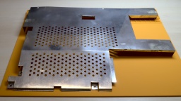
Due to my careless storage in the cellar, the metal shielding got a bit of rust over the years. I removed the worst rust spots with a fiberglass pen. Then I polished the shields with Nevr-Dull wadding polish, which removed a lot of the rust film. The result is still far from perfect, but it's hard to impossible to restore the original look of the shielding, so I decided to keep it that way.

The upper shield after removing the rust and polishing.

PSU

I have already prepared the PSU in in the last part. Now that I also got the PSU case back, it's time to put it together. I've first replaced the power switch, as the old one got broken over the years. Luckily it's a standard switch that can still be found at electronic shops.

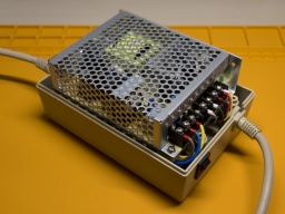
The RT-65B in its new housing. The photo shows an early attempt with swapped mains and power cables.

The Mean Well RT-65B fits into the case surprisingly well, almost as if it was made for it. I only had some difficulties to find a proper position for the wires. I tried different positions, and also tried to switch the sides of the mains and Amiga power cables.

The best result seems to be the original orientation of the cables (mains cable at the side of the power switch). With a bit of tweaking, I could finally route all the wires properly, make the RT-65B fit in, and close the PSU case.

I recommend to check the correct wiring (especially of the earthing) and the voltages once again. Also make sure that the terminals are firmly closed, and that no wires are overly bent, squeezed, or punctured.

GOEX Drive

The GOEX drive optionally comes with an OLED display that sits on top of the Amiga case and shows the currently selected file, and the current disk track. I can really recommend to order that display with the drive, as it makes selecting a file a lot easier. Unless of course you use the "GOEX on pills" version that offers a disk menu on the screen as OSD, but I wasn't sure how this version would interfere with the RGB-to-HDMI converter I am using.

The display is readily assembled, and already has crimp connectors at the end of the cable. The idea was to push them through an opening of the ventilation grille, but they just were too big for that. I had to cut them off, push the ribbon cable through an opening, and then solder new connectors to the cable.

HDMI Connector

Next problem was the HDMI connector. I use c0pperdragon's RGB-to-HDMI converter to connect my Amiga to a TV or monitor via HDMI. But where should I put the HDMI connector so I can reach it from the outside of the case?

My original idea was to cut a matching hole into the back of the Amiga case, but later I dismissed the plan and decided against disfiguring the case even further than I already did in the 1990s. A better idea was to print an expansion port cover with a hole for a HDMI cable, even though I disliked the thought that a cable would then loosely hang out of the case.

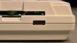
Then I noticed that the GOEX drive left a hole where the floppy drive's eject button has once been. And this hole is actually big enough for a HDMI connector, almost as if it has always been meant for that purpose.

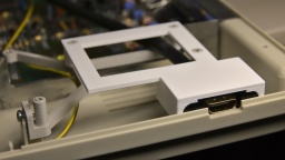
The HDMI connector fits amazingly well!The holder frame (white) sits within the frame of the GOEX drive (grey) and does not need any screws.

I designed a 3D printed frame that holds the connector of a Delock 85463 panel-mount HDMI connector. You can find the STL file at Printables for reprinting.

It looks a bit weird when a HDMI cable is plugged into that place where once the disk eject button has been, but it is working amazingly well, and saved me from cutting further holes into the Amiga case.

Completed

Now everything was mounted in its place. I couldn't close the upper shielding though, because the HDMI converter is in the way, so I decided to leave it out.

Everything is completed and in its final place.

And that concludes the restauration project. Welcome back, Amiga 500. With this hardware upgrade, you should be fit for at least the next decade.

Welcome back, Amiga!

The Kickstart Dilemma

Well, not quite. There is a Kickstart 2.04 ROM installed in this Amiga, and while playing some old games, I found out that a surprisingly large number of them crash on that version of the AmigaOS. It was indeed a big problem of the Amiga back in these days. In the previous generation of home computers, the operating system was static and was never updated, so programmers assumed to find certain routines at fixed positions. When the Amiga got popular, programmers continued to use the operating system like that, ignoring documented rules. Then in 1990, Commodore released Kickstart 2.0, a major AmigaOS upgrade. And suddenly, many poorly programmed games crashed, but instead of the programmers, the Amiga was blamed for it.

I still have an original Kickstart 1.3 ROM here, along with a ROM switch. Maybe I will use that board again. Luckily, I haven't yet closed the holes that I once drilled into the case, so I can use one for the switch again.
Amiga 500 Restauration, Part 2

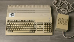
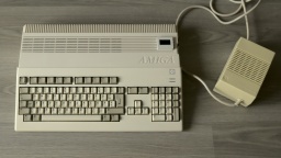
In the first part, I dusted off and checked my old Amiga 500. I've also ordered all parts for the project, and they have been delivered by now. Let's start with the restauration!

Recapping

All home computers of the 1980s and 1990s have been designed for common households, and thus had to be cheap. Commodore did not expect that the Amiga would become an "old dame" some day, so they used standard components. A common problem is that electrolyic capacitors dry out over the years, losing their capacity. Some may even leak and, in worst case, damage the board. So the first restauration step is always to replace all electrolytic capacitors, even if they should still look fine.

As I don't want to repeat that process in a decade or so, I ordered premium capacitors with an expected lifetime of 10,000 h, which is probably tenfold of the standard caps' lifetime. At the bottom of this article, I have listed all the caps on my Amiga 500 Rev 6A board.

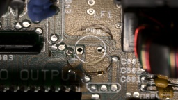
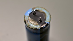
On the first sight, all capacitors seemed to be fine. Still, after removing one of them, I found traces of dried electrolyte on the board and at the bottom of the component. It really shows that a superficial inspection can be deceiving.

I also removed the wires of my self-made NMI button, and looked for cold solder joints and other potential problems. As final step, I carefully washed the mainboard with IPA.

Recapping completed!

HDMI Output

Let's start with the next construction site. As it gets more and more difficult to find TVs with a SCART connector (and I never liked them anyway), I want to connect my Amiga 500 via HDMI. Luckily there is a project by c0pperdragon that adds a pixel-perfect HDMI output to the Denise chip. The converter cannot be bought at shops, but you need to assemble it yourself. It consists of a few standard components that can be bought at good electronic shops, while the board can be ordered at PCB manufacturers. The assembly requires some fine-pitch SMD soldering though. If you don't feel comfortable with that, you maybe find a private seller for a readily assembled board.

To install the adapter, the Denise chip is removed from its socket first. Then the adapter is placed into the socket, and Denise into the adapter. A button can be connected for changing the configuration and taking screenshots, but that is not really required for operation.

The RGB to HDMI adapter. Denise is already plugged in, but the Raspberry Pi Zero is missing.

The RGBtoHDMI firmware needs to be extracted to a FAT formatted MicroSD card. Make sure to use release 20210322_f771e51 or later. Earlier releases will not work, but only show four colored rectangles.

Finally the Raspberry Pi Zero is plugged into the socket. Be very careful here! The pin header will also fit if not aligned properly, and may then damage your Raspberry or (even worse!) your Amiga.

It's easy to make a mistake here, so be extra careful that the Raspberry is properly connected.

New Power Supply

In the first part I found some liquid at the bottom of the power supply's PCB. I suspected it was capacitor liquid, but my contact at the CBM Museum Wuppertal explained me that it was just a lot of flux. Still, the old power supply would need a technical overhaul, which I can only recommend to people who know exactly what they are doing.

WARNING: Switched power supplies may still contain high voltages hours after they have been disconnected from mains. I strongly advise against attempting repairs yourself. If you decide to keep your old PSU, please ask a trained technician to restore it for you!

As I am not "trained personnel" myself, I decided against restoring the original PSU, but for replacing it by a Mean Well RT-65B. It has sufficient power, and also fits nicely into the original Amiga PSU case.

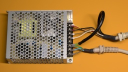
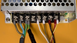
Before I removed the wires from the old PSU, I took notes on what color is connected to what voltage. Then I removed the wires, put crimp shoes on the wire endings, and connected them to the corresponding output of the new PSU.

My original PSU had a separate SEN wire. It is connected to +5V at the power plug, and is used so the old PSU could compensate wire losses and provide exactly 5V there. The replacement PSU does not provide a sense connector, so I just connected the SEN wire to the +5V line to increase the total cross-section and reduce losses, but it can also just be left open.

The "shield" wire must be connected to earth.

ATTENTION: There were different variants of Amiga 500 power supplies on the market. Your number of wires, and the wire color code, may be different. Do not just rely on my photos!

This is how it looked like after the wiring:

Mains power below, Amiga power above. Shield is connected to earth.red: +5V – black: ground – brown: +12V – white: -12V – yellow: +5V sense. Your colors may be different!Amiga 500 power connector pinout.

Do not connect your PSU to mains yet! First switch your multimeter to continuity test mode, and test if your earthing is connected to the PSU case, and to the shield and the shield pin of the Amiga power plug. After that, test if the power lines are properly connected. Now you can power up your PSU, and use your multimeter to check the voltages at the Amiga power plug.

ATTENTION: Please be very careful when you test the PSU outside the case. Make sure you cannot accidentally touch the live terminals. Also do not open the shielding of the PSU.

Test Run

After I made sure all voltages are correct, it was finally time for a first test run.

As I don't have many disks any more, I had ordered a GOEX drive as a replacement for the original floppy drive. It emulates a disk drive, but uses ADF files from a SD card. It even emulates the mechanical noises of the head stepper motor, which actually sounds much better than expected. I connected it to the floppy header of the mainboard, and used a cardboard box to make sure it won't cause short circuits.

Then I checked everything again. Is the mainboard okay? Is the HDMI converter properly connected? Is the GOEX drive connected? Is the Raspberry properly seated and the MicroSD inserted? Is nothing there that might cause a short circuit? Is the PSU protected against accidental touching the live terminators?

And then, after almost 30 years, it was finally time to wake up my Amiga 500 again.

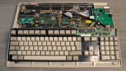
My test setup, as the case is not here yet.My Amiga is still working! And a quick hardware test also shows no damage.

I first booted an Amiga Test Kit disk and checked the RAM and the CIAs. After that, I ran some demos. The picture quality of the HDMI converter is stunning!

Meanwhile I also got the case and keyboard back from the whitening service. I cannot wait to put it all back together, and enjoy my shiny new Amiga 500.

Capacitor List

The caps list of my Amiga 500 Rev 6A, and the replacement parts I used:

Qty Type Reference Manufacturer Number
2 3300µF 10V C401 C402 Panasonic EEU-FR1A332
1 470µF 16V C307 Panasonic EEU-EB1E471
6 100µF 16V C811 - C816 Panasonic EEU-FR1E101B
2 47µF 16V C821 C822 Panasonic EEU-FR1H470B
4 22µF 35V C303 C304 C324 C334 Panasonic EEU-FR1H220
2 10µF 35V C306 C712 Panasonic EEU-FR1H100B

Notes:

  • All capacitors are radial and have a lead spacing of 5mm.
  • C401, C402: Height should be 24mm or less to fit under the shielding.
  • C324, C334: Bipolar caps may enhance audio quality. I haven't tested that though.
  • You can use any fitting capacitors with the same capacity and the same (or higher) voltage.
  • Temperature rating should be 85°C or, even better, 105°C.