Amiga 500 Mainboard

Dev

Little Java Regex Cookbook

Regular expressions, or short "regex", are a pattern of characters and metacharacters that can be used for matching strings. For example, the pattern "gr[ae]y" matches both the strings "gray" and "grey".

While regular expressions are an integral part of other popular languages, they have been introduced to the Java world rather late with the release of Java 1.4 in 2002. Perl, certainly the mother language of modern regexes, already turned 15 that year.

Regexes are sometimes hard to understand, but once you got the hang of them, they will soon become your weapon of choice when you have to deal with texts.

In this article, I focus on Java code patterns for common scenarios. If you have never heard of regular expressions before, the Wikipedia article and the Pattern JavaDoc are good starting points. The Regex Crossword site is a great place for working out your regex muscles.

Continue reading...
Enable Synology's hibernation debugger

If you own a Synology NAS, you probably know the trouble that it frequently wakes up from hibernation without any obvious reason. Synology has added a more or less undocumented debugger for that issue. If enabled, it will log the reason for waking up from its beauty sleep, so one can take measures against it.

WARNING: This article is targeted at experienced Linux users. Even if you manage to enable the debug mode, you still have to analyze the log files, find a solution to your individual problem, and assess if it is safe to apply. If you make a mistake, you can cause a lot of damage to your system and your data. Please take this advice seriously.

In any case, make sure your data is properly backed-up. Remember that a RAID is not a backup!

Also note that the debug mechanism has changed from time to time, so it may be completely different on your NAS depending on the DSM version that is used.

Continue reading...
Thunderbolt and Lightning

 The Kaminari Lightning Detector Pyramid I recently found an article about the AS3935 Franklin Lightning Sensor. As I am already recording some weather data, it immediately raised my interest.

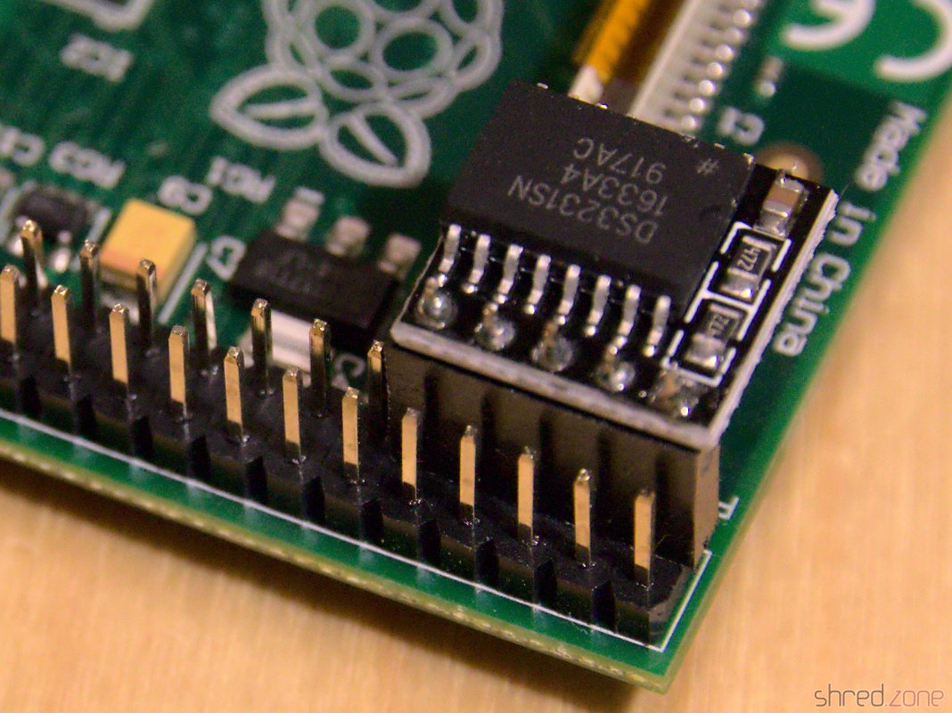
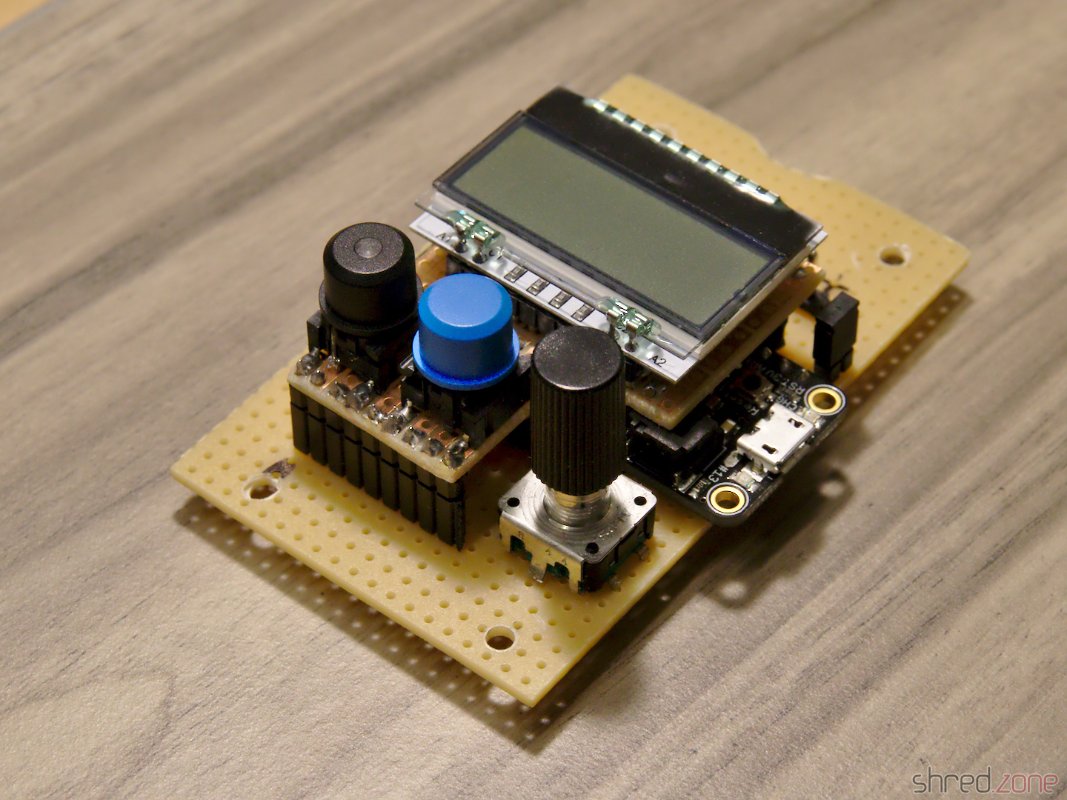
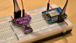
The sensor module can be found at many online shops selling products from China. It is not really cheap, but still affordable. I decided to use an ESP8266 as microcontroller, so I can read the sensor data by WLAN. The sensor is connected to the ESP via SPI. There was also some space left for a SK6812 RGBW LED indicating the sensor status.

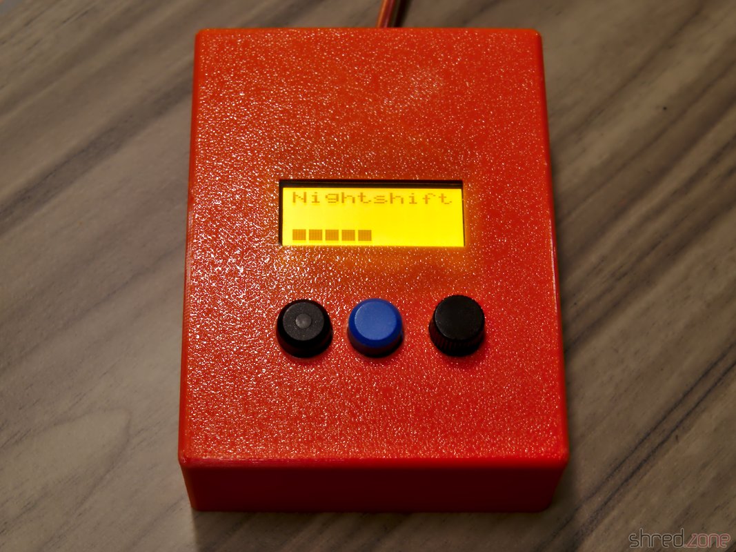
The result of this project can be found at GitHub. It's called Kaminari (which is Japanese for lightning), and also comes with OpenSCAD files for a 3D printed, pyramid shaped case with illuminated tip. In this article I will explain a bit about how I developed the Kaminari firmware.

The first problem was the calibration. The sensor is roughly pre-calibrated, but must be fine-tuned to 500 kHz ±3.5% via the TUN_CAP register. For this purpose, the antenna frequency can be routed to the IRQ pin and then be measured by the ESP. I chose to prescale the frequency by a ratio of 128, giving an IRQ frequency of 3,906.25 Hz. For measurement, I've set an IRQ handler that is just counting up a variable on each interrupt. I then reset the counter, wait for 1000 ms, then read the counter, and get the IRQ frequency in Hz units. It's not 100% accurate, but good enough for this purpose.

The TUN_CAP register offers 16 calibration steps. Just incrementing it until the frequency matches, would take up to 16 seconds. Instead I used an algorithm called successive approximation to find the correct calibration value in only 4 iterations, taking a quarter of the time.

 The AS3935 connected to an ESP8266 To my disappointment, it turned out that the manufacturer of my module (CJMCU) has used nonstandard components, so my module could only reach a maximum frequency of about 491 kHz. I first suspected that the ESP might be too slow for this kind of measurement, but a scope connected to the IRQ pin confirmed the frequency. Well, it is still within the required tolerance, but it gives a suboptimal tuning result and renders the TUN_CAP register useless.

The next problem is finding a good noise floor level. This is some kind of background radio noise filter. If the level is too low, the sensor cannot operate properly because of interfering background noise. If it is set too high, the lightning detection quality declines.

The noise floor level cannot be calibrated just once at the start. Radio noise sources come and go, may it by turning on an electronic device or just by a change in the weather. I did some experiments, and the most promising solution is a kind of tug-of-war. When the AS3935 detects too much noise, it triggers an interrupt, and the noise floor level is raised to the next higher step. If the last level change was 10 minutes ago, the ESP attempts to reduce the level by one step.

In order to reduce the number of level changes, I have added a counter. Each noise interrupt increments the counter, and every 10 minutes the counter is decremented. The level is raised when the counter reaches 2, and lowered when the counter reaches -2.

Sometimes I noticed a "noise level runaway", where the AS3935 triggers a lot of noise interrupts in a very short time, raising the noise floor level to its maximum value immediately. To stop that behavior, further noise interrupts are being ignored for one minute after a noise interrupt has been processed.

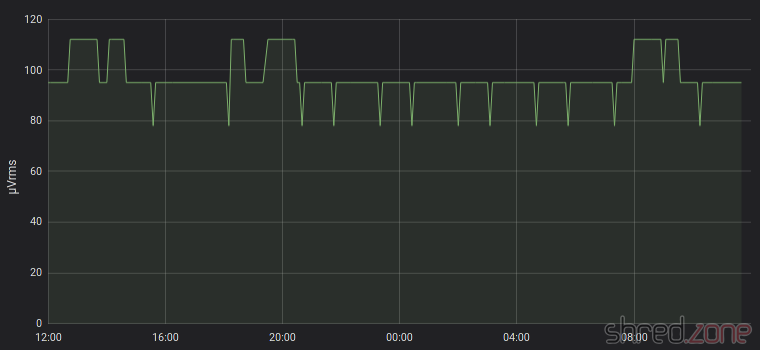
Now the noise floor level has settled to an average of 95 µVrms here. In the graph, one can see that the level is raised at some time, but then reduced again after a while. One can also see the frequent attempts to lower the level a bit further, immediately followed by a raise back to the average level. It seems that the AS3935 and the ESP have negotiated a good compromise. 😉

The AS3935 seems to be set up in an optimal way now, but I still get some false lightning events from time to time. There are a few registers left to experiment with, namely WDTH (watchdog threshold), SREJ (spike rejection) and MIN_NUM_LIGH (minimum number of lightning). I have raised the watchdog threshold to 2, and did not have a false lightning event since then.

Now I have to wait for some real lightnings… 😄

DS3231 RTC on Raspberry with Fedora

A minor downside of the Raspberry Pi is that it is not equipped with a battery backed-up real-time clock. After every reboot, the system time is messed up and needs to be corrected by NTP, which in turn requires a network connection.

Luckily, there are readily assembled RTC modules available. They base on the DS3231 real time clock chip. A tiny battery is keeping the time when the Raspberry is disconnected from power. You can find those modules for less than two Euros a piece at marketplaces like Amazon, eBay, or Alibaba. The module is just plugged onto the pin header of the RasPi.

It is quite easy to use the RTC on Raspbian. On Fedora for Raspberry Pi, the installation was a little more tricky though.

In a first step, the RTC must be added as a new I²C device:

/usr/bin/echo ds3231 0x68 > /sys/class/i2c-adapter/i2c-1/new_device

(If you have a Raspberry Rev 1, you'd use /sys/class/i2c-adapter/i2c-0/new_device instead.)

The RTC does not store the time zone, so we need to tell the system that we'd like to use the system's time zone:

timedatectl set-local-rtc 0

And finally we copy the current system's time to the RTC chip:

hwclock -w

The RTC is now set up and ready for operation. But we're not done yet. When the system boots up, the DS3231 is unknown to the system again. We have to add a systemd service for adding it and reading the time, by creating a file called /etc/systemd/system/my-rtc.service with the following content:

[Unit]
Description=Enable battery backed-up RTC
Before=basic.target
After=sysinit.target
DefaultDependencies=no

[Service]
Type=oneshot
RemainAfterExit=yes
ExecStartPre=-/usr/bin/bash -c '/usr/bin/echo ds3231 0x68 > /sys/class/i2c-adapter/i2c-1/new_device'
ExecStartPre=-/usr/bin/sleep 0.2
ExecStart=/usr/sbin/hwclock -s

[Install]
WantedBy=basic.target

The service is enabled via:

systemctl enable my-rtc

And now every time the system boots up, the DS3231 is added as I²C device and the system clock is set to the time found in the RTC. If a network is available, NTP will later take over and set the network time.

It's not the most elegant solution, I guess. I had to add a sleep command because it turned out that the hardware is not immediately available after adding the device. I'd like to hear from you if you found a better way.

Remember to manually use hwclock -w from time to time, to reset the RTC to the correct time. If you shut down your RasPi frequently, you could add another systemd service that automatically writes the current time on system shutdown.

Premium Wall Bias Lighting, Part 3

I haven't forgotten about you. Some private stuff kept me from completing this project for a while. To make it up, I have added OpenSCAD files for a 3D printed case.

The controller was a little tricky to complete, mostly because of the very different component heights. I decided to use two circuit boards that are stacked onto each other by headers.

On the upper board, there are only the two buttons and the LCD, as well as the transistor and resistor for the LCD backlight. As I only used one-layer TriPad strip boards, I had to use this one upside down for the male headers to point downward. This rather unconventional use made it a little tricky to solder the buttons and LCD headers on the actual bottom side of the board.

The soldered controller boards. The lower board contains all the other components, as well as the wiring. The rotary encoder also made it to the lower board, because it is much taller than the other buttons. This way, the top of the button caps are almost level and nice to look at.

The result is surprisingly compact for a DIY solution. The button caps and the LCD are just perfectly positioned for a case.

With plastic feet attached, you can use the controller as it is. You can also get a plastic case with transparent top, drill three holes in it for the button caps, and mount the sandwich with spacers. But if you have the chance, you should definitely go for a 3D printed case.

I have set up a project at GitHub. It contains the circuit diagram, the bill of materials, the firmware source code, and OpenSCAD files for a printed case. There is no firmware binary yet, as you need to adapt the source code to the length of your LED strip anyway.

You will find the OpenSCAD files for the case in the GitHub project. There are bonus OpenSCAD files in the project, for printing a customized case. Due to the absence of properly layouted PCBs, I am aware that each controller is going to look differently when finished. In the parameter.scad file, you can change all kind of parameters, so you should be able to make your individual case in, well, almost any case (silly pun intended). 😄

The SPI flash memory of the Feather M0 Express is not used yet. In a future release, I may add a settings menu for the LED strip size. The controller is also forgetting all its settings when disconnected from the power. This needs to be addressed in a future release as well.

But after all, this is a start for your own DIY wall bias lighting. Feel free to send pull requests for enhancements!

Again, remember that you must remove the jumper before connecting the Feather to an USB port, otherwise your computer will be damaged.