Alps, Munich

#Retro

R Tape loading error, Part 2

In the first part I showed how the Sinclair ZX Spectrum stored data on tape. This second part explains what is stored, and what causes a tape loading error.

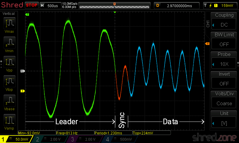
The ZX Spectrum BASIC offers a SAVE command for saving all kind of data. It can be used to save a BASIC program, variable arrays, but also arbitrary parts of memory. These files are always saved in two separate blocks. The first block is called header. It contains the file name, data type, and other meta information. The second block follows about a second later and contains the data itself.

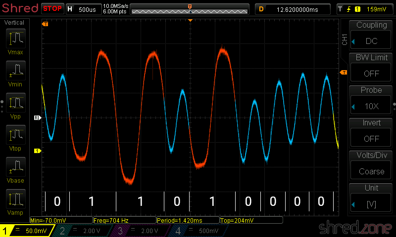
The internal structure of each block is identical. The first byte distinguishes between header ($00) and data blocks ($FF). The final byte is a parity checksum. Everything between these two bytes is the payload.

A header block always contains a payload of 17 bytes. The first byte identifies the file type, followed by the file name (10 characters), followed by the length of the data block, and closed by two optional parameters that have different meanings depending on the file type. The length and the two parameters consume two bytes each, with the lower byte coming first because the Z80 CPU is little endian.

This is an example header block of a screenshot:

00$00 = Header
0003$03 = Binary file (Code or SCREEN$)
0153S
0268h
0372r
0465e
0564d
062E.
077Az
086Fo
096En
1065e
11001BLength: 6912 bytes ($1B00)
130040Parameter 1, here: starting address ($4000)
150000Parameter 2, here: unused
20Parity

A screenshot is actually just a memory dump that starts at address $4000 (which is the starting address of the screen buffer) and is exactly 6912 bytes long (the ZX Spectrum has a resolution of 256×192 monochrome pixels plus 32×24 bytes color attributes, giving a screen buffer size of 6912 bytes).

For other file types, the two optional parameters have different meanings. For example, a BASIC program file stores the line number to start at after loading.

The final byte is the parity. It is used for error detection, and computed just by XOR-ing all the bytes that have been read. The result must be $00, otherwise a "R Tape loading error" is reported.

This kind of error detection is rather weak. Due to the nature of the XOR operation, two wrongs give a right. This means that when the block contains an even number of bad bits at the same position, they will be undetected. It is also not possible to correct reading errors, as the XOR operation only allows to identify the position of the bad bit, but not the actual byte that contained the error. More sophisticated error correction algorithms would have slowed down the loading process, though.

The parity is computed as a final step, after all the bytes have been read from the block on tape. For that reason, the loader can only decide at the end of the recording whether the loading was successful or not.

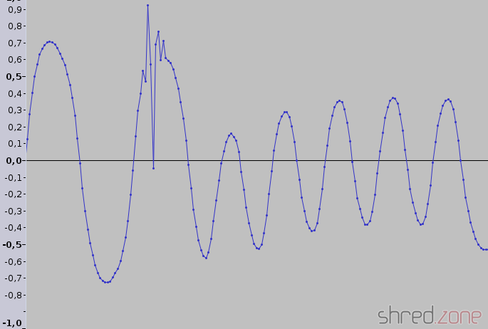
But then, why does the tape loading error sometimes appear while the block is still loading? Well, in the first part I have explained that the loading routine just reads an unknown number of bytes. It ends when waiting for a pulse change took to long. Now, if there is an audio gap on tape, the signal seems to end just in the middle of the block. It is then very likely that the parity checksum is wrong because there are still bytes missing.

Some simple copy protections made use of the way the Spectrum loads data from tape. A very common way were “headerless” files, where the header block was left out and only the data block was recorded on tape. The BASIC LOAD command was unable to read those files because of the missing header.

R Tape loading error

In the early time of home computers, at the beginning of the 1980's, hard disks and even floppy disks were too expensive for home use. The cheapest way for storing large amounts of data was the cassette tape. Cassettes and tape recorders were affordable and available in almost any household.

In this blog article, I'm going to explain how the Sinclair ZX Spectrum stored programs on cassette tapes. Other home computers of that time, like the Commodore 64 or Amstrad CPC, worked in a similar fashion.

Cassette tapes were designed to store audio signals like voice or music, so the inventors of the home computers had to find a way to convert data to audio signals. The easiest way is to serialize the data to a bit stream of 1's and 0's, and generate a long rectangular wave cycle for "1" and a short rectangular wave cycle for "0". This is what the ZX Spectrum actually does!

A short wave cycle is generated by giving power to the audio output for 855 so called T-states, and then turning off the power for another 855 T-states. A "T-state" is the time of a single clock pulse of the Z80-A CPU. As the CPU of a classic ZX Spectrum is clocked with 3.5 MHz, a T-state has a duration of 286 ns. The duration of a short wave cycle is thus 489 µs, giving an audio frequency of about 2,045 Hz. The long wave cycle is just twice as long.

Due to all kind of filters in the analog audio path, the rectangular signal is smoothed to a sinusoidal signal when played back. A Schmitt trigger inside the ZX Spectrum's hardware converts the audio signal back to a rectangular shape. Since the audio signal can have different amplitudes or could even be inverted, the hardware only cares for signal edges, not for levels. All that the loader routine now has to do is to measure the duration of the pulses, regenerate the bit stream, and put the bytes back together.

If you think that things cannot be that easy, you are right. 😄 The most difficult part for the loader is to find the start of the bit stream. If it is off by only one cycle (or even just a pulse), all the bytes are shifted by one bit, and the result is useless. All kind of noise on the tape makes it impossible to just wait for the signal to start, though.

For this reason, the recording starts with a leader signal, followed by a sync wave cycle, followed by the bit stream itself. The leader signal is just a continuous wave with a pulse length of 2,168 T-states, giving an 806 Hz tone that is displayed by red and cyan border colors on the TV. The sync wave cycle is a pulse of 667 T-States "on", followed by 735 T-states "off". After that, the actual data stream begins, which is displayed in blue and yellow border colors. When the last bit was transmitted, the data stream just ends.

So when the ZX Spectrum loads a file from tape, it first waits for the 806 Hz leader signal. If it was detected for at least 317 ms, it waits for the sync pulses, then it starts reading the bit sequence until there is a timeout while waiting for the next pulse.

It is a very simple way to store data on tape. And still, it is surprisingly reliable. After 30 years, I could recover almost all files from my old cassette tapes. Some of them were of the cheapest brands I could get my hands on back in 1987.

The only disadvantage is that this method is very slow. With 489 µs for a "0" and 978 µs for a "1", saving just 48 KBytes of data can take up to 6 minutes, giving an average bit rate of 1,363 bps (yes, bits per second). If we were to save a single 3 MBytes mp3 file that way, it would take almost 5 hours (and 5 cassettes with 60 minutes recording time each).

Some commercial games used speed loaders and copy protections. Speed loaders just reduced the number of T-states for the pulses, which increased the bit rate. Some copy protections used a "clicking" leader tone, where the leader signal was interrupted before the minimal detection time of 317 ms was reached. The original loader routine could not synchronize to these kind of signals, so it was impossible to read those files into copy programs. Those protection measures could still be circumvented by copying directly from tape to tape, but this only worked a few times due to increasing audio noise.

In the next article, I will take a deeper look at the bit stream contents, and I will also explain where the dreaded "R Tape loading error" comes from.

Recovering old ZX Spectrum tapes, Part 2

The ZX Spectrum was a comparable cheap home computer, and thus the tape loading and saving mechanisms have not been very sophisticated. The tape recording is just a stream of short waves (0 bit) and long waves (1 bit). The stream starts with a leader signal (a series of even longer waves) and a single sync pulse. So, in the theory, reading a tape recording means measuring single wave lengths, by taking the time between two zero-crossings, and converting them into a sequence of bytes.

But then again, we are dealing with 1980's analog technique. In practice, we will find signals like this. A click produced an additional zero-crossing that is to be ignored. Also, the amplitudes and DC offsets change all the time.

And pooof... There went another week of nightly hacking Python code, having very close looks at audio waves, and searching for clues about why tzxwav won't behave like I expect it to behave. But I think the result is worth looking at now! tzxwav now reads almost all of my tape samples without those dreaded CRC errors. If there are CRC errors, the sample was usually so damaged that it would need manual restauration.

And as a bonus, it is now almost twice as slow as before. 🤭 But speed was never a goal anyway, as people are likely to convert their old tapes only once.

Recovering old ZX Spectrum tapes

The author, on Christmas Eve 1985 Since I am in the mood of heavy ZX Spectrum retro action, I dug out all my old computer tapes in an attept to digitize and convert them. It turned out to be more difficult than I thought...

The first trouble was to find a tape player. I had disposed my last tape recorder a couple of years ago. The new ones I found at Amazon looked nice on the first sight. They could be connected to the USB port or even digitize the tapes straight to an USB stick. The customer reviews were scaring off: cheap plastic, poor sound, digitizing to USB stick was only possible on battery power... I had more luck on eBay, where I found a genuine 1990’s Aiwa Walkman (it’s even a recorder, with auto reverse and Dolby NR) in good condition for about the same price.

I connected the Walkman to my computer’s microphone input using a cable with 3.5mm stereo jacks, selected the correct tape type (Normal or CrO2), and turned off Dolby NR. Then I digitized right away, using Audacity for recording and post processing. I used 16 bits per channel, and a 44100 Hz sampling rate. The ZX Spectrum provided a mono signal, so I chose the left or right channel (depending on the quality) and discarded the other one. Mixing down the stereo signal turned out to be problematic, as well as using a lossy file format like ogg.

The WAV files can be loaded into the Fuse Emulator, but it’s better to convert them to TZX files, as they are much smaller. There are a few tools for that, for example audio2tape that comes with Fuse. I wasn’t satisified with the result though, as the generated TZX files contained many CRC errors. MakeTZX is also worth a try, as it supports digital filters, but I was unable to make it run on Linux. Some other converter tools are for Windows only, and thus not very interesting. 😉

So I found myself writing a set of TZX tools in Python. It contains tzxwav, that’s yet another tool for converting WAV files to TZX files, but is robust against poor audio quality. It took me three weeks of work, and about 30 hours of tape material, until it was able to successfully read almost all of my tape recordings.

An advantage of TZX files is that they contain the raw ZX Spectrum binaries, so they are very easy to extract. tzxcat allows to retrieve single binaries from TZX files, which can then be converted into PNG files, BASIC sources or whatever, provided there are converters for it.

What I have now are TZX files of all my old ZX Spectrum tapes. It was very interesting to rediscover my old files, screens, programs and source codes. In 1987 and 1988, I wrote a lot of more or less useful tools, designed several fonts and completed two demos.

Optimizations

On a slow processor like the Z80, it is essential to think about execution time. Often a clean approach is too slow, and you need to optimize the code to make it a lot faster.

The ZX Spectrum screen bitmap is not linear. The 192 pixel rows are divided into three sections of 64 pixel rows. In each of these sections, all the 8 first pixel rows come first, followed by the second pixel rows, and so on. The advantage is that when writing characters to the bitmap, you only need to increment the H register to reach the next bitmap row. The disadvantage is that a pixel precise address calculation is hell.

This is how the coordinates of a pixel are mapped to the address:

HL
1514131211109876543210
010Y7Y6Y2Y1Y0Y5Y4Y3X7X6X5X4X3

X2, X1 and X0 represent the bit number at the address. It can be used as a counter for right shift operations.

My first attempt was a straightforward code that shifted, masked and moved the bit groups into the correct places. It took 117 cycles. This is nice, but we can do better.

We need a lot of rotation operations to shift the bits to the right position. Rotation is a rather expensive operation on a Z80, because there are no instructions that rotate by more than one bit at a time. My idea was to divide the X coordinate by 8 (by rotating it three times to the right) and simultaneously shift Y3 to Y5 into the L register. With a similar trick, I could set bit 14 while rotating, which saved me another or operation with a constant.

This is the final optimized code. It takes the X coordinate in the C register, and the Y coordinate in the B register. The screen address is returned in the HL register pair. BC and DE are unchanged, so there is no need for expensive push and pop operations.

pixelAddress:   ld      a, b
                and     %00000111
                ld      h, a    ; h contains Y2-Y0
                ld      a, b
                rra
                scf             ; set bit 14
                rra
                rra
                ld      l, a    ; l contains Y5-Y3
                and     %01011000
                or      h
                ld      h, a    ; h is complete now
                ld      a, c    ; divide X by 8
                rr      l       ; and rotate Y5-Y3 in
                rra
                rr      l
                rra
                rr      l
                rra
                ld      l, a    ; l is complete now
                ret

It only takes 108 cycles, ret inclusive. Optimizing saved me 9 cycles (or about 8%). This doesn’t sound like much, but if the code is invoked in a loop, those 9 cycles are multiplied by the number of loop iterations.

I claim this is the fastest solution without resorting to a lookup table. Try to beat me! 😁