Clockwork

#Retro

Action Replay

I got this Action Replay MK-I module. According to the seller it was untested, and for that reason sold as defective. It was in a… let's say very used state. The case was dirty, to a point that it was almost revolting to touch it. A side of the case was cracked open, and a knob was missing. The module must have been dropped at some time.

The Action Replay, in the sad state that I got it.

I carefully opened the case. The top and bottom shells are just stuck together, there are no screws, so it was easy to pull them apart. Inside I found some kind of coating on the PCB, so perhaps a drink had been spilled on the module as well. I also found a lot of fine paper dust like from a cardboard, and a small dent at the corner of the PCB that was caused by the drop.

Even the inside is filthy.

The first thing I did was to give the entire module a proper cleaning in an ultrasonic cleaner, just with warm water and a drop of dishwasher detergent. And yes, I also washed the PCB that way, then dried it off and sprayed it with IPA to remove the last traces of water. That bath did wonders.

Before cleaning: Dirt everywhere, and also this strange matte coating on the PCB. After cleaning, the board looks almost as new. I removed a few parts before the bath.

I expected that the dirt also reached the inside of the mechanical parts, so I decided to replace them all. They were a bit hard to find as replacement parts, but still available. As the original knob was lost, I used a different potentiometer that came with a knob. Unfortunately the new one is white, while the original one has likely been black, so I couldn't fully restore the original outside look.

New electrolytic condensors and mechanical parts for the rejuvenating cure.

The case was cracked open at one side because two pins inside were broken off. I fixed the pins with superglue. After that I exposed the case to the sun for a day, which removed quite a bit of the yellowing. Then I could put everything together again. Compared to the original state, the Action Replay is now looking nice and clean.

The Action Replay, shiny and as good as new.

I gave it a test run in my Amiga 500, and it was working fine! Now I have an Action Replay for my Amiga collection. The only sad thing is that it cannot be upgraded to an MK-II or MK-III, as these modules are constructed differently.

Amiga 1200 Restauration

Ever since I got my Amiga 4000, I was pondering about if an Amiga 1200 would have been a better choice. I mean, the Amiga 4000 is nice because it has a lot of space for extensions. But on the other hand, it is rather bulky and heavy, so it isn't much fun to take it to a friend or a party, unlike the compact and light Amiga 1200.

But why not have both? πŸ˜‰ I had found an Amiga 1200 offer on the Bay that was too good to be ignored, so I bought it.

My new Amiga 1200, unboxed. The keys are yellowed, and the Amiga badge is just a cheap sticker.

It's an Amiga 1200 from the days after Commodore went belly up, and when Escom took over and sold the last Amiga stocks. The good news is that the Escom cases were made of ABS with an anti-UV treatment, so they will never yellow. The bad news is that the keycaps were not treated, and are very visible yellowed by now.

I sent the keycaps to the experts at the CBM Museum Wuppertal for whitening. The case itself is almost in a mint condition, all it needed was a bath in warm dishwater.

Let's take the computer apart and have a look inside.

After opening the cover and removing the keyboard.

There's a 2.5" hard disk, which turned out to contain a Workbench, a few games, and also many bad sectors. I'm going to replace it with an SD Card solution anyway. The shielding has a bit of flash rust and was bent around the ROMs, probably from forceful prying out the ROM chips with a screwdriver. Besides that, the overall status is quite okay.

The mainboard is in a good condition. I've already changed the Kickstart ROMs.

Under the shielding, I found the mainboard in a good condition, especially without flash rust on the modulator. To my surprise, it is a Rev. 1D.1 board, which was actually the first broadly sold board revision. In one of the last Amigas that have ever been produced, I had rather expected to find a revision 2 board. Anyway I was lucky because the 1D.1 revision is said to be the most stable one, and it also has a good Lisa chip that was manfactured by HP. On both CIA chips I found traces of flux, so the board seems to have been repaired before.

It's a rather early Rev 1D.1 board. I didn't expect to find that in one of the last Amigas ever sold. It also seems that this board has been repaired before.

According to my contact at the CBM Museum Wuppertal, Escom sold everything they could find at the Commodore remainders. Allegedly they also produced "new" Amiga computers with refurbished mainboards. Maybe this is one of them?

I first inserted diag ROMs and checked the hardware, but found no problems, so I upgraded the system to AmigaOS 3.2. The next thing on my to-do list was to replace the electrolytic capacitors, as they tend to leak over all those years, causing damage to the PCB. I have already done that on my Amiga 4000 before, but on this model the space was a bit more limited. I even had to remove a freshly replaced SMD capacitor because another capacitor did not fit next to it any more.

Two capacitors are overlapping. It's a tight space. Eventually I replaced all electrolytic capacitors.

To enhance the stability of accelerator boards, it is recommended to remove the capacitors E123C and E125C on the bottom side of the PCB. The easiest way is to use two soldering irons like a pair of tweezers.

The bottom side, with E123C and E125C removed.

After a thorough wash with IPA, the board was then ready to move back into the case.

The board after recapping, ready to move in again.

I want to modernize the Amiga so it can be connected to a HDMI monitor. The RGB to HDMI solution of the Amiga 500 won't work on the AGA chipset though, so I decided to get an Indivision AGA MK3 from Individual Computers. It is plugged onto Lisa and one of the CIA chips, and offers an HDMI output even with sound. (Which is quite an accomplishment, as both chips are not connected to a sound line.)

Since I was on it, I also extended the memory with an ACA1211. Unfortunately it turned out that AmigaOS 3.2 is incompatible to the ACA1211, and the system won't boot in this combination. I had to return to the original AmigaOS 3.0 ROMs again. Eventually I traded the ACA1211 for an ACA1234, which is also an accelerator and works fine with the latest AmigaOS.

To make the wire mess complete, I replaced the floppy disk drive with a GOEX drive from Centurion Tech.

The Indivision AGA MK3 and the ACA1211 mounted. The GOEX floppy simulator replaces the original floppy disk drive.

Centurion also offers LED boards with customized colors. I have picked blue as power LED, green as floppy drive LED, and red as harddisk LED.

New LEDs in my favorite colors! 😍

In the meantime, I got the whitened keycaps back. They were almost white again, but sadly there is still a slight, but visible yellow tint. Maybe I will buy a new set of key caps once they are available. The Amiga would then look as new.

The original Escom label is just a cheap sticker. It looks ugly to me, so I replaced it with a replica Commodore badge.

And then, for the first time after my purchase, I could close the Amiga 1200 case again.

This is my refurbished Amiga 1200/030.

Please welcome the newest addition to my Amiga collection!

The Ugly Duckling

One year or so after I got my Amiga 500, I extended it with a GVP Impact Series II A500-HD+ SCSI host adapter and a 45MB harddisk. It retired together with the Amiga 500, and was stored in the basement for decades. But while the Amiga survived the years in a surprisingly good state, the GVP had suffered from the moisture. The case was yellowed, but also got mold stains, and the metal frame got some flash rust.

Dirty, yellowed, mold stains, rust at the bottom frame… This poor device has suffered from storage.

All in all, it seemed to be in a bad shape that was difficult to restore. But on the other hand, it would be sad to write off this nice piece of hardware, while all the other Amiga stuff got a general overhaul.

I sent the case to the CBM Museum Wuppertal for cleaning and whitening. It was a bit embarassing to send it in that bad condition, but they said it can be cleaned and will then look as good as new. Let's see if they can do miracles.

Flash Rust

The base frame had a lot of dirt and flash rust from the storage, especially in the areas that are frequently touched. I used some Nigrin car metal polish paste to clean it, but probably every kitchen metal polish would have done the job as well. It was a bit of work, but after that it almost looked as new.

A lot of flash rust, fingerprints, and dirt. After applying a metal polish, it was a lot harder to make a photo. πŸ˜„

Self-Powering

There have been two things that were always annoying me on this controller. One was the tiny fan that was supposed to cool the harddisk, but produced a lot of noise. The other one was that a separate external PSU was needed to power the harddisk.

I always wished that the controller would just source itself from the Amiga, but it was clear to me that the mechanical harddisk was drawing too much power for that. The original Fujitsu drive consumed about 10W! With a SCSI2SD adapter, the power consumption is considerably lower, so a self-powering is feasible. The SCSI2SD V5.2 adapter draws only about 10mA, or 0.05W.

The controller can easily be modified to get its power from the Amiga. There is a blog post by davem2 explaining it. All one needs to do is to bridge the CN5 and CN6 pads with some solder.

The CN5 and CN6 bridges enable powering from Amiga. The controller's PSU must not be connected after the modification though.

Since the SCSI2SD adapter also does not need active cooling, I could finally keep the loud case fan disconnected for good.

After the modification, make sure never to connect the GVP PSU to the controller again. It would power the Amiga via the card connector, which is very likely to cause damage to your hardware. Also, do not use mechanical harddisks after the modification. If you want to keep using the original PSU instead, you should let a technician check it first.

Firmware Upgrade

By a lucky chance, I found the latest firmware v4.15 in Ralph Babel's Amiga archive. By another lucky chance, I also found a 27128 EPROM in my spare part box that was once stripped from an old mainboard.

The original firmware would have worked fine as well, but if there is an opportunity for a free update, why not take it?

A firmware update after 30 years!

If you should use a 27256 EPROM instead, make sure to burn the image twice, as only the upper half of the memory will be accessed by the hardware.

Final Works

As there are no electrolytic capacitors on this board, there is no need for recapping. I still did a minor modification: I replaced the LEDs with blue (power) and red (disk) ones, as it became a kind of signature color for all my computers.

After that, I gave the board a thorough bath in IPA, and cleaned the edge card connector with a contact cleaner.

The PCB is nice and clean again!

I also found two 1MB/70ns 30-pin SIMM modules for a few Euros on the Bay, so I could double the available Fast RAM to stunning 4MB in total. (Remember to change the jumpers accordingly, as there is no automatic detection.)

Reassembly

Meanwhile the CBM Museum Wuppertal had returned the cleaned and whitened cover. They did an excellent job! The case looks almost as good as new. The mold and dirt stains are gone, and the whitening brought back the original "Amiga beige" color.

The cover was cleaned and whitened successfully.

As the SCSI2SD adapter is delivered without any kind of mounting frame, I had to 3D-print one myself. Unfortunately it collided with the case fan, so eventually I just removed it completely.

The SCSI2SD adapter on its mounting frame.

And that's it. The GVP harddisk controller is reunited with its Amiga 500 again. I am sure they have missed each other. πŸ˜‰

Don't they look happy?

The ugly duckling finally became a beautiful swan again!

Amiga 4000 Restauration, Part 2

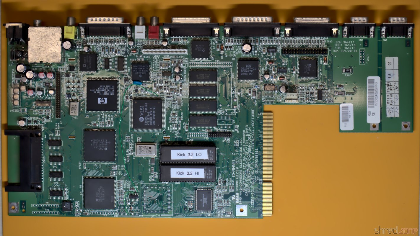
In the first part, I took the Amiga apart and repaired the main board. In this second part, I will take care of a new PSU, and then I will put the system back together.

New PSU

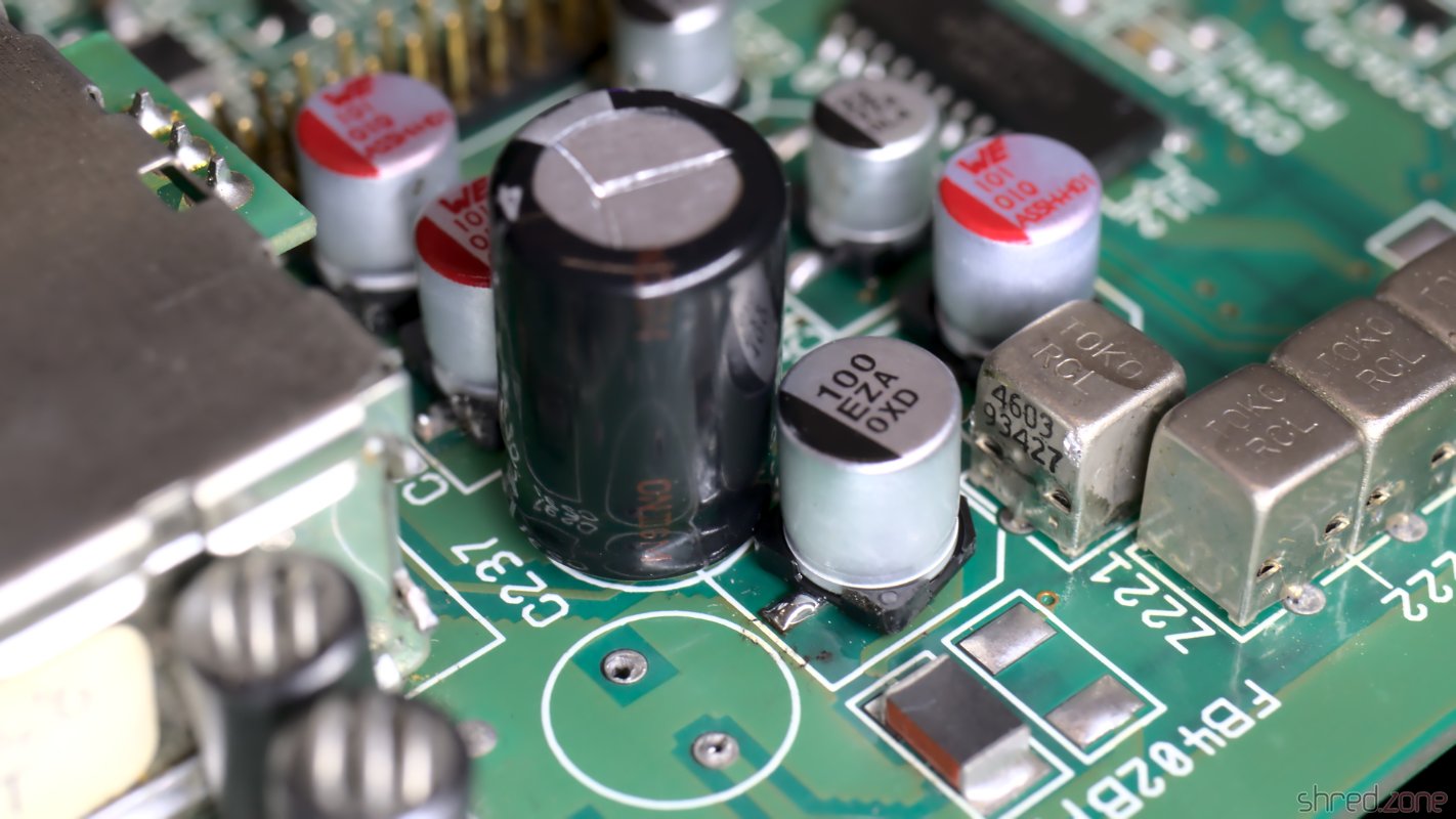
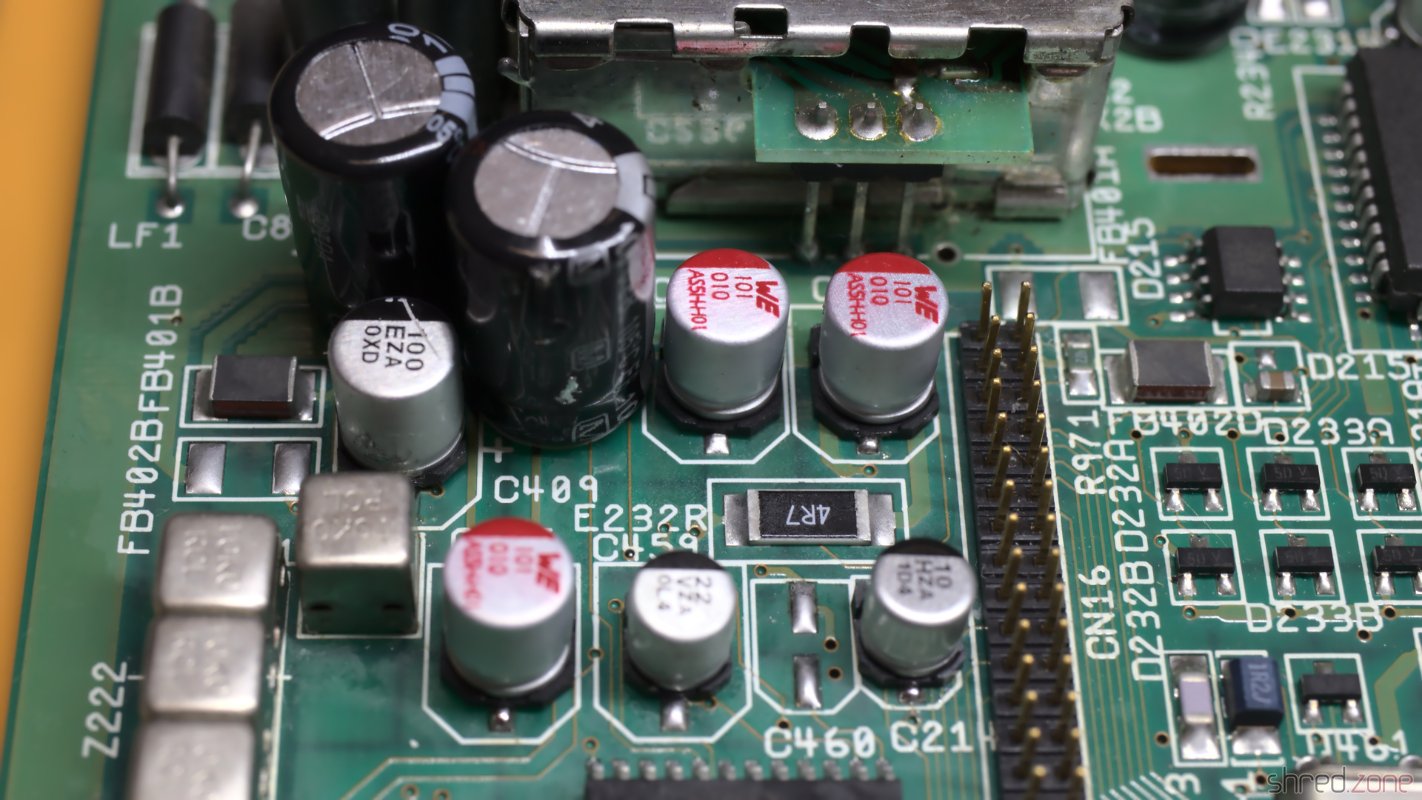
There are also capacitors in the PSU that dry out over the years and need to be replaced. But as I'm not a trained technician, I keep my hands off all kind of hardware as soon as mains power is involved.

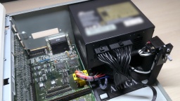
Surprisingly, a standard SFX form factor PSU perfectly fits into the power supply opening at the back side of the Amiga case. Even the two screw holes of the case match perfectly, almost as if the SFX form factor was just invented for that purpose. There is sufficient space below the PSU for the fan to transport the warm air from inside the case to the outside. There is also enough space for the longer SFX-L form factor. Most of them use a silent 120mm fan. All it needs is a frame where the power supply can sit on.

Not all SFX PSUs are suitable for the Amiga though. The reason is that in modern PCs, the main load is on the 12V line, and there is also a 3.3V line. The Amiga however has its main load on the 5V line, the load on the 12V line is neglectible, and the 3.3V line is not needed at all. Most modern PSUs are regulated on the 12V line. If there is too little load on it, the other voltages may become instable. In best case, the Amiga will then just crash. In worst case, its hardware will be damaged. There are experts who generally advise against using PC PSUs as a replacement power supply, so let me give some warnings before I go on with the article.

WARNING: I recommend to keep the original Amiga PSU, and have it overhauled by an expert. Using a different PSU may cause permanent damage to your Amiga, possibly years after the modification. Self-made power adapters can damage your Amiga if incorrectly wired, and may even cause a fire if underdimensioned or short-circuited. You reproduce the following modification at your own risk. If in doubt, keep using your original Amiga PSU.

The original Amiga 4000 power supply has a maximum load of 145W. Even the smallest SFX PSU is able to deliver far more than that, so basically you can choose any PSU which provides at least 90W (18A) on the 5V line. Still the actual choice is very small. Firstly, the PSU should generate the 5V by a separate DC/DC converter, so the voltage is stable even if there is almost no load on the 12V line. Secondly, the PSU fan needs to be active all the time, as it is the only fan in the Amiga that transports the warm air out of the case. Many modern PSUs have a hybrid fan control though, and operate in a passive cooling mode on low load conditions.

For my Amiga, I use:

  • A be quiet! SFX-L Power 500W PSU. According to the manufacturer the 5V is generated by a DC/DC converter, and all supplied voltages have a required minimum load of 0A. Also the fan is permanently operating, but still almost inaudible. Some of the connectors of the modular design collide with the power switch, but that's not a problem unless you plan to use more than three drives.
  • A 3D printed SFX adapter frame.
  • A Canal PSD-1 power switch. They are not manufactured any more, but can still be found at online marketplaces. If you cannot get one, you can also take the one from your original PSU. (Do not open the PSU case, but ask an expert to remove it for you.)
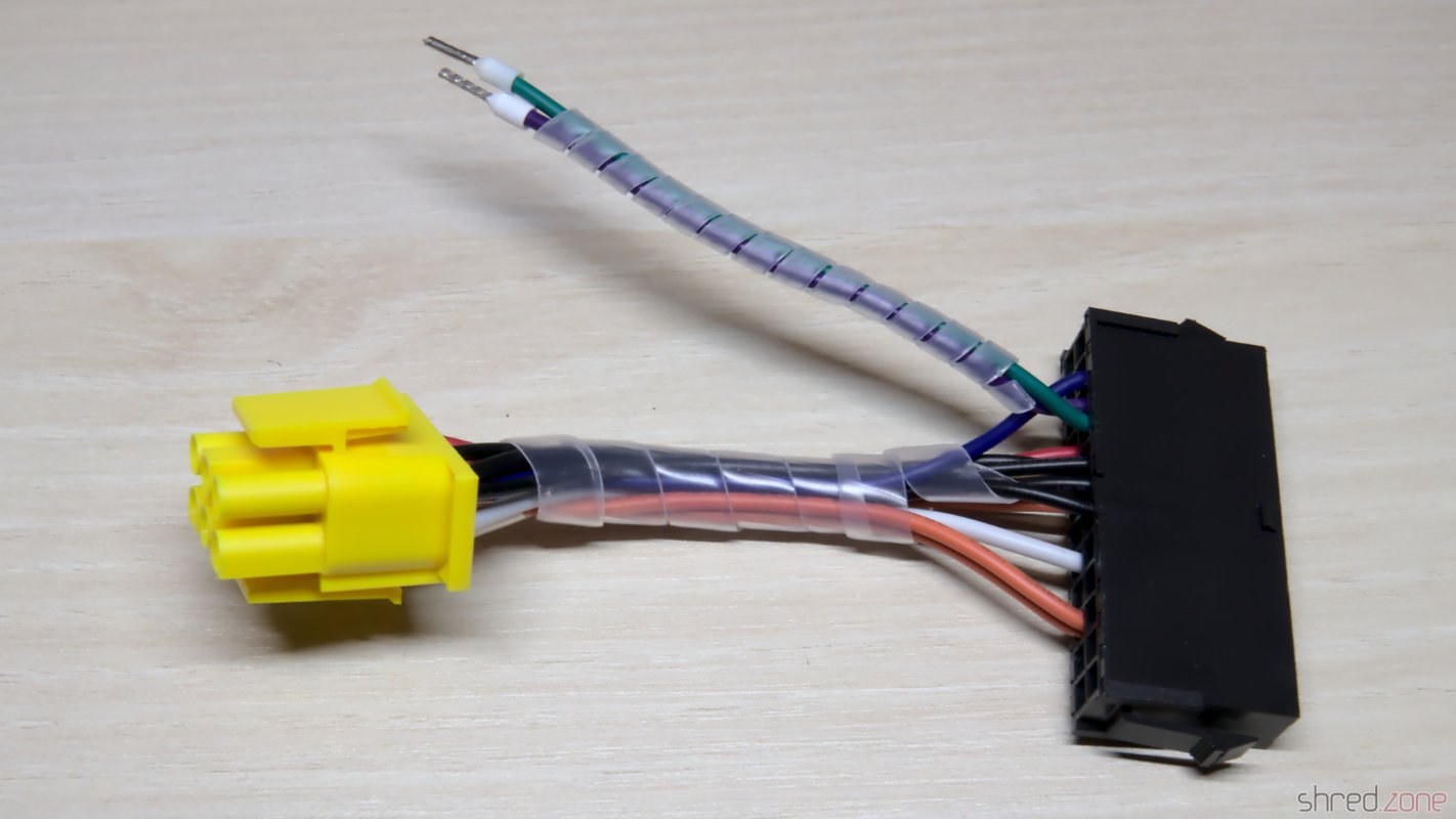
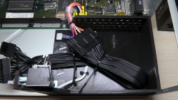
  • An ATX to Amiga power adapter. I made one myself using an "ATX to Acer 12-pin" power adapter, a TE Connectivity Mate-N-Lok 6 circuit plug that is still available today, and a crimp tool. Some Amiga shops also sell readily assembled adapters.

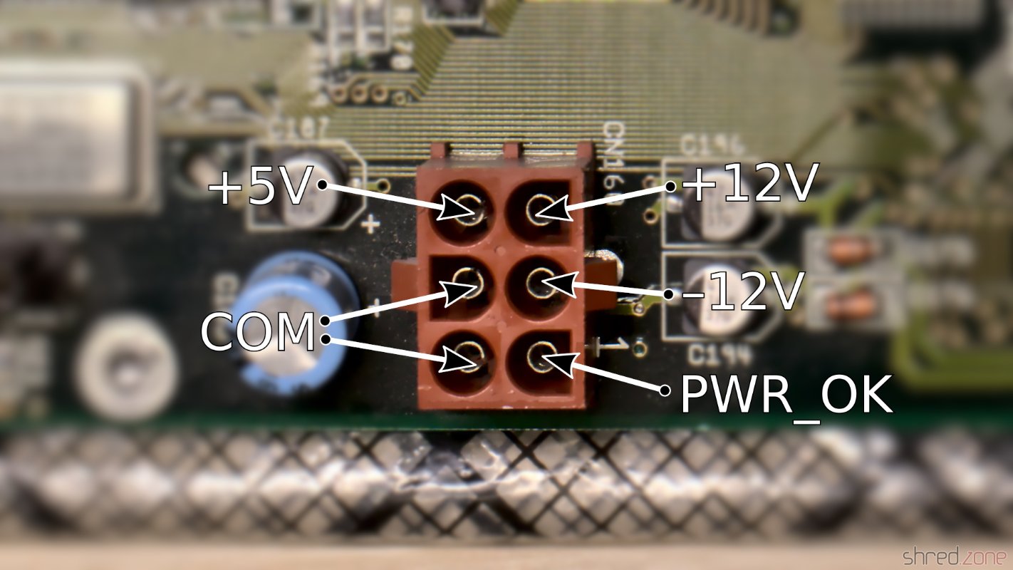
To build the power adapter, the wires need to be connected between the Amiga power plug and the corresponding pin of the ATX power connector. The PS_ON# and one of the COM pins are connected to the power switch. All wires should be sufficiently dimensioned.

Pinout of the Amiga 4000D power connector.The self-made ATX adapter, with two extra wires for the power switch.

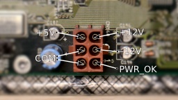
When everything is assembled, make sure (make double sure, make even triple sure) that the wiring is correct, but do not plug the connector into the mainboard yet. Now press the power button and check the voltages. PWR_OK should have 5V, but it may flutter or even be 0V because the PSU has no load right now. The other voltages must be correct and within a tolerance of 5%. Keep the test short, as it may stress the PSU.

For the first live test, I removed the CPU module, the SIMMs, and all Zorro boards. The Amiga won't boot like that, of course. But if something should go horribly wrong, the damage would be limited to the mainboard only (which is still bad enough).

The ATX cable and adapter cable is zip-tied to the frame.The PSU is seated on the frame. Everything is ready for a live test.
 I blurred the label because the PSU model that I used for this photo had a hybrid fan controller and was unsuitable for the Amiga.

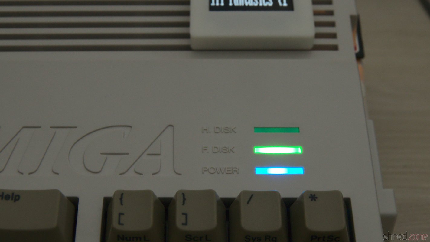
Then I turned on the power, for the first time in maybe 20 years. The power LED lighted up. There was no smoke, no smell of burnt electronics, all the chips stayed cool. I checked the power lines, and all voltages were within the expected range. This was looking really good! I turned the power off again.

Now I was confident enough to remount the CPU module and the SIMMs. I also inserted a scandoubler, and connected a monitor to it. Then I turned the system on again. And a few seconds later, I got a picture.

Alive again! The picture quality is poor because the signal is out of the monitor's range.

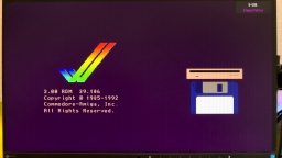
I was probably never that happy to see the Amiga boot screen! πŸ₯²

I had invested some money and many weekends into the refurbishment project, with unknown outcome. All the patience finally paid off.

Reassembly

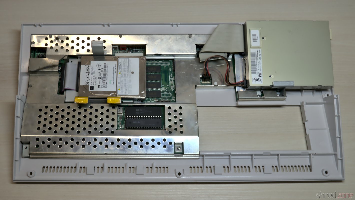
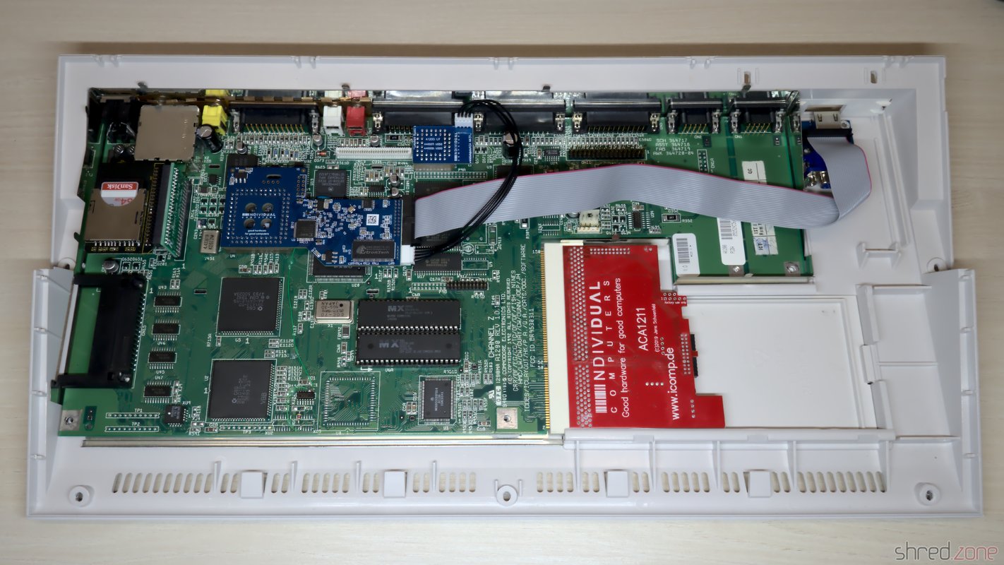
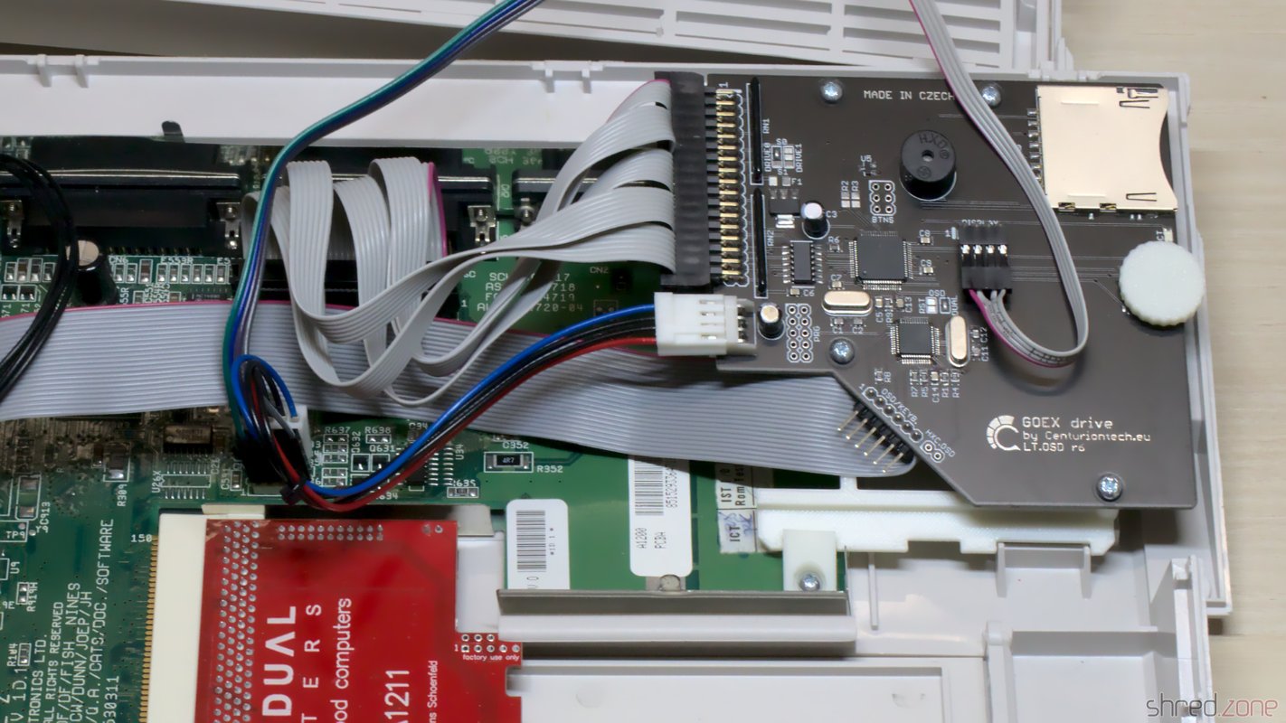
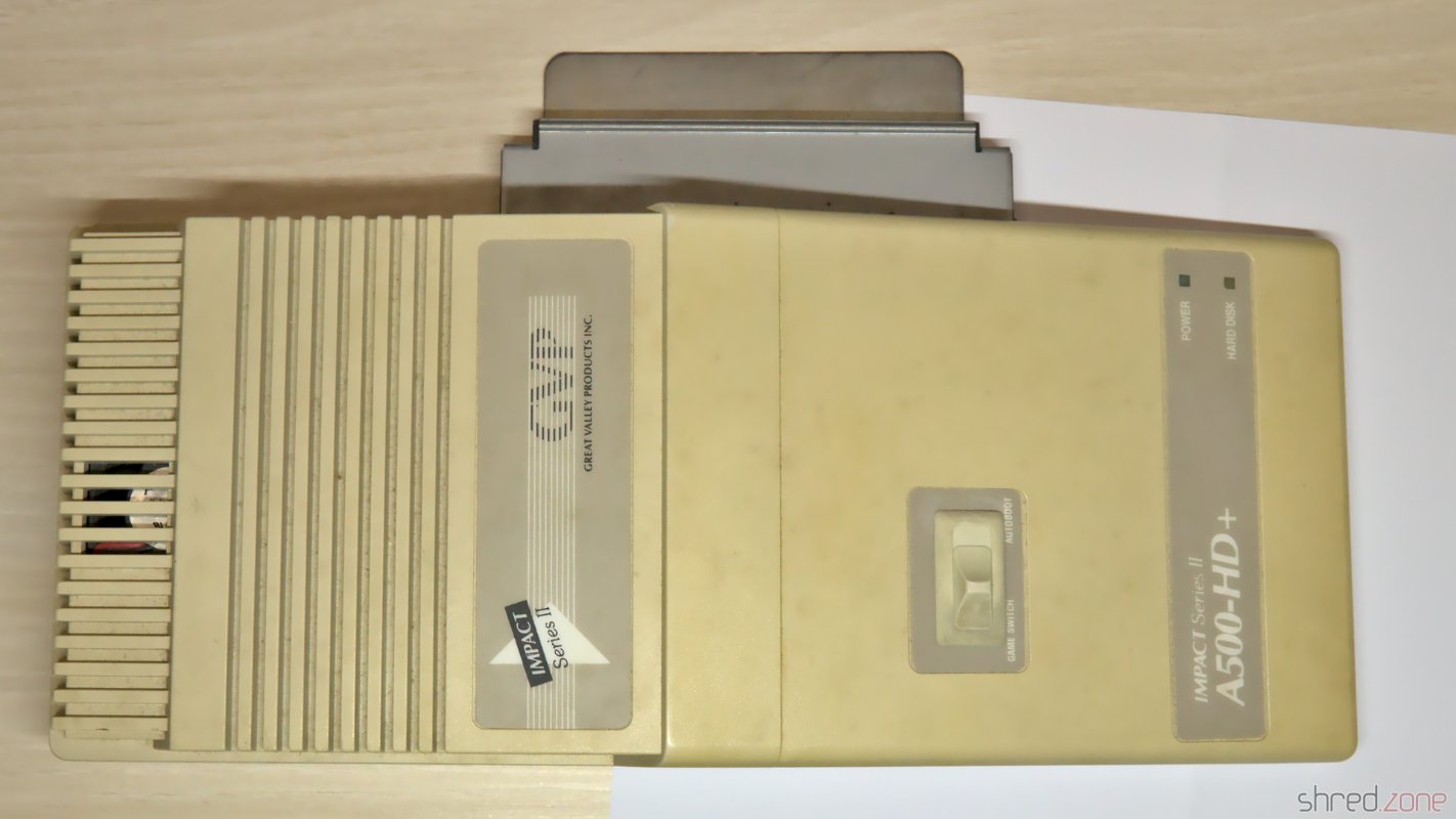
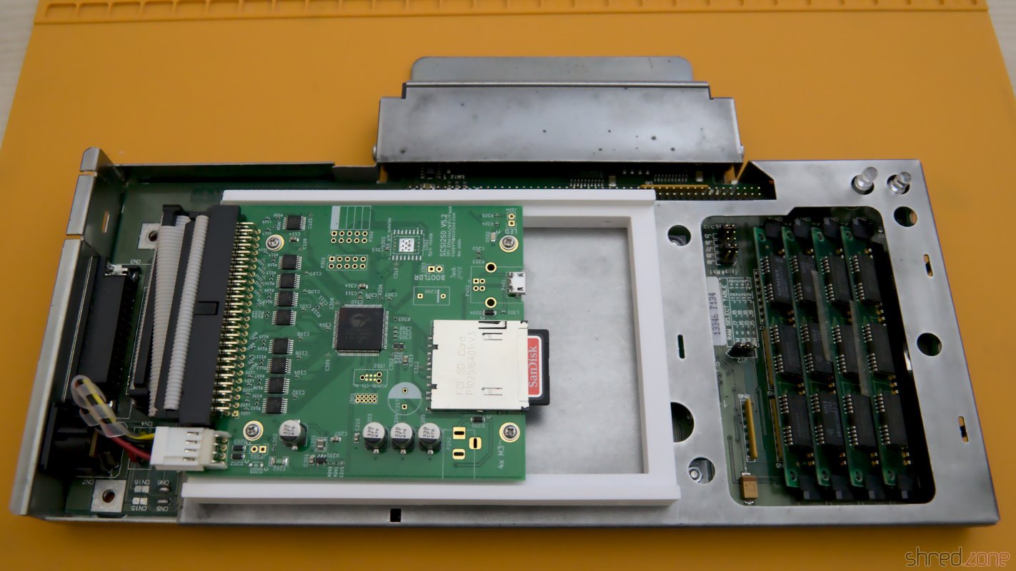
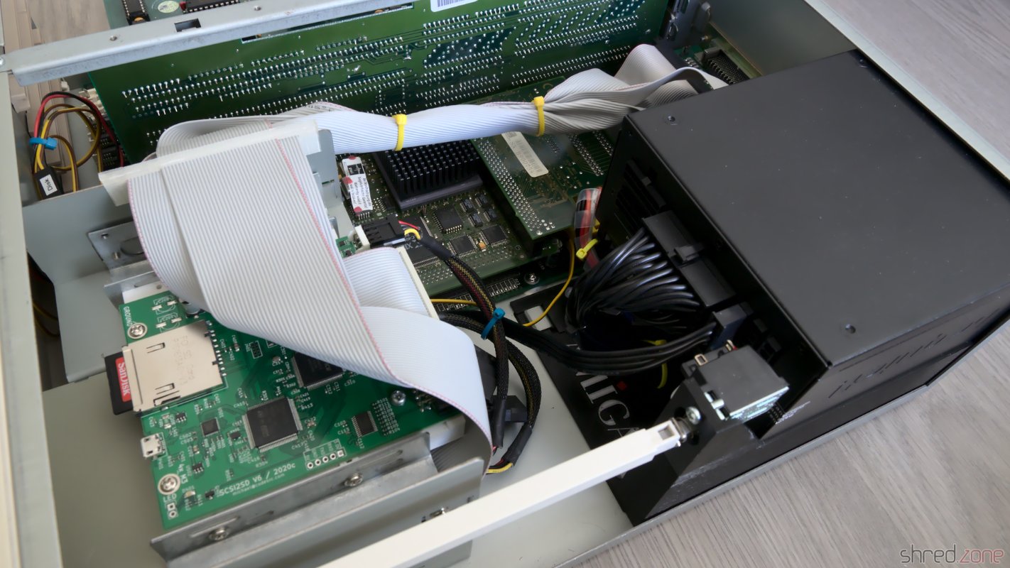
The old mechanical hard disks were loud, slow, and produced a lot of heat. Since I want my Amiga to be as silent (and modern) as possible, I decided to use a SCSI2SD hard drive emulator instead. Alternatively, an IDE to Compact Flash adapter can be connected to the internal IDE header.

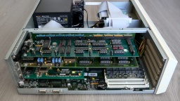
Besides that, I only left a floppy disk drive in the drive cage, but maybe I'm going to replace it with a Gotek floppy drive emulator later. The minimalistic equipment and the modular design of the PSU gives a clean and tidy look on this side of the case. It is also good for the ventilation.

Everything is wired back together. Only one of the PSU's three drive power connectors is accessible, but that's sufficient.

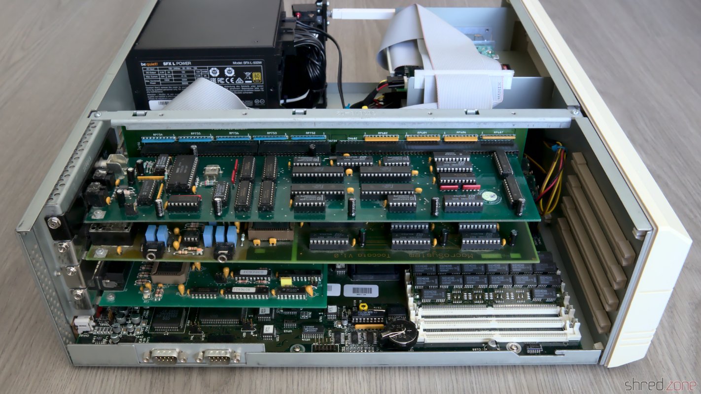
On the other side, the freshly recapped MaestroPro and Toccata sound boards have already moved back to their Zorro slots.

From top to bottom: MaestroPro, Toccata, Scandoubler. What's still missing is a ZZ9000 for HDMI graphics and Ethernet.

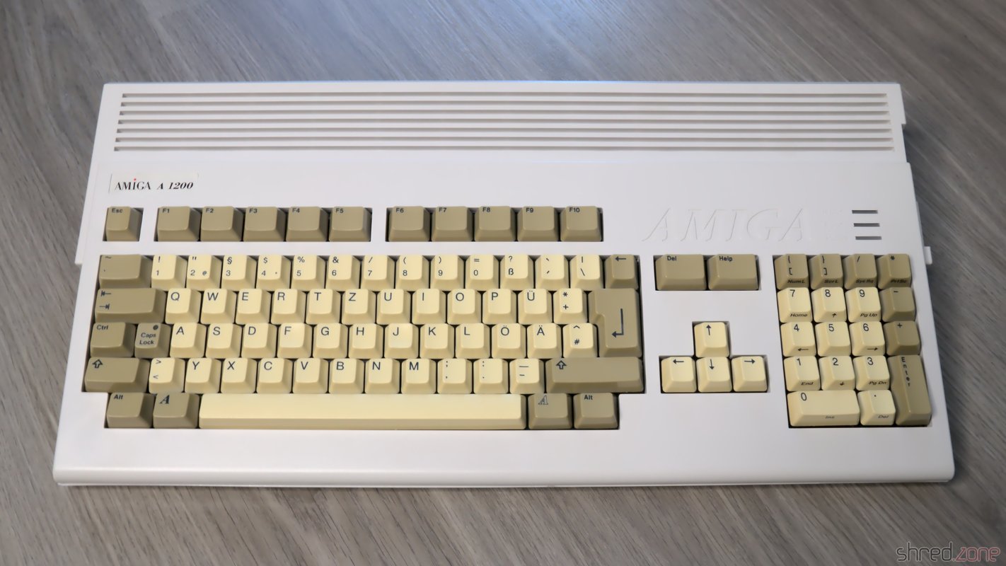
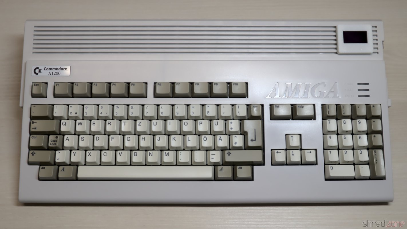
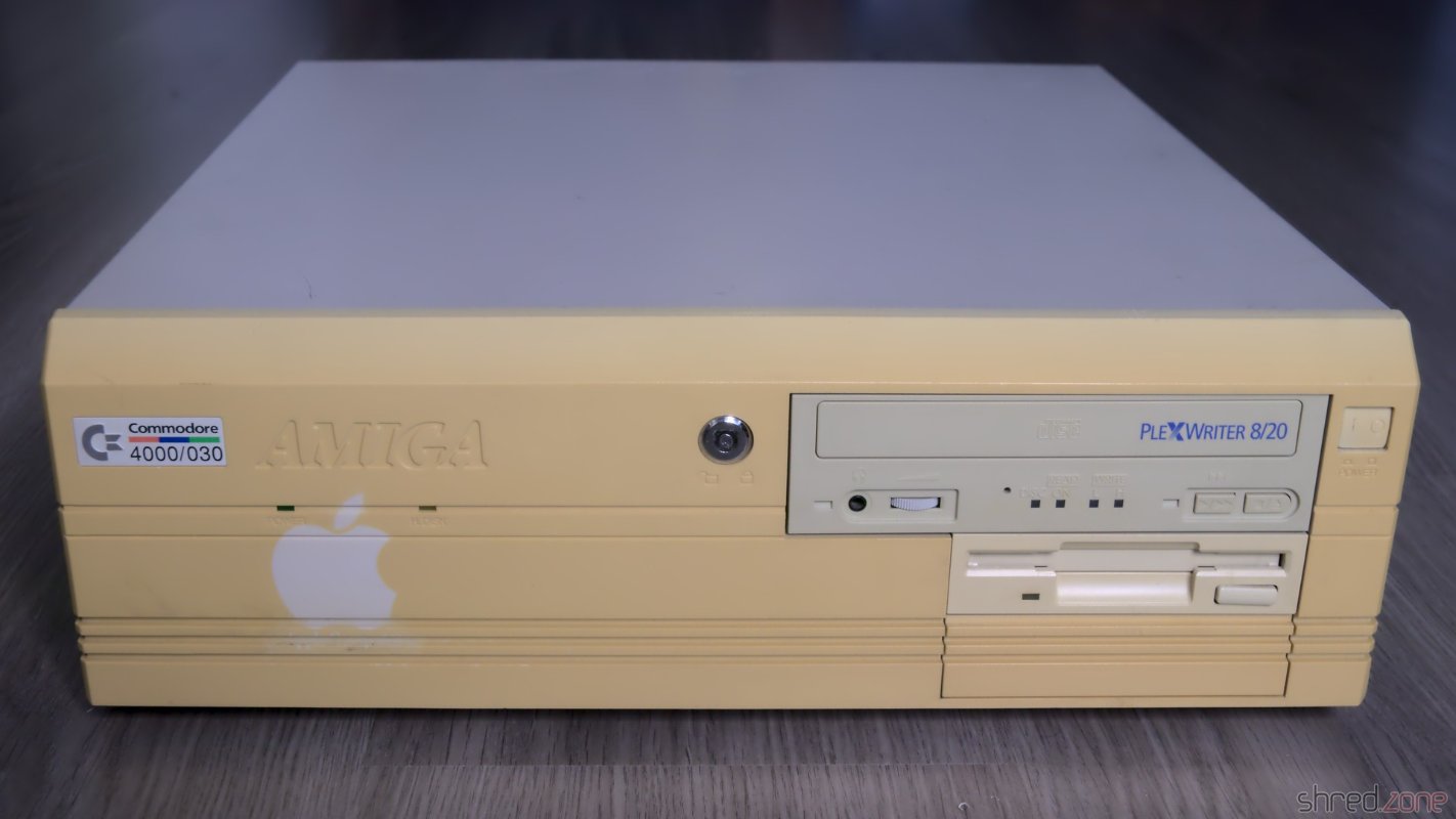
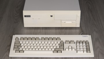
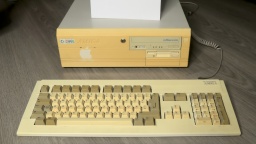
Let's have a look at the outerior. The CBM Museum Wuppertal did an excellent whitening job again. The keyboard looks as good as new, and the outline of the old sticker on the front is almost invisible now. The paint shop did a good work as well, the cover now looks almost brand new.

Isn't she a beauty again? 😍This is how it started. (The sheet of paper is for white balancing.)

I've tried to use my original Workbench installation from the 1990s, which I kept on using in an UAE emulator after that, but it was too messed up and crashed the real Amiga while booting. Finally I gave up and installed a fresh Workbench 3.2 from scratch.

What is still missing is a ZZ9000. It will serve mainly as a HDMI graphics card and Ethernet card. After that, my good old Amiga 4000 is ready for some serious Amiga programming again. πŸ˜‰

Kudos

A refurbishment project like this is not possible without the help of a number of people. First of all, I want to thank the members of the A1K.org Amiga Board, especially halbvier for organizing the rare parts that I needed for the RTC repair. I want to thank the people of the CBM Museum Wuppertal for carefully whitening the plastic parts, and for the nice talk we had. I also want to thank Jan Beta because his YouTube channel inspired me to refurbish my two Amigas.

This project is dedicated to my brother Robert, who had taught me how to solder and how to repair old hardware. I miss you.

More like that?

Read about LinuxJedi's double A4000 restoration.

Amiga 4000 Restauration, Part 1

A few years after I got my Amiga 500, I bought an Amiga 4000 from the pay I got doing my civilian service. At its peak, it was housed in an RBM Big Tower case, and had all kind of expansion cards and an 68060 accelerator board. It was my pride and joy. Later, after Commodore went bankrupt, I switched to Linux systems. My Amiga 4000 was put on a diet and moved back into a desktop case.

The restored Amiga 500 is meant to be used for playing old games and watching demos. In contrast to that, the Amiga 4000 is supposed to become a workstation again. It should be connectable to modern monitors, and should be as silent as possible.

This is the state of the case before restauration.

The "before" photo. The front panel has clearly suffered in the past 30 years.

The computer has suffered a lot in the past decades. The powder coating of the metal cover got a lot of deep scratches from CRT monitors that were placed on it. The plastic front got a deeply yellowed tint. To make things worse, there was a sticker on the front that kept the plastic from yellowing, but now the outline is permanently "burned" into the front instead. The keyboard was in a similar state, although not that badly yellowed.

The CBM Museum Wuppertal already did an excellent job with whitening my Amiga 500, so I decided to also let them whiten the front panel and the keyboard. The experts at the museum warned me that the logo might stay visible after whitening though, but then I could still resort into dying the front black, or even 3D print a new front.

Meanwhile a paint shop is taking care for repainting the metal cover. I decided to keep the original color, RAL 7044 (silk grey).

Let's have a look at the inside now.

Leaked Battery

A true Amiga killer is the NiCd battery that serves as a power backup for the RTC. Sooner or later it leaks and spills battery lye onto the PCB. The lye corrodes the components and traces in its vicinity. If untreated, the board can become irreparably damaged over time. When I first heard about the problem eight years ago, I immediately cut out the battery, but sadly it had already leaked.

The leaked battery, before removal.

For the restauration, I needed to repair this part of the PCB. I generously removed all affected components. Then I neutralized the lye with vinegar essence, rinsed the area with water, then cleaned and dried it with IPA. After that, I used a fiberglass pen to remove the solder mask down to the bare copper, to have an unobstructed look at the damage.

I lost two pads that seemed to be too damaged by the lye. They just came off while I was cleaning the board. Luckily one of them was not connected, and the other one could be replaced with a short piece of wire.

After that I rang all the traces. Three of them were open and also needed to be fixed with a piece of wire. I then used solder to tin the bare copper traces and protect them from corrosion. Finally, I soldered in fresh components.

All affected parts generously removed, and the PCB scrubbed down to the bare copper.The bare copper was tinned to protect it from corrosion. I also had to fix some open traces.Fresh components soldered in. One lost pad was fixed by a wire.

The lye may run to the bottom side through the vias, so it should be checked as well, and repaired if necessary. Luckily I could see no damage on my board.

Since the old rechargeable battery almost killed my Amiga, I decided to use a 3V button cell for backing up the RTC. To prevent the cell from being charged when the power is turned on, I replaced R179 with a standard diode.

Since I removed the crystal and capacitors, the RTC needs a recalibration. I connected pin 17 of the RTC chip (U178) to a scope, and then used a plastic screwdriver to adjust VC190 until the measured frequency was exactly 32768 Hz.

Recapping

Electrolytic capacitors may leak, similar to the battery, and it is recommended to replace all of them with modern premium caps. Some people replace them with ceramic capacitors. They cannot leak, but may have other disadvantages. There are good arguments on both sides, so it's a decision that everyone has to make themself. I decided to order the premium capacitors from my Amiga 4000D Bill of Material list. They are made by Panasonic and have an expected lifetime of up to 10,000 hours, which is maybe the tenfold of the original caps. They are also certified for temperatures of up to 105Β°C, which further extends lifetime.

There are different ways to remove the old electrolytic capacitors. The recommended way is to use two soldering irons, or a hot air rework station. I decided to use a different method that I read about, and twist them off with pincers. It worked surprisingly well, and it took only a few minutes to remove all the caps. To avoid causing damage to the pads, care must be taken that the caps are only slowly twisted, but not pulled from the board.

On the Amiga 4000 the leakage usually starts in the "audio corner", where many SMD caps are concentrated on a small space. I was lucky because all the caps were still intact there. On my board, C317 has leaked though. It was visible by the corroded solder joints around it. When they were heated, there was also a typical telltale smell of microwaved fish. Again, I generously removed the components around the damaged part, cleaned the PCB, and soldered in new parts.

C317 has leaked and corroded the surrounding.All affected parts removed, and the PCB cleaned up.New parts soldered in, with a bit too much solder though. πŸ˜…

There are also a few axial caps on the daughterboard. They usually don't tend to leak as easy as SMD caps, but since we're on it, they should be replaced as well.

When I repared the battery damage, I also had to remove two of the SIMM sockets. The original sockets have plastic brackets that easily snap off, so I decided to finish what I started, and replaced all five sockets with new ones having metal brackets.

In a final step, I washed the board with IPA. It was then repaired, cleaned, and ready to be put back into the computer case.

The restaured mainboard. It won't win a beauty contest any more, but I hope it is working again.

In the next part I will take care of the power supply, and I will put the system back together.