After the test run was successful in the previous part, it's now time to put my Amiga back together.
Whitening
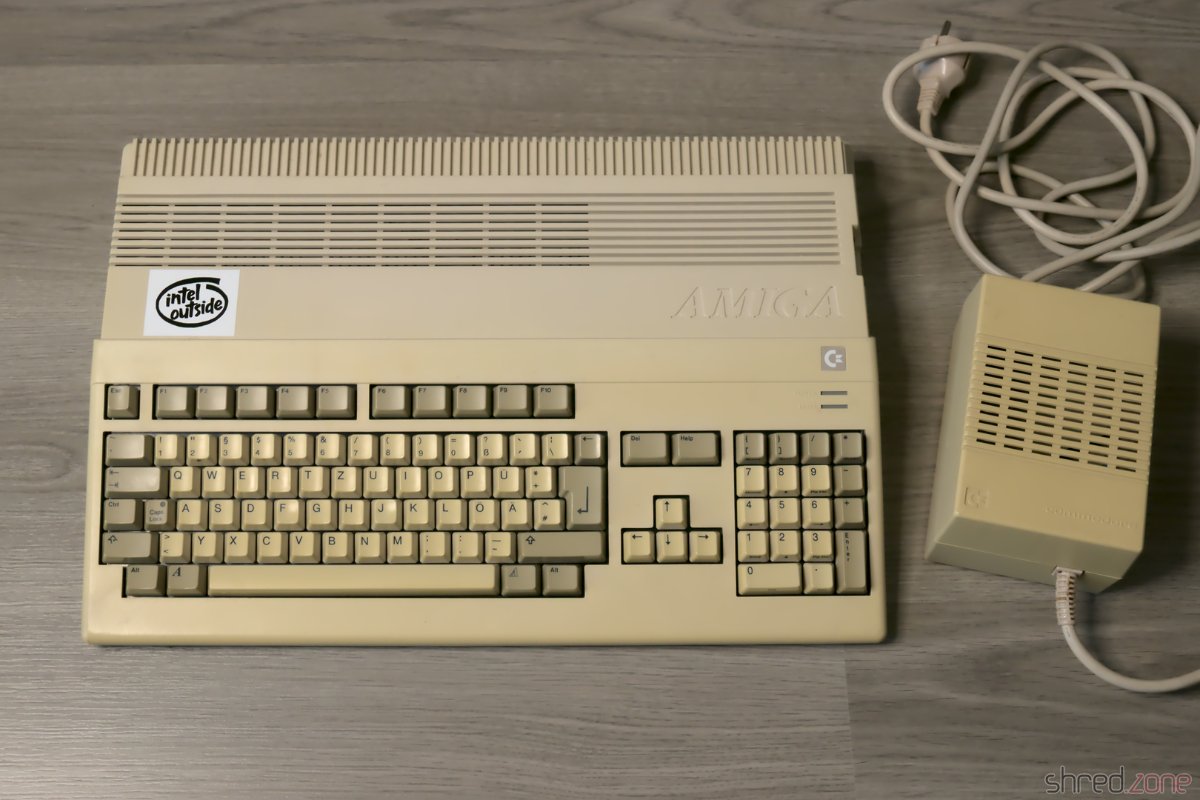
I've got the case parts and keycaps back from whitening at the CBM Museum Wuppertal. And the mandatory before-after photos proove that they did a great job:
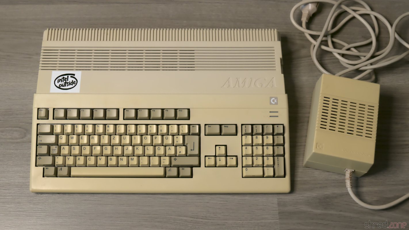
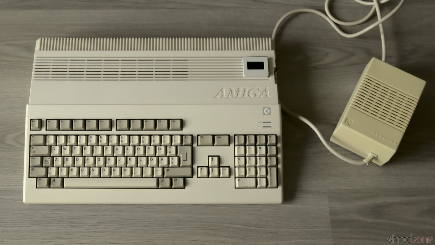
Sadly the PSU case is made of a cheaper material, and could not be whitened any further without risking the dreadened "marbling", so it stills look a bit yellowed. (I forgot to use a ring light for the photos, but I did my best to make both pictures comparable.)
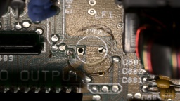
Removing the Rust
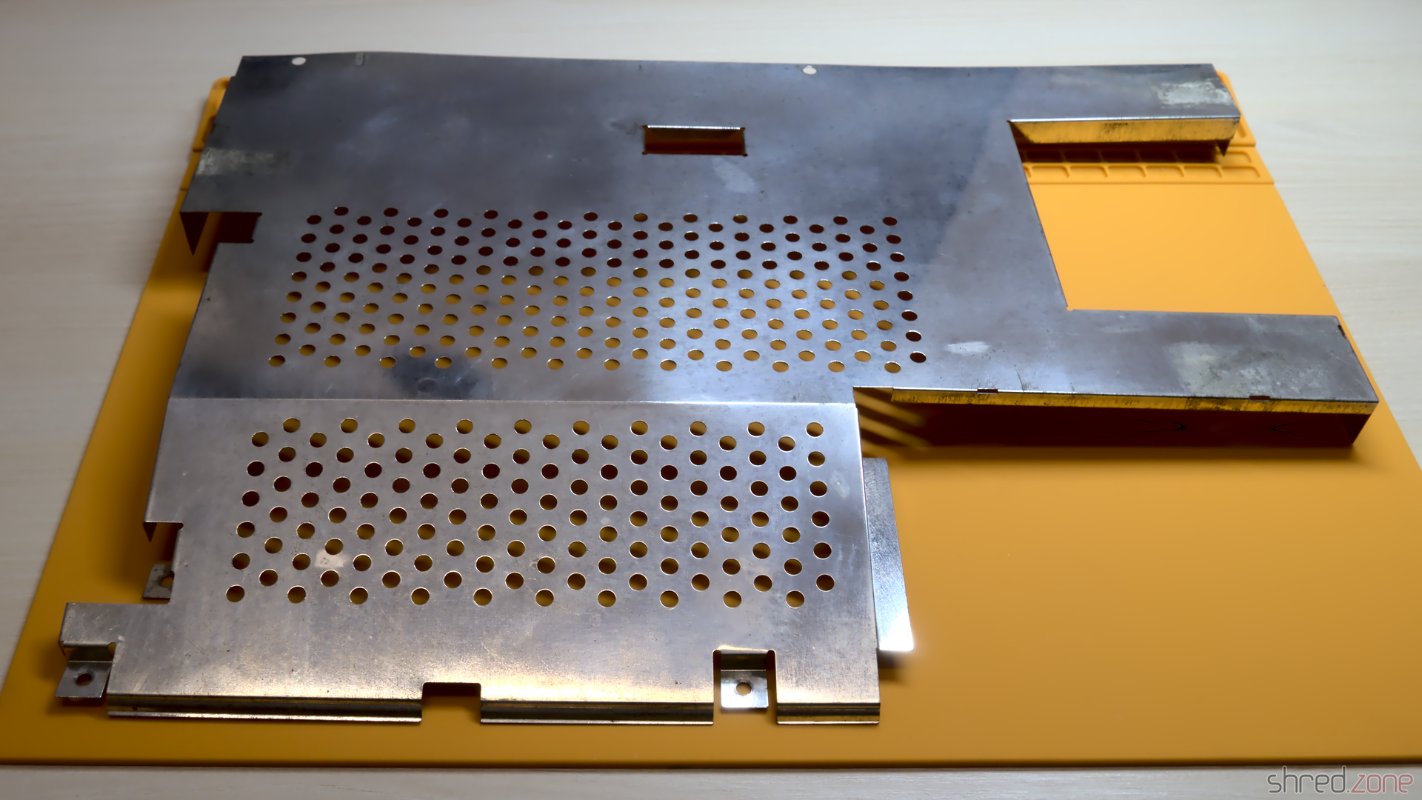
Due to my careless storage in the cellar, the metal shielding got a bit of rust over the years. I removed the worst rust spots with a fiberglass pen. Then I polished the shields with Nevr-Dull wadding polish, which removed a lot of the rust film. The result is still far from perfect, but it's hard to impossible to restore the original look of the shielding, so I decided to keep it that way.
PSU
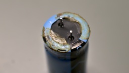
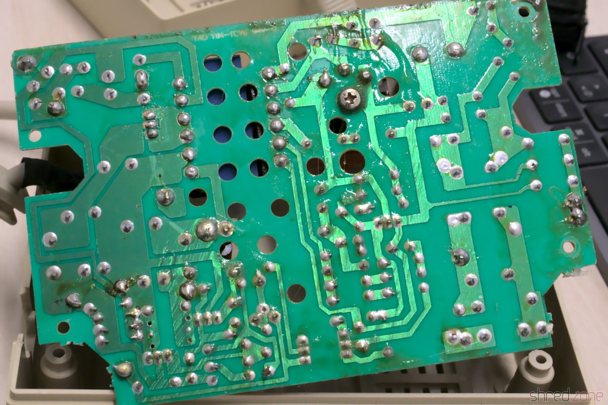
I have already prepared the PSU in in the last part. Now that I also got the PSU case back, it's time to put it together. I've first replaced the power switch, as the old one got broken over the years. Luckily it's a standard switch that can still be found at electronic shops.
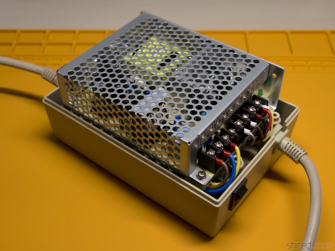
The Mean Well RT-65B fits into the case surprisingly well, almost as if it was made for it. I only had some difficulties to find a proper position for the wires. I tried different positions, and also tried to switch the sides of the mains and Amiga power cables.
The best result seems to be the original orientation of the cables (mains cable at the side of the power switch). With a bit of tweaking, I could finally route all the wires properly, make the RT-65B fit in, and close the PSU case.
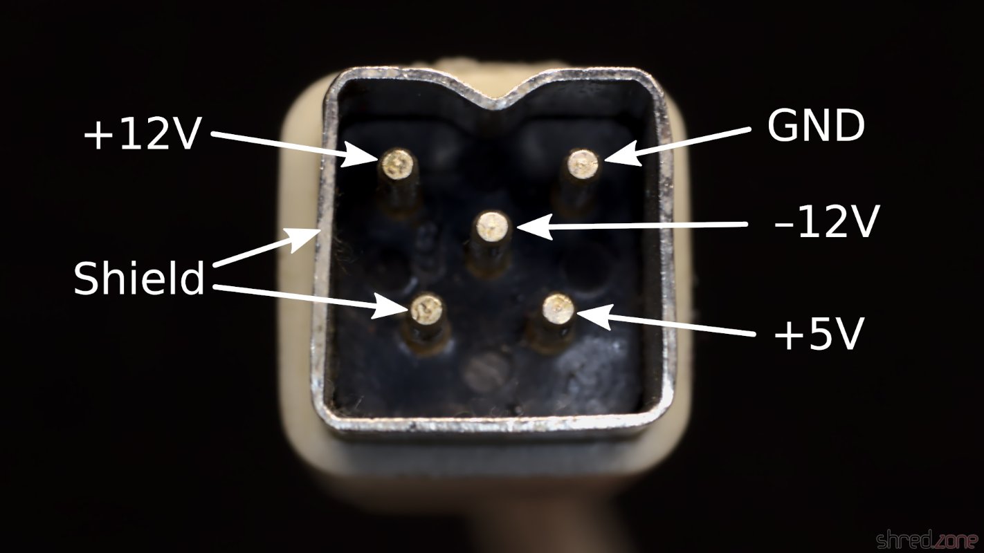
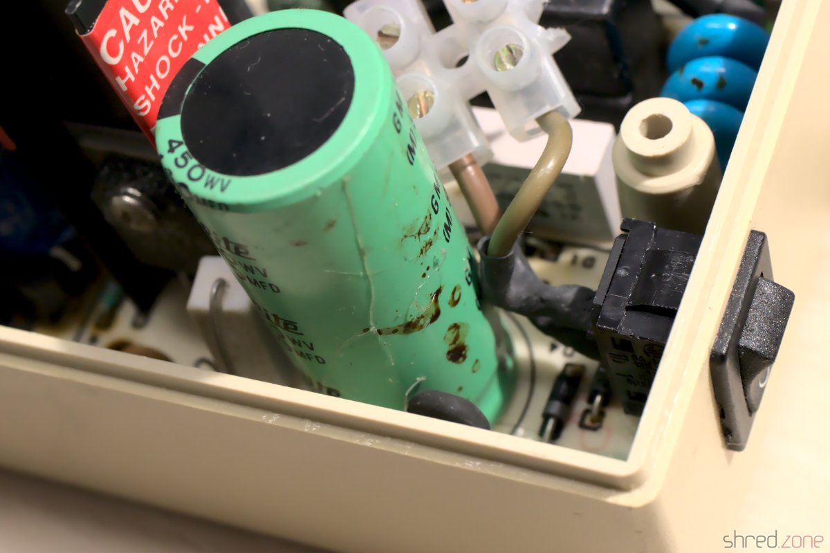
I recommend to check the correct wiring (especially of the earthing) and the voltages once again. Also make sure that the terminals are firmly closed, and that no wires are overly bent, squeezed, or punctured.
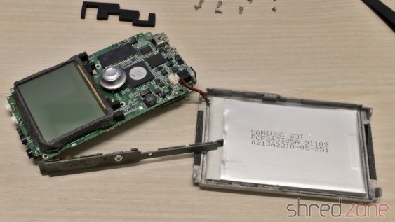
GOEX Drive
The GOEX drive optionally comes with an OLED display that sits on top of the Amiga case and shows the currently selected file, and the current disk track. I can really recommend to order that display with the drive, as it makes selecting a file a lot easier. Unless of course you use the "GOEX on pills" version that offers a disk menu on the screen as OSD, but I wasn't sure how this version would interfere with the RGB-to-HDMI converter I am using.
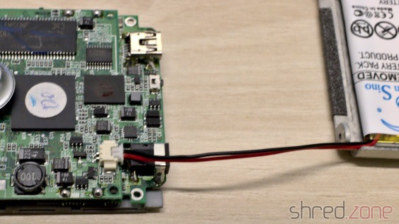
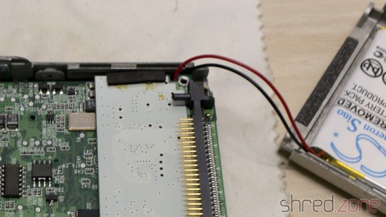
The display is readily assembled, and already has crimp connectors at the end of the cable. The idea was to push them through an opening of the ventilation grille, but they just were too big for that. I had to cut them off, push the ribbon cable through an opening, and then solder new connectors to the cable.
HDMI Connector
Next problem was the HDMI connector. I use c0pperdragon's RGB-to-HDMI converter to connect my Amiga to a TV or monitor via HDMI. But where should I put the HDMI connector so I can reach it from the outside of the case?
My original idea was to cut a matching hole into the back of the Amiga case, but later I dismissed the plan and decided against disfiguring the case even further than I already did in the 1990s. A better idea was to print an expansion port cover with a hole for a HDMI cable, even though I disliked the thought that a cable would then loosely hang out of the case.
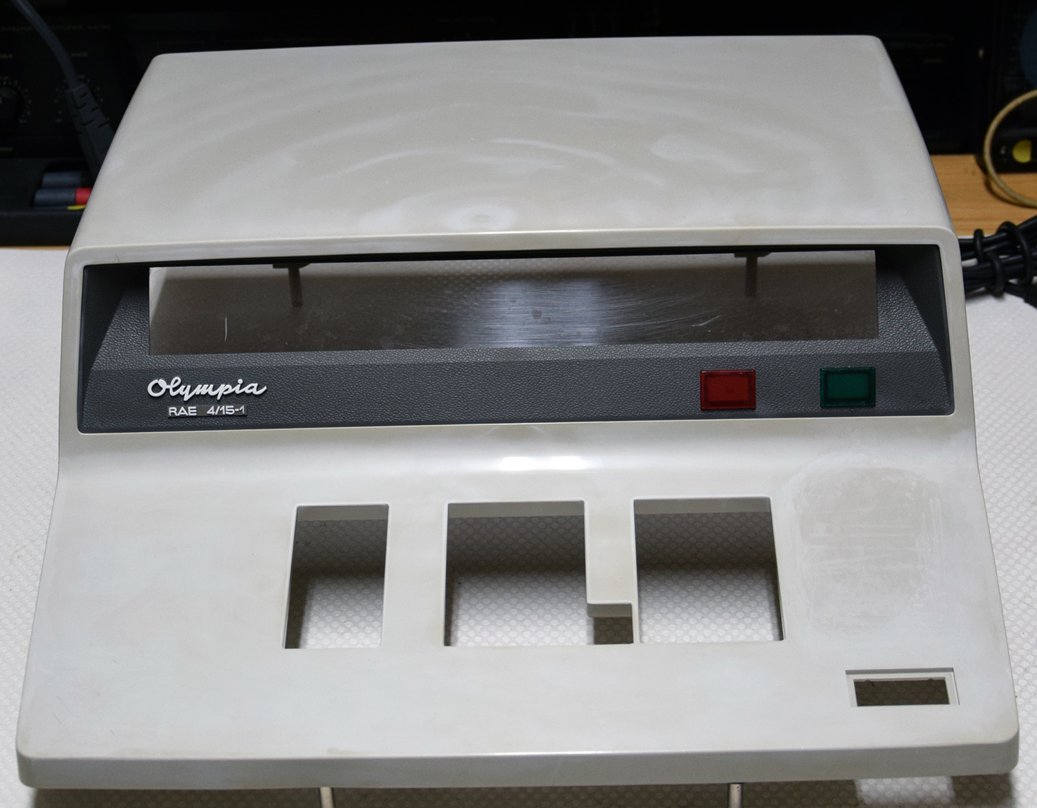
Then I noticed that the GOEX drive left a hole where the floppy drive's eject button has once been. And this hole is actually big enough for a HDMI connector, almost as if it has always been meant for that purpose.

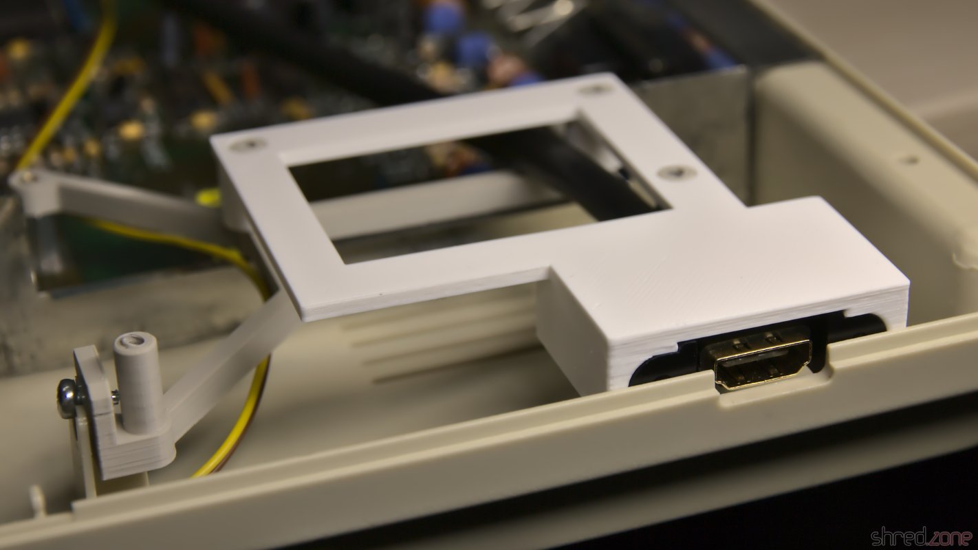
I designed a 3D printed frame that holds the connector of a Delock 85463 panel-mount HDMI connector. You can find the STL file at Printables for reprinting.
It looks a bit weird when a HDMI cable is plugged into that place where once the disk eject button has been, but it is working amazingly well, and saved me from cutting further holes into the Amiga case.
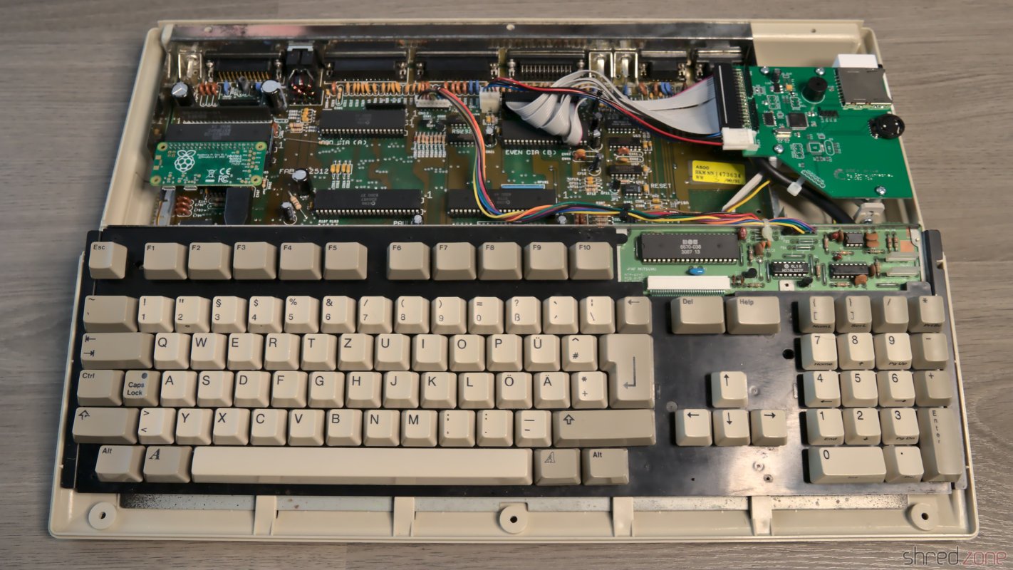
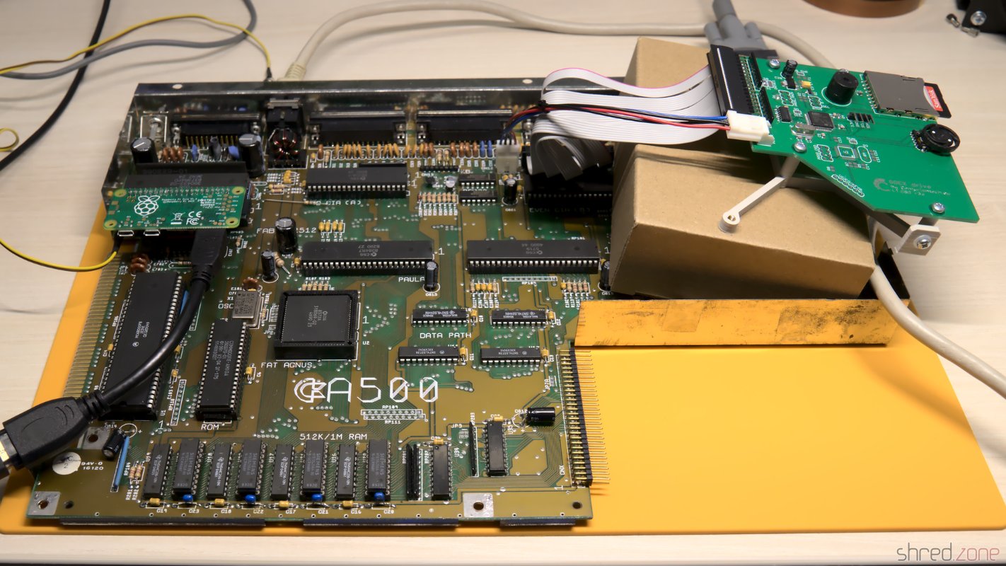
Completed
Now everything was mounted in its place. I couldn't close the upper shielding though, because the HDMI converter is in the way, so I decided to leave it out.
And that concludes the restauration project. Welcome back, Amiga 500. With this hardware upgrade, you should be fit for at least the next decade.

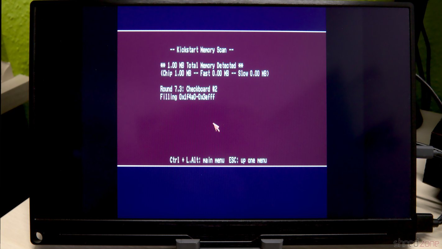
The Kickstart Dilemma
Well, not quite. There is a Kickstart 2.04 ROM installed in this Amiga, and while playing some old games, I found out that a surprisingly large number of them crash on that version of the AmigaOS. It was indeed a big problem of the Amiga back in these days. In the previous generation of home computers, the operating system was static and was never updated, so programmers assumed to find certain routines at fixed positions. When the Amiga got popular, programmers continued to use the operating system like that, ignoring documented rules. Then in 1990, Commodore released Kickstart 2.0, a major AmigaOS upgrade. And suddenly, many poorly programmed games crashed, but instead of the programmers, the Amiga was blamed for it.
I still have an original Kickstart 1.3 ROM here, along with a ROM switch. Maybe I will use that board again. Luckily, I haven't yet closed the holes that I once drilled into the case, so I can use one for the switch again.


