 The Teenage Engineering OP-1 is a portable synthesizer and sound recording system. I got one in 2016 because I was fascinated by its abilities that were shown in many YouTube videos. But to be honest, my musical talent is limited, and so it became more of a toy that was finally stowed away in a cupboard for several months.
When I took it out again, I found the battery deeply discharged. Considering the age of the battery, I decided not to charge it again, because there is a risk that it would swell and damage the OP-1. Instead my plan was to remove the battery and use the OP-1 without it, since I don't make use of its mobility anyway. It would then need to be connected to USB power for using it, but that would be absolutely fine for me.
I also found reports of people where the battery did not charge anymore, or was already depleted after a couple of minutes. There are many reasons for a battery change.
Note that this article is about the classic OP-1, not about its successor, the OP-1 field.
Removing the Old Battery
CAUTION: Be very careful when handling LiPo batteries! Do not use sharp blades or pointed tools to remove the old battery. Never use force and avoid physical damage. Never short circuit the battery! Make sure that the terminals of the battery cables cannot accidentally touch each other. If you notice any swelling or unusual heat, stop using the battery immediately. Dispose of batteries properly, following local regulations.
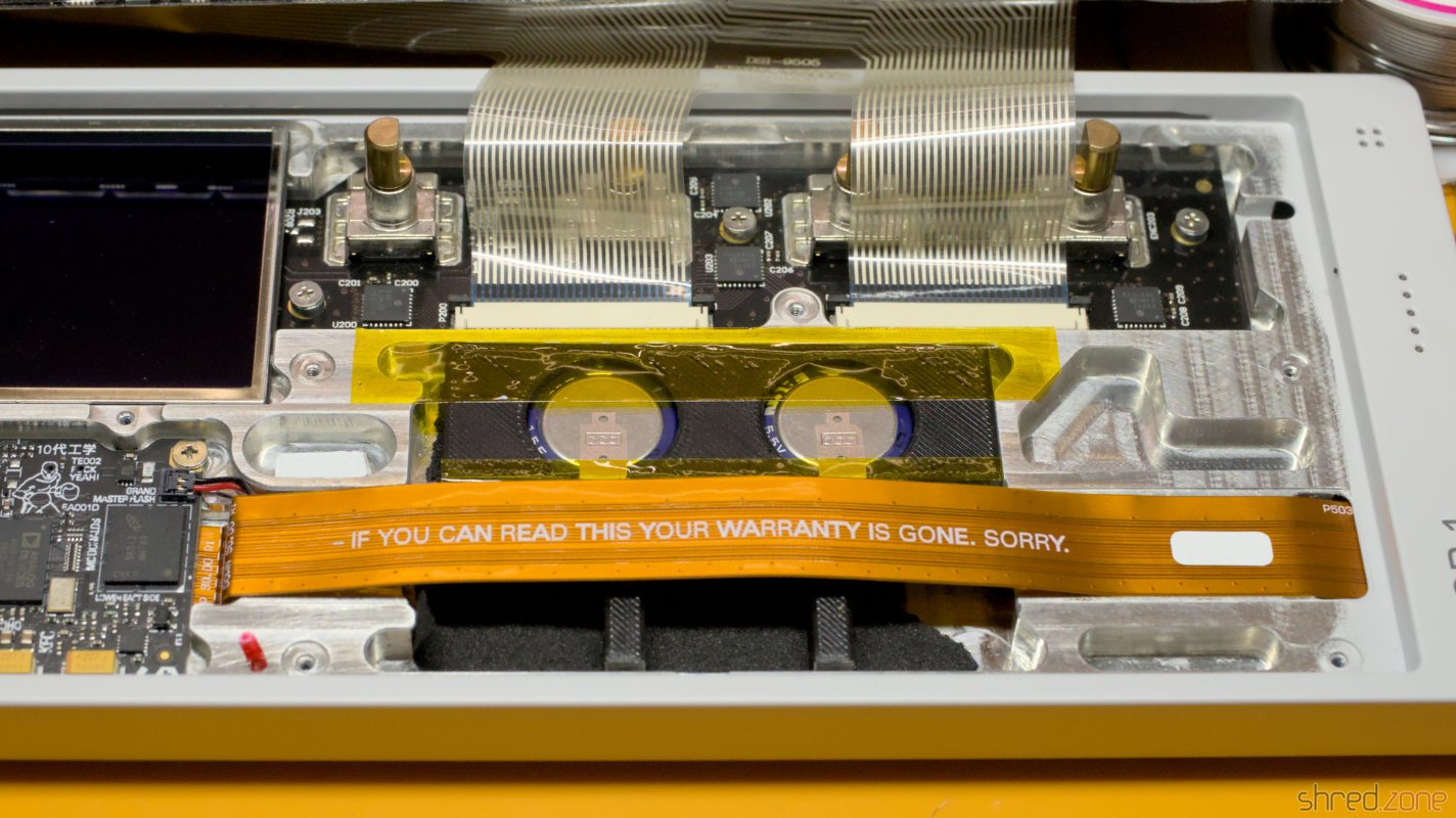
If you should still have a warranty on the device (for any reason), it will be voided with the procedure.
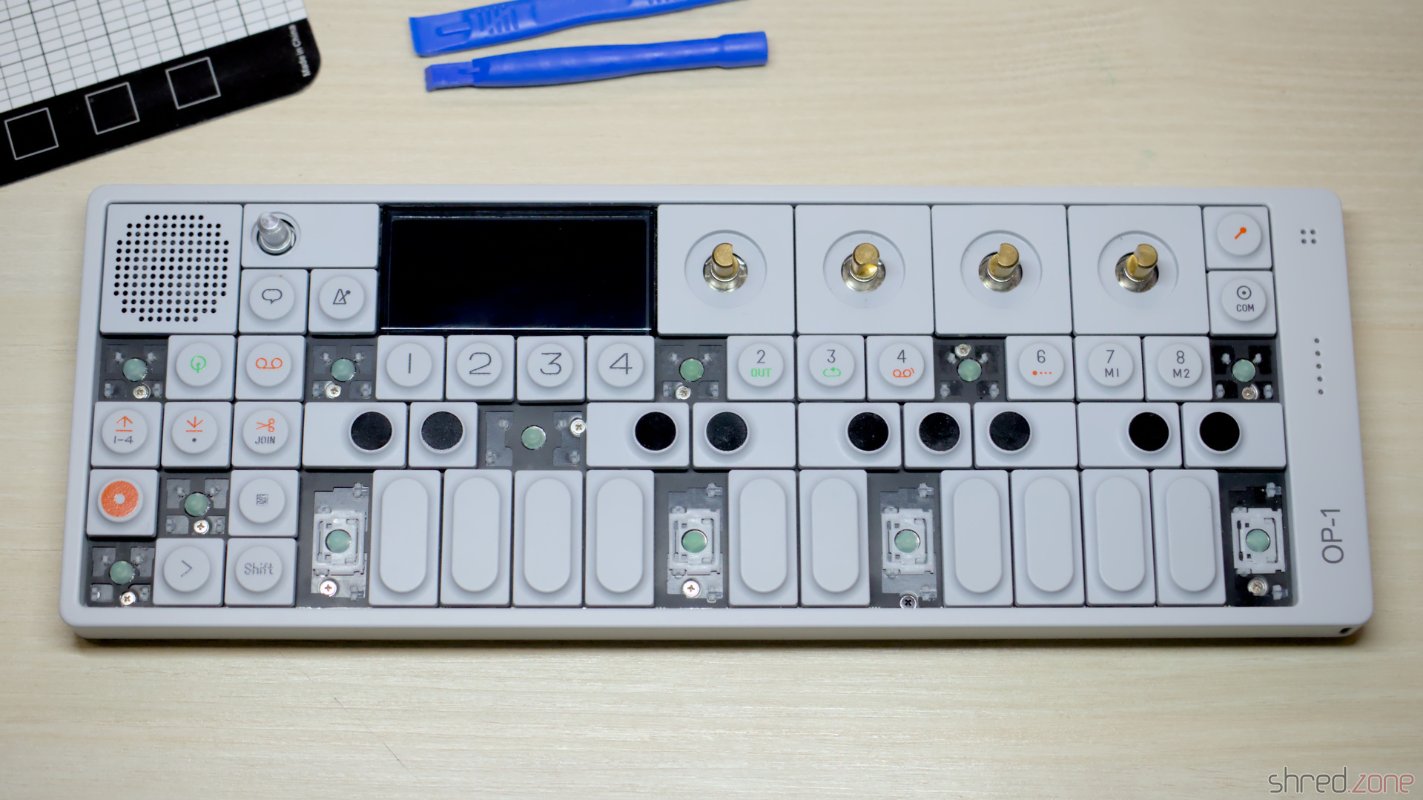
There is a good guide at iFixit about how to open the OP-1 and remove the battery. To do so, you need to remove the back panel and a couple of the keys that hide the case screws.
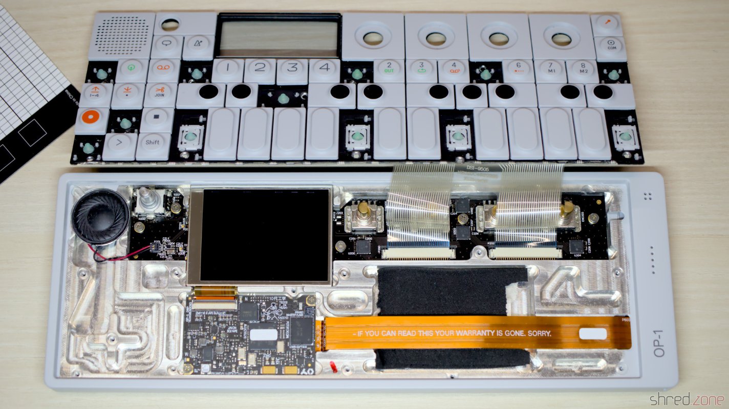
On my OP-1, I found out that it wasn't necessary to remove the back panel. The battery was only lightly glued to the case, and I could carefully remove it with the connector ribbon cable still in place.


The battery connector needs to be lifted up, not pulled to the side. Although I was careful, I broke the terminals out of the connector's housing. It was okay for me, since I intended to use the OP-1 without battery anyway.
However, my plan failed…
The Disappointment
After I removed the battery, I powered the OP-1 via USB, and turned it on. Unfortunately it crashed after a few seconds.

I later found out that the OP-1 works without battery when plugged into a USB charger, but it crashes almost immediately when plugged into the USB port of a PC. Since this is the only way to access the file system of the OP-1, running it without a battery does not seem to work.
Well then, let's order a new one and get the OP-1 fixed properly. It's a LiPo 055070 (aka 505070) battery with 3.7V and a capacity of 1800mAh. In case you also broke the housing of the power connector: it's a Molex Pico-EZmate receptacle crimp housing, 1.2mm pitch, 2 circuits (part number 781720002).
A New Battery?
And here comes the next disappointment.
Teenage Engineering refers to iFixit as spare part vendor. However, iFixit does not sell these batteries in Germany, and they seem to be out of stock in other countries.
Then I asked the manufacturer for help. They answered that they had no replacement batteries for the OP-1 in stock, and that they don't know when or if they would ever be in stock again. Their suggestion was to keep using the original battery.
I searched the internet and asked retailers for replacement batteries, but to no avail. So I was stuck. The OP-1 wouldn't work without batteries, and a new fitting battery was nowhere to be found. Would I have to throw away my OP-1 which is still looking almost pristine?
Going Batteryless
The simple answer is: No. I could use any other LiPo battery with 3.7V and similar, smaller dimensions. It would have a smaller capacity, and would need to be charged more often, but otherwise it would be okay.
However, my original goal was to use the OP-1 without any battery. I would have to find a way to make it run when connected to a PC.
I started an experiment. Instead of a battery, I used an electrolytic capacitor. The first one I found in my tinkering box was a 470µF 35V type, and I connected it to the battery connector with alligator clips.
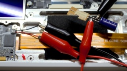
A first test showed that it fixed the crash, and the OP-1 now even started when connected to the PC. However, when I tried to establish an USB connection for transporting files, it now immediately shut down.
I tried the biggest capacitor I could find in my box, which had 4700µF 16V. This time, the OP-1 did not crash anymore no matter how hard I tried. Unfortunately, the 4700µF capacitor is far too big to fit into the OP-1 case.
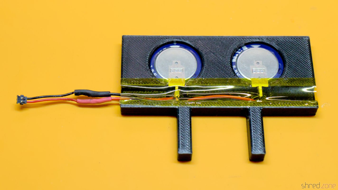
What fits perfectly though are coin cell supercapacitors. I ordered two Eaton KR-5R5V155-R EDLCs (1.5F, 5.5V), but basically any supercapacitor can be used that is not higher than 5mm and is rated for voltages of 3.7V or more. Also, one supercapacitor would be sufficient as it would still exceed the capacity of my test capacitor (4700µF = 0.0047F) by far.
My tests with the supercapacitors were very promising. When I used both of them, the OP-1 was still working for about three seconds after being disconnected from USB.
WARNING: Using supercapacitors instead of batteries is experimental. If in doubt, always replace your old battery with a new LiPo battery!
Never perform firmware upgrades after this modification! It is possible that the device relies on sufficient battery power during the upgrade process. Your device could become bricked!
Also remember to always turn off your OP-1 before disconnecting from power, to avoid data loss and file system corruption.
I 3D-printed a frame for the capacitors and put it into the space of the original battery. Since the case is made from milled aluminum, it is important to take care for proper insulation! The bottom side of my frame is solid for that reason.


And that's it! Now I have a batteryless OP-1. Even though it needs to be permanently connected to a USB power source now, I never have to worry about old or deeply discharged LiPo batteries again.
What I've Learned
To be honest, I was very disappointed with Teenage Engineering. The OP-1 was an expensive item. It's ok for me if the manufacturer doesn't offer warranty after this long. It's also fine if they don't have spare parts in stock after almost 10 years.
Still, I wish they had a better solution to offer than just suggesting that I keep using the original battery, even at the risk of swelling (which would ruin the case and be a potential fire hazard). In essence, they were telling me to throw away a machine that was otherwise still good.
Fun Fact
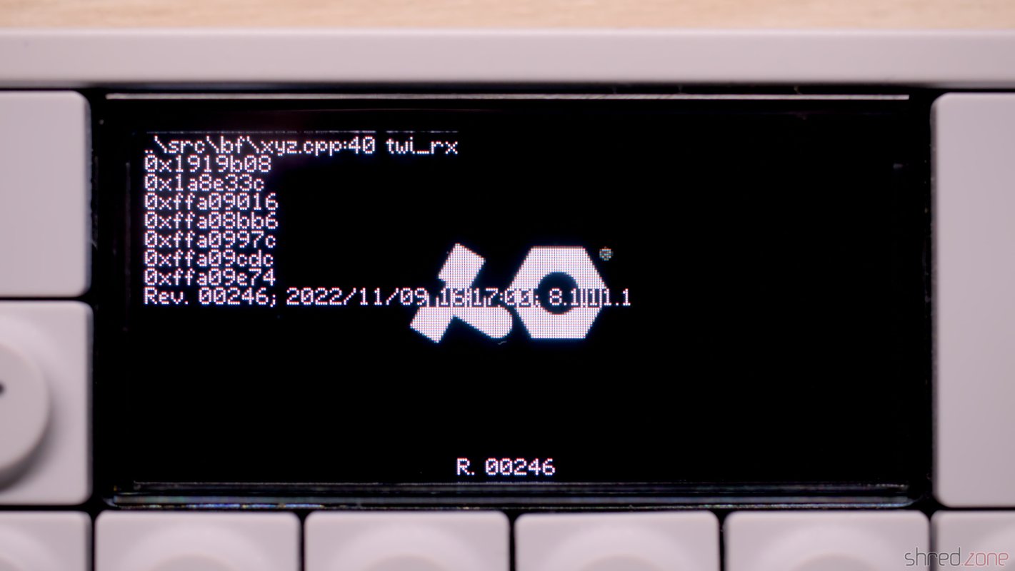
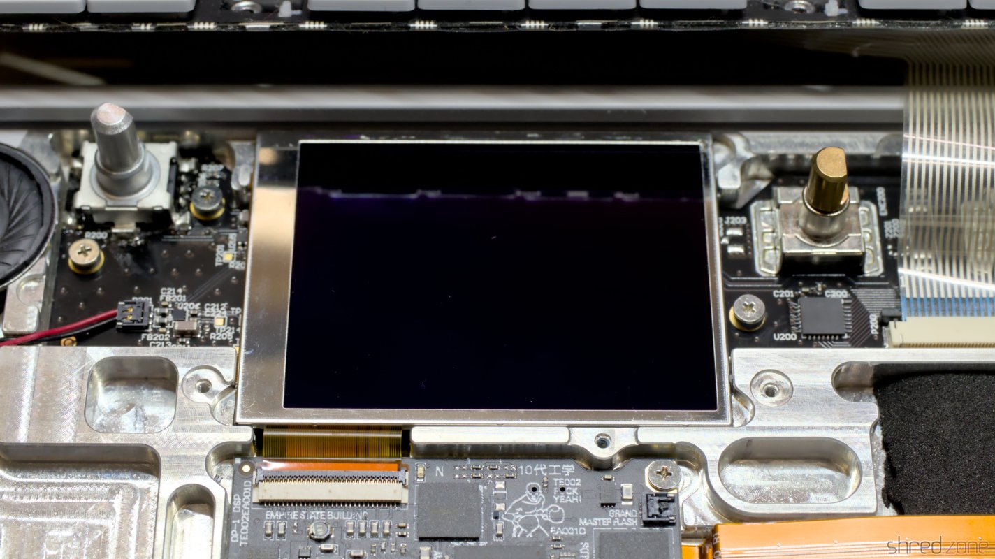
By the way… Did you know that the actual display of the OP-1 is much larger than the window of the case? About the bottom third of the OLED display is unused.

 I have migrated all my source codes from GitHub to Codeberg.