Inari figures

#Restauration

Amiga 500 Restauration, Part 1

My first Amiga was an Amiga 500. A classmate already had one, and when I visited him and saw the Amiga for the first time, I just had to have my own. So I pestered my parents until they gave in and bought one for me. With this computer I learned 68000 assembler, programming in general, and blind ten-finger typing.

A few years later, I bought an Amiga 4000 from the pay I got doing my civilian service. My good old Amiga 500 spent a few grace months in a closet, and was then stowed away in a box in the basement, forgotten for about three decades.

I would like to restore this machine, make it beautiful again, and give it a subtle technical overhaul. This project is a work in progress. I will report in my blog whenever there is something new. And in the end, I can hopefully share a feeling of success with you.

These are my goals for the restauration project:

  • The case has likely got a yellow tint over the years, like all white computer cases of that era. The yellowing has to go, the case should look as good as new again.
  • I will give it a technical overhaul. The electrolytic capacitors may have leaked and will be replaced. But after all the years, there may be even more technical problems that need to be fixed.
  • Since I have almost no floppy disks left, the floppy drive will be replaced by a drive simulator.
  • The old 1084 CRT monitor is long broken and disposed of (I hated these old flicker boxes anyway). I want to connect the Amiga to a modern TV instead, preferably via HDMI, so I will have a closer look at this Raspberry Pi Zero based converter that will be connected to the Denise socket.

After the restauration, the Amiga should feel (more or less) like it did when I once got it. This means that there will be no accelerator card or harddisk controller. Apart from the HDMI output and the floppy simulator, the only acceptable "tuning" is the chip RAM extension to 1 MByte.

Okay, so let's get the computer out of the box and have a first look at it:

My Amiga 500 before restauration.

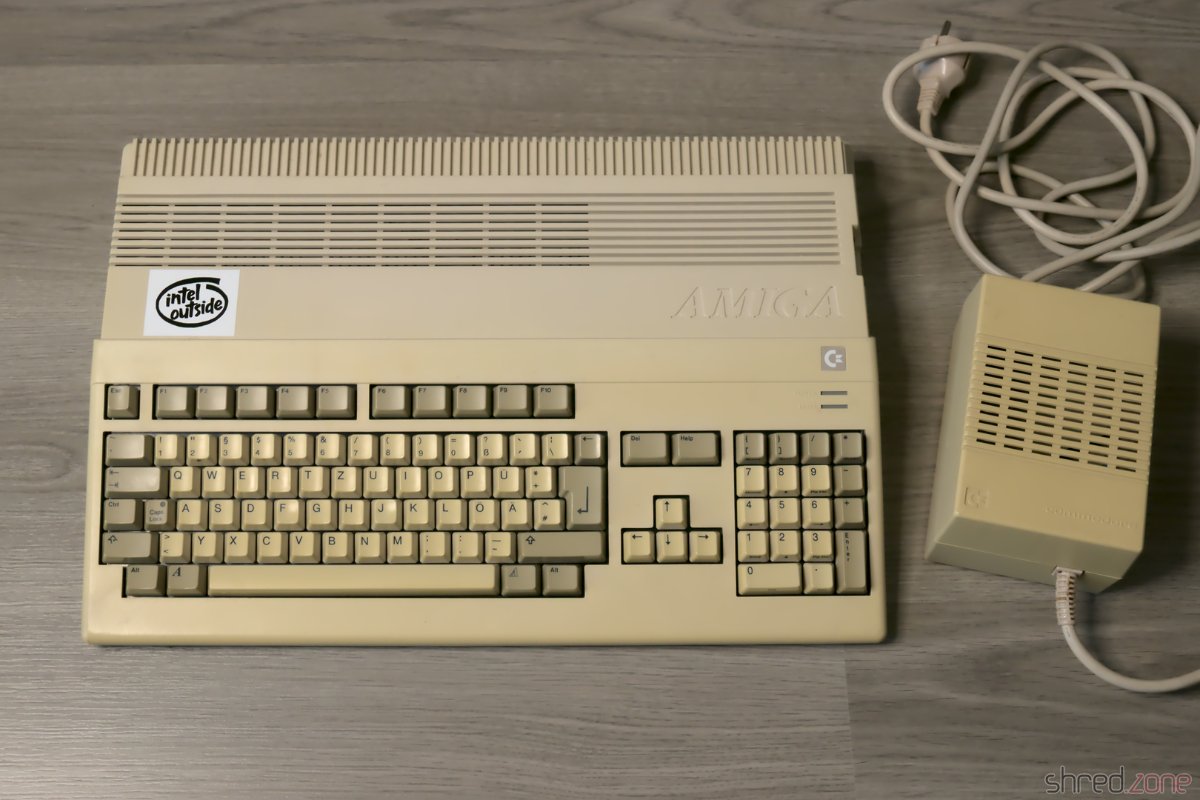
The case is not quite as yellowed as I had feared, nevertheless the ugly "nicotine yellow" has to go. On the right side of the case I had added four switches. At that time the Amiga was rather a commodity, and I didn't care much about it. Today I scolded my old self for drilling holes into that beautiful case. So there's one more item on my to-do list: fill the holes.

As for the case, I couldn't decide if I should have it dyed black, or have it bleached at the CBM Museum Wuppertal (CMW). I couldn't find a paint shop who would dye plastic though (they only offered varnishing), and the contact to the CMW turned out to be nice, so the case will now be bleached by the professionals there.

I have to admit: My fingers were itching to plug the Amiga into the wall socket and the TV right away. Fortunately I didn't do that. The circuit board of the power supply looks like it has been soaked in coke:

There is some dried liquid all over the PCB.

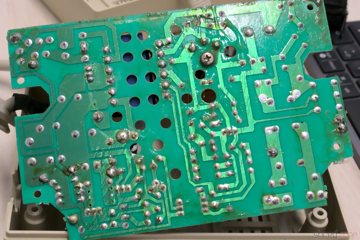
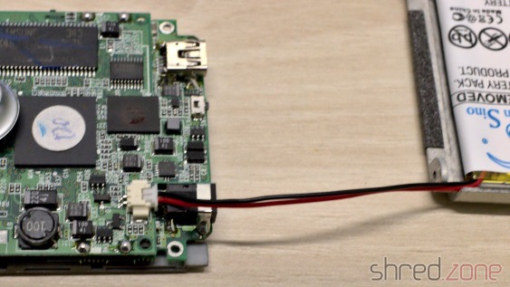
There are no traces of that liquid inside the case, so my guess is a leaked capacitor. Maybe it was this one:

There are also traces of liquid on this capacitor.

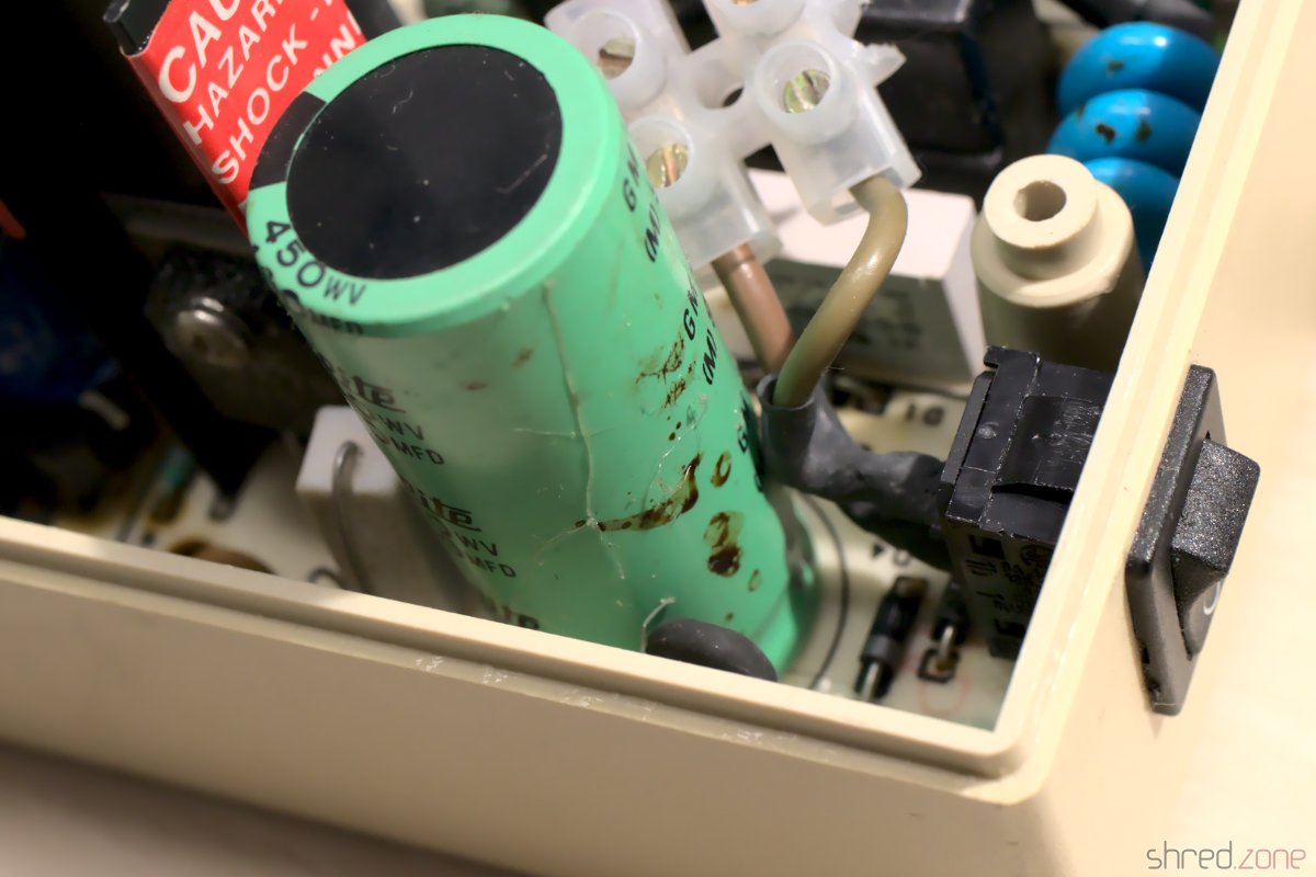
A homemade repair is totally out of the question if mains voltage is involved. Modern switching power supply modules are simply too cheap for that. So the next item on my to-do list is: get a new power supply.

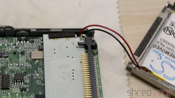
Let's have a look inside the Amiga. The metal cage is a bit rusty here and there, but all in all still in good shape. The circuit board smells a bit of cellar mustiness, but everything is in its place and nothing seems to be damaged. It all certainly does look very good!

The mainboard looks good. The self-made PCB is for an NMI button and is connected to the IRQ lines of the CPU.

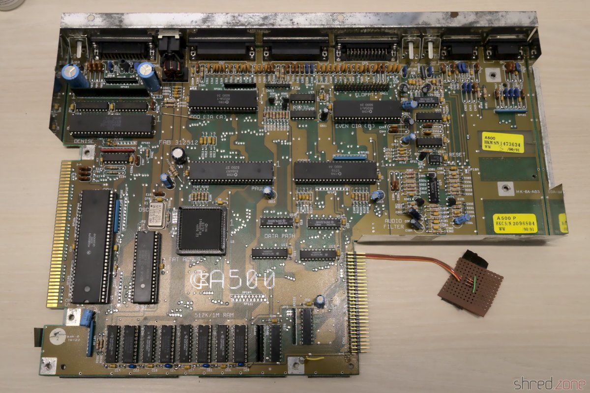
For recapping I inspected all the electrolytic capacitors and listed their values. After that I found out that someone else did that work already. I will replace all the capacitors with premium ones, which sounds more dramatic than it is for cent items. I chose Panasonic caps with a lifetime of up to 10,000 h. The old capacitors were standard types with maybe a tenth of that lifetime.

What's next? The case is now on its way to the CMW for whitening. I've also placed multiple orders for the new power supply, the capacitors, the HDMI adapter and the floppy drive simulator. So let's wait for the deliveries.

Restauring an old iRiver iHP-120, Part 2

In the first part, we have replaced the old Li-Po battery by a new one. In this part, we will replace the mechanical hard disk by a modern (and much larger) MicroSD card. Both parts are independent, this is, you could also replace the HDD but keep the old battery.

First of all, you need to install Rockbox on your player. This is an alternate firmware that will not only make your iRiver experience more enjoyable, but will also support larger hard disk sizes. The installation procedure is out of scope of this article, but Rockbox is providing a great installer tool that does most of the work for you.

You must install Rockbox before replacing the harddisk. The reason is that the original iRiver firmware won't boot from larger harddisks, but you need a running player to install a patched Rockbox bootloader via firmware update.

Your shopping list:

  • Toshiba 50-pin to CF card adapter – I use an HXSP-09CF69 adapter. I have tried an Adaptare 48012 adapater first, but always got ATA errors with that one. The adapter must be set to "Master" mode, usually by a switch or a jumper.
  • CF card to MicroSD card adapter – I use a DeLock adapter, but any other brand should work as well. You can also just use a CF memory card, but the combination of MicroSD cards and CF card adapaters is cheaper than CF cards of equal size.
  • MicroSD card – I use a 128 GB SanDisk Ultra MicroSDXC card, but any other brand should work as well. The card speed is not really a factor here. I couldn't find a maximum size that is supported by Rockbox, so maybe even larger cards will work.

As there are a lot of different adapters and MicroSD cards on the market, there is no guarantee that your combination will work. Remember that you use parts that have been totally utopian back in 2003. Also be warned that your hardware can be damaged by this modification. You do it at your own risk.

Before you move on, make sure that Rockbox is properly installed and started. Then connect your player to your computer via USB, and backup the .rockbox directory, and any other stuff on the old harddisk that you want to keep.

Also, please read the entire article first, before you start with the modification.

Prepare the MicroSD card on your PC. It must be FAT32 formatted and should be named like your player model (e.g. IHP-120). Copy the .rockbox directory from your backup to the MicroSD card. And while you're at it, use the chance and copy your music collection to the card. The access speed will be much slower once the card is in your player.

Now turn off your player, and open it again (as described in part 1). You only need to remove the back cover this time. No more disassembling is necessary.

Remove the harddisk by gently lifting it and pulling it out of the connector. Now try to insert the 50-pin adapter. For many adapters, a plastic nose on the connector will keep you from inserting it, so you may need to remove protruding parts of the adapter with a file.

It is normal that the connector has more holes than the header has pins. Just make sure that the position marked as "PIN 1" is properly aligned with the first pin of the header. This is what it looks like when the adapter and the CF card is correctly mounted.

The next step is important. The adapter might have a jumper for mode selection. If it sticks out, it may punctuate the battery when the casing is closed later, so bend it away (like in the photo) or just unsolder it and replace it with a wire bridge.

Now make sure that the CF card stays in place and won't touch the PCB even when the player is carried around. You can use some isolating tape, or a silicone mat cut to size. I constructed a small 3D printed piece that fills the space and keeps the CF card from loosening. You can put back the original silicone HDD frame on top of that, to keep the construction from vibrating or touching the battery.

It is a good idea to do a short test drive of your modified player now. It should boot up and start Rockbox. In the Rockbox file manager, you should see all the files on your MicroSD card.

You can close your player now. Be careful and don't use force if the back cover cannot be closed, but locate and remove the obstacle. Remember that the Li-Po battery on the back cover must not be damaged or punctuated.

Enjoy your new retro mp3 player!

Troubleshooting

If you should get ATA or "check HDD" errors, it can have a lot of different causes:

  • Make sure that your MicroSD card has a single primary partition, which must be FAT32 formatted. Other file systems (e.g. FAT16, NTFS) are not supported. Try a different formatter tool.
  • Check all the connections. Is the adapter properly aligned and connected to the header? Is it switched to "Master" mode? Is a header pin bent or broken? (A few pins may be a bit longer or shorter than the other pins though, that's normal.)
  • Remove the adapter and insert the original HDD. If your player still shows an error, the daugherboard may have been dislocated. Gently press it to the main board and try again.
  • Your combination of adapters and MicroSD card brands may be incompatible. Try to boot from a real CF memory card. Try other adapter or MicroSD card brands.

If you happen to have an iHP with a broken original hard disk, you can start with the replacement right away, but use a FAT32 formatted 16 GB or 32 GB MicroSD card first. The original firmware should start in this configuration, and allow you to install the Rockbox firmware, but this is untested. After the Rockbox firmware has been installed, you can use larger MicroSD cards.

Final words…

  • You do this modification at your own risk. It might not work, damage your hardware, and turn out to be an utter waste of money.
  • I cannot help you if your modification won't boot or won't run stable. I have already said all I know about it in this article. Maybe you can find help in the Rockbox forum.
  • I cannot print the 3D printed part for you. The stl file is available for free and can be printed by commercial print services.
Restauring an old iRiver iHP-120, Part 1

In a time before smartphones, people used so called "digital music players" for portable music. One of them was the iRiver iHP-100 series, which came to the market in October 2003. It had up to 40 GB of storage, which was really a lot these days. It had a playback time of up to 16 hours. It had a remote control with a separate display. And it is the only pocket-size player I know that is also equipped with an optical line-in and line-out.

I got my player in 2004, and I used it for many years, until the hard disk started to show first signs of failing. Then I stored it away to save it for "special occasions" that never came. Many years later, I did not dare to charge it again, as I distrust over-aged Li-Po batteries that have been discharged for a long time. So my player became a Sleeping Beauty, waiting for the day it would be rediscovered and properly restored. The day was now.

In this first part, I will replace the original battery. In a second part, I will replace the 20 GB hard disk with a modern 128 GB MicroSD card, which is a lot more than the size of my entire music collection. After more than 16 years, it will be a modern portable music player again. (Well, sort of… I know it's still inferior to a smartphone.)

Before we start: Li-Po batteries are delicate. A damaged battery can cause severe damage to your home and your health. Please be very careful. If you're not confident enough for the operation, please ask someone for help.

The player is opened by removing the eight screws from the top and the bottom cap with a T6 screwdriver. The caps are glued in place, but can be pulled off with a bit of force. After that, the back cover can just be lifted off. The attached battery cable is very short, so be careful when lifting.

This is a photo of the inside. To the left is the battery pack that we are going to replace. To the right, we see the 1.8" HDD. Yes, the iHP uses an actual hard disk, with spinning platters and arms and all. In part 2, it will be replaced by a MicroSD card.

The battery connector is on the other side of the PCB, so we have to disassemble more. First we remove the HDD, it just needs to be gently lifted and then pulled out of the connector. There is a screw on each of the two side panels, they need to be removed as well. Then we remove all visible screws on the PCB.

The display frame is glued to the front cover, so we need to use a bit of force to remove the PCB. Be careful, the display is very sensitive to scratches. Also we don't want to have hairs and dust caught between the display and the front cover when we reassemble the device, so make sure you work in a clean and dust-free room.

Now we can disconnect the battery from the main PCB. Sadly, the power connector is in the way, so we need to twiddle with the connector and use a bit of force to get it removed. If you use a screwdriver, take care not to slip off and damage the PCB. Also, take care not short circuit the battery cable.

In the next step, we can remove the old battery pack. It is glued to the back cover, so we need a lever tool (e.g. a plastic opening tool) and some patience to gently remove it.

Be very careful when you remove the old battery pack. Do not use blades or pointy tools, and do not use force. The battery pack may burn if bent, damaged, or punctured.

You got the old battery removed now? Please don't just throw it away, but make sure it is properly recycled.

Before we insert the new battery, we should have a look at the cable first. On my replacement, the cable was considerably longer than the original one, so I decided to align it with the other corner of the back cover. If your cable is shorter, or if you are not sure, use the same corner as the original battery. In any case make sure that the cable is at the bottom edge of the back cover. If there is some of the glue tape left, it will firmly hold the new battery in its place.

If you think it was difficult to disconnect the old battery, you will find out that it is even more difficult to connect the new one. Check that the polarity of the connector is correct, the black wire must be closer to the USB connector than the red wire. Take care not to cut or break the wires while inserting the connector. If there is absolutely no way to push the connector into the socket, you need to remove the USB daughterboard. It can be unplugged after unsoldering the wires on its four corners.

I was lucky. After a few attempts and some frustration, I finally got the new battery connected.

When reassembling, make sure the battery cable is correctly routed like in the next photo. It must not be pinched anywhere. Now the PCB can be placed back onto the top cover again.

This is the right moment to check if there are visible dust particles or hairs caught between the display and the front cover. If so, use a photo lens brush to gently brush them away. Do not use a cloth, as it may cause tiny scratches.

Now close the bottom cover for a test. The battery cable should fit properly and should be tension-free.

After that, you can reassemble the device in the opposite order. Congratulations, you have given a new life to this amazing piece of hardware!

In the next part, we will replace the HDD with a MicroSD card. It will not just conserve some battery power, make your player faster and keep it cooler, but also greatly extend hard disk space for your music.

Reviving a Sony CDP-991, Part 5

The player is playing again. Time for some final cleanings.

Fifth Problem: Crackling Volume Pot

The volume assembly with the pots on the left. Just spray into the hole. After the calibration part, this is going to be a walk in the park. Or so I thought.

On the CDP-991, the playback volume can be changed via remote control. There's a motor that actually drives the volume knob and the potentiometers. The custom file feature allows to store individual volume settings for different CDs.

Due to the construction with the pots and the motor, the volume control assembly is rather big and is mounted to the front panel with screws. I removed the screws and the volume knob, but still could not remove the assembly for cleaning. It was still fixed somewhere else. The service manual gave no hint about how to remove it.

So I just tried my luck and sprayed some contact cleaner into the holes of the three pots close to the front. It worked, and saved me from finding a way to remove the assembly.

And that's it... I closed the case and polished it with a microfiber cloth and a soft cleaner. Then I put batteries into the remote control.

Welcome back to the living room, my good old CD player! 😀

Retrospective

Looking back, I am surprised how much is still working and in a good shape after 27 years. I am also surprised that I could still get a good service manual, and all the necessary replacement parts.

For most parts of the restauration, I just needed a screwdriver, cotton buds, isopropanol, and grease. So basically it can be done by anyone who isn't all thumbs. Just the pickup replacement and the calibration needs more elaborate equipment.

Reviving a Sony CDP-991, Part 4

The CD player finally plays music again, but still has trouble with the higher tracks.

Fourth Problem: Worn out Laser

Let's find out how worn out the laser actually is. I soldered a wire to the RF test point and connected it to a scope.

The service manual recommends to use a special test CD, but you can use any CD for the RF test. I found out that older CDs gave better results, probably because modern production methods are cheaper and less reflective. Do not use CD-R, as these discs use a dye and are not as reflective as standard CDs.

According to the service manual, the signal should have an amplitude of about 1.2Vpp (+0.2V, -0.4V).

The actual amplitude is just above 600mVpp, far below the required minimum of 800mVpp.

The first thing one should try now is to clean the lens. I used a cotton bud and 100% isopropanol for that. After that, the amplitude was a little better with about 880mVpp, but still at the minimum.

I could now recalibrate the player and try to get the best out of it.

But honestly, a new optical pickup module for this player can be ordered at the Bay for less than €20. It's not genuine, since Sony is not producing the KSS-240A any more. But I am curious how good that remake actually is. If it should be worse, I could still continue to use the original one.

The optical pickup is very sensitive to static discharge. If you try the replacement at home, use an antistatic wrist strap and other ESD protective measures while handling it!

The replacement of the pickup was much easier than expected. Only a plastic clip is holding the metal shaft of the sled in place, so it could easily be pulled out. After that, I could remove the old pickup.

And while I was at it, I thoroughly cleaned the shaft and the plastic parts from the old grease again, and reapplied a bit of fresh silicone grease. I also applied a little bit of grease to the gears that are moving the sled.

Then I inserted the new pickup and fixed it with the shaft. The first test with the new pickup brought good news, and bad news. The good news is that the replica pickup is working, and the RF amplitude is even above the 1.4Vpp upper limit now.

The bad news is that the drive was making a loud and awful whistling noise now. So I recalibrated the player as described in this restauration project of a similar player.

The calibration was successful. The whistling noise is gone (except on track changes), and the player plays all the tracks again. I am sure an experienced technician can calibrate it a lot better, but I'm happy with the result.

And thanks to my proper cleaning, the sled noises are also much better. By all means good enough considering the age of the player.

I'm almost done! There's just a tiny problem left: The crackling volume pot.