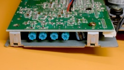
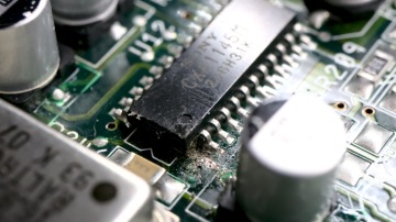
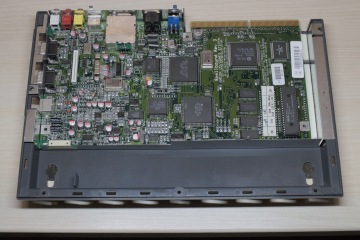
In the first part I successfully repaired an Amiga CD32 that got broken due to leaking capacitors and a botched restauration attempt. In this part I replace the laser pickup and calibrate the CD drive.
The old laser pickup of the CD32 might be worn out due to age and use. A common symptom is that the CD32 is unable to play CD-R media, or it is only capable of playing music CDs. There is no way to make the CD32 accept CD-RW media though, since they use a dye instead of pits that reflect too little light.
But before we start, read this:
CAUTION: The laser pickup is very sensitive to ESD. Use protective measures (such as an antistatic wrist band).
Make sure that the laser is always covered when the machine is turned on. Do not look into the laser beam.
I should also mention that I am not a trained technician. I have read manuals about how to calibrate CD drives, and it has worked for me. However, I don't claim that this is the best or most professional way to do a calibration.
You will need a soldering iron for the pickup replacement, and you will definitely need a scope for calibration. The drive might work without calibration after replacing the pickup, but the result will not be optimal.
Pickup Replacement
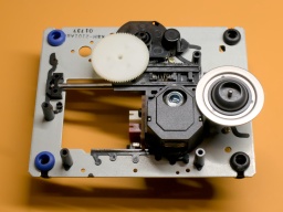
I started with disassembling the CD drive. I removed it from the case. Then I carefully disconnected the pickup and the motor unit, and removed the four screws that hold the pickup frame. There is a metal shield covering the pickup that needs to be removed as well.
The laser pickup unit is a Sony KSS210A. It is long out of production, but replicas are sold at online marketplaces for a few bucks. To remove the old pickup, I first removed the white cog wheel, then I pulled out the metal rod (it is secured by a plastic clip that can be pushed to the side). Since I was on it, I cleaned the old grease from rod and the cog wheels, and applied a bit of fresh silicone grease. After that, I mounted the new pickup and reassembled the CD drive just in the opposite order of disassembly.
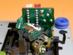
After the new pickup unit has been connected to the controller, a solder blob on the pickup unit must be removed! It protects the laser from ESD, but will damage the drive controller if it is still there when powering on the drive.
If you want to keep the old pickup module as a backup, you can also apply a solder blob there before disconnecting it.
Preparation
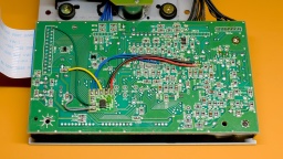
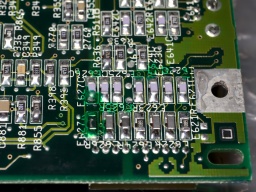
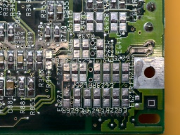
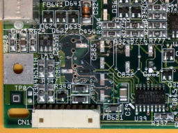
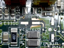
For calibration, I opened the metal shield of the drive controller, and found a surprise underneath. There was a tiny board glued to the main PCB, and connected to some points with seven wires:
I first thought this could be some kind of mod to circumvent copy protection measures, but then again, the CD32 does not have a sophisticated copy protection scheme. Later I found the answer in a YouTube video: This modification immediately cuts the power from the laser and the spindle motor when the lid of the CD drive is opened. I could find many photos of the controller board without the modification, so I guess that it was a product safety requirement for selling the CD32 on the German or European market.
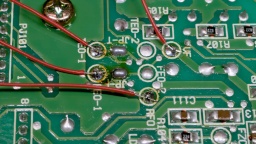
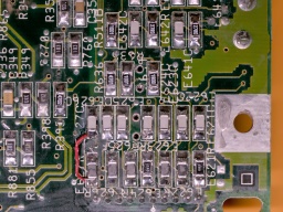
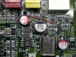
Okay, let's get back to the calibration. As a preparation, I first soldered wires to the VF, RFO, TEO-1, and FEO-1 test points. I recommend to use wires of different colors, it makes the calibration much easier. Unfortunately I only had red wire at hand, so I had to check each time which wire went where.
After that, I noted down the current settings of the four pots on the controller board, and of the pot on the laser module, using an ohmmeter. If I should mess up the calibration for some reason, I could always go back to these settings. (A photo of the pot positions is not sufficient, as very tiny changes can already make a huge difference.)
For the calibration, the drive needs to be connected to the mainboard again. The case top (with the LEDs, reset button etc) needs to be connected as well, since the CD32 won't attempt to read the CD unless the drive lid is closed. The laser pickup is moving during operation, and should have sufficient room for that.
To fix the CD to the spindle, I removed the spindle clamp from the inside of the lid, and used a bit of tape to keep the loose part fixed in the center of it. It is held to the spindle with a magnet, and ensures that the CD won't slip on the spindle.
Calibration
The calibration process is explained in this blog article by TSB. My attempts to explain it would be far worse. 😉
However, it turned out that on my drive, the process didn't work like that. After doing the first steps of the calibration, my drive was suddenly unable to spin up the CD for reading. I was lucky that I noted the pot positions (like recommended above), so I could revert to the original settings and start anew.
Then I first calibrated the TEB pot until there was approximately 0 mV between TEO-1 and VF. The drive was still working after that. However, after I calibrated FEB like documented, the drive stopped working, so I reverted that change again and moved on with calibrating the laser power.
CAUTION: Be very careful with the pot on the laser module and only turn it in very small increments. Otherwise the laser may be permanently damaged.
There is a drop of varnish on the pot from production that may require some force to break, so it might be a good idea to first turn the pot while the device is powered off, and then use an ohmmeter to return it to the factory setting that you previously noted.
To calibrate the laser power, I connected my scope to RFO and ground. Then I put a music CD on the spindle and started playing track 1. The scope should now show a so-called "eye pattern":

The tricky part is to turn the pot on the pickup module carefully while the CD is playing. I turned it very carefully until I reached a peak-to-peak voltage of about 900 mV. Take care never to exceed 1200 mV!
After that, I adjusted the FEB pot on the controller board until I reached a maximum amplitude on the eye pattern.
The last two pots, FEG and TEG, are calibrated by scoping the FEO-1 and TEO-1 test points against ground, respectively. The drive should play track 1 of an audio CD and should be in pause mode while calibrating.
I tried to find the sweet spot where the signal on the scope was as smooth as possible, and the correction noise from the optics was as silent as possible. There is a trade-off between these goals, and I found that the best results came from listening to the pickup noise and using my intuition.
The calibration is complete after that, and the CD32 can be assembled again.
One final tip: burn CD-Rs for your CD32 at the lowest speed supported by your recorder. This will increase the contrast of the data on the CD. Also, prefer CD-Rs that are not transparent when held up to the light.
