Lavender

ZX Spectrum "Chrome"

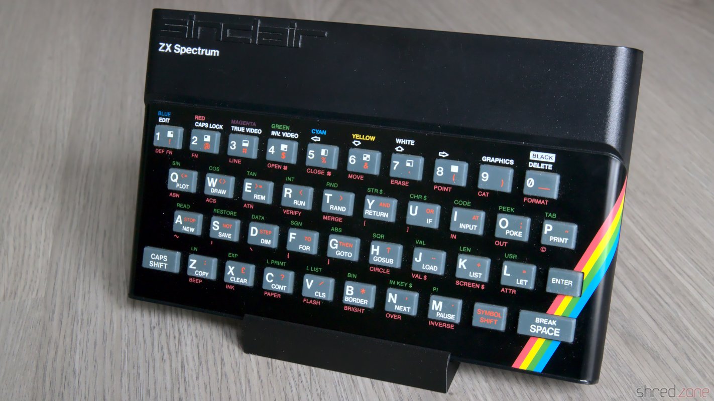
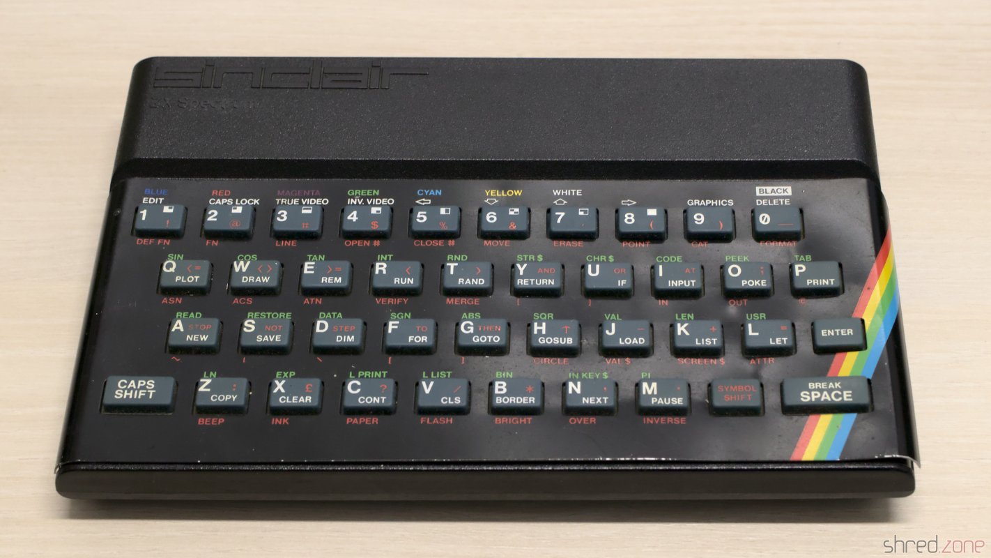
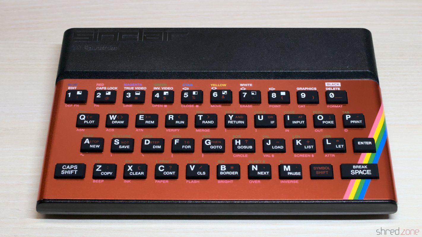
I still own two ZX Spectrum 48K from my very early days of home computing. The first is my own one, I got it from my parents as a Christmas present back in 1985. The other one was owned by a friend. It was broken and couldn't be repaired, so he first intended to throw it away, but then gave it to me instead.

So here are the two sisters…

Two Sinclair ZX Spectrum 48K

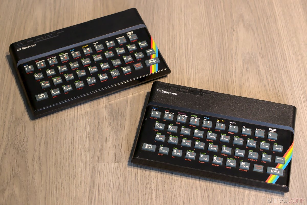
This article is about the restauration of my own ZX Spectrum. There will be a follow-up for the other one.

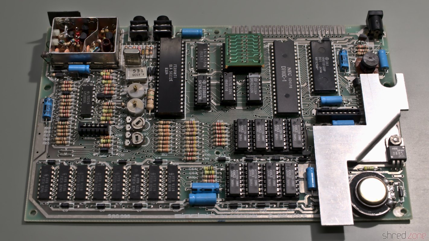
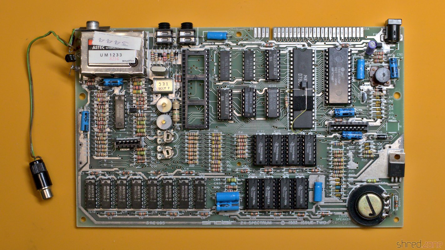
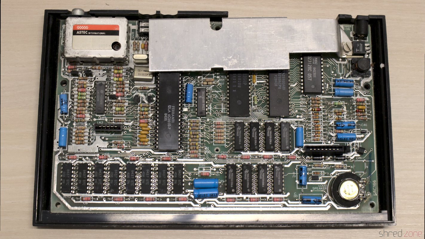
Let's have a look under the hood. This Speccy has a standard Issue Two board, with a floating transistor on the CPU as an usual factory modification of that board.

My own Speccy. The ROM, ULA, and a 74LS532 are socketed.

It looks alright so far. Let's find out if it is still working.

Composite Mod

All home computers of that era were designed to be connected to the "antenna in" of an ordinary color TV. The TV was tuned to UHF channel 36 to receive the signal. The picture quality was quite okay back in those days, but poor for today's standards.

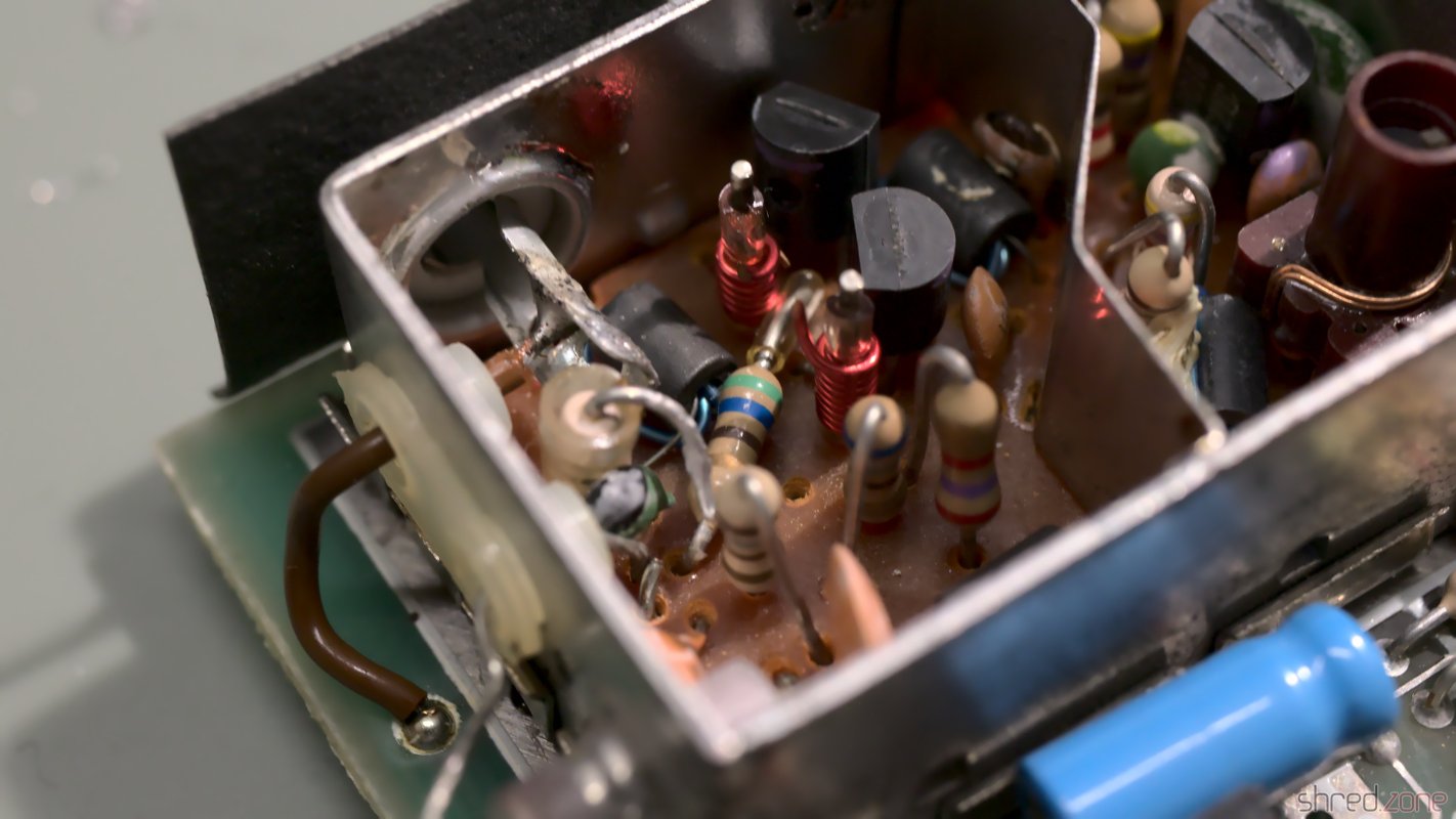
Today, almost all TVs have a composite input, so there is no need for modulating the signal any more. Luckily the ZX Spectrum can be easily modified to give a composite signal. First, the two existing wires on the side of the TV modulator are unsoldered and just bent to the side (so the mod can be reversed if desired). Inside the modulator, the resistor is disconnected from the RCA jack. Then a new wire is connected from the outside's former signal pad straight to the RCA jack.

The old two wires are removed. A new wire is connected to the left "signal" pad.Inside the modulator, the resistor is disconnected, and the wire is soldered to the RCA jack.

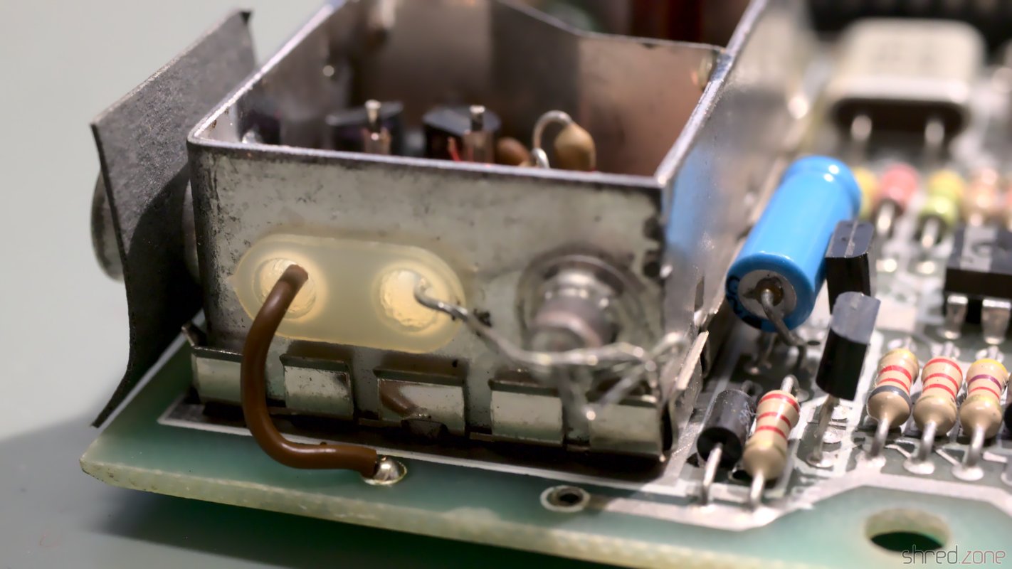
After that modification, the Spectrum can be directly connected to the TV's "composite in". The modification can be easily reverted, and there is no need to drill an additional hole into the case.

Testing

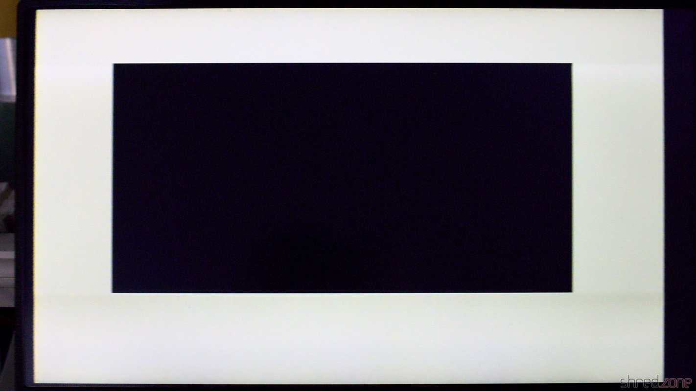
I have lost the original ZX Spectrum PSUs, but any stabilized 9 V PSU with at least 1.5 A will do as a replacement. It is very important to check the polarity of the barrel plug! Most modern PSUs have the positive pole at the inside of the plug, while the ZX Spectrum expects the positive pole at the outside:

Many Speccys certainly have been killed by using a replacement PSU with the wrong polarity.

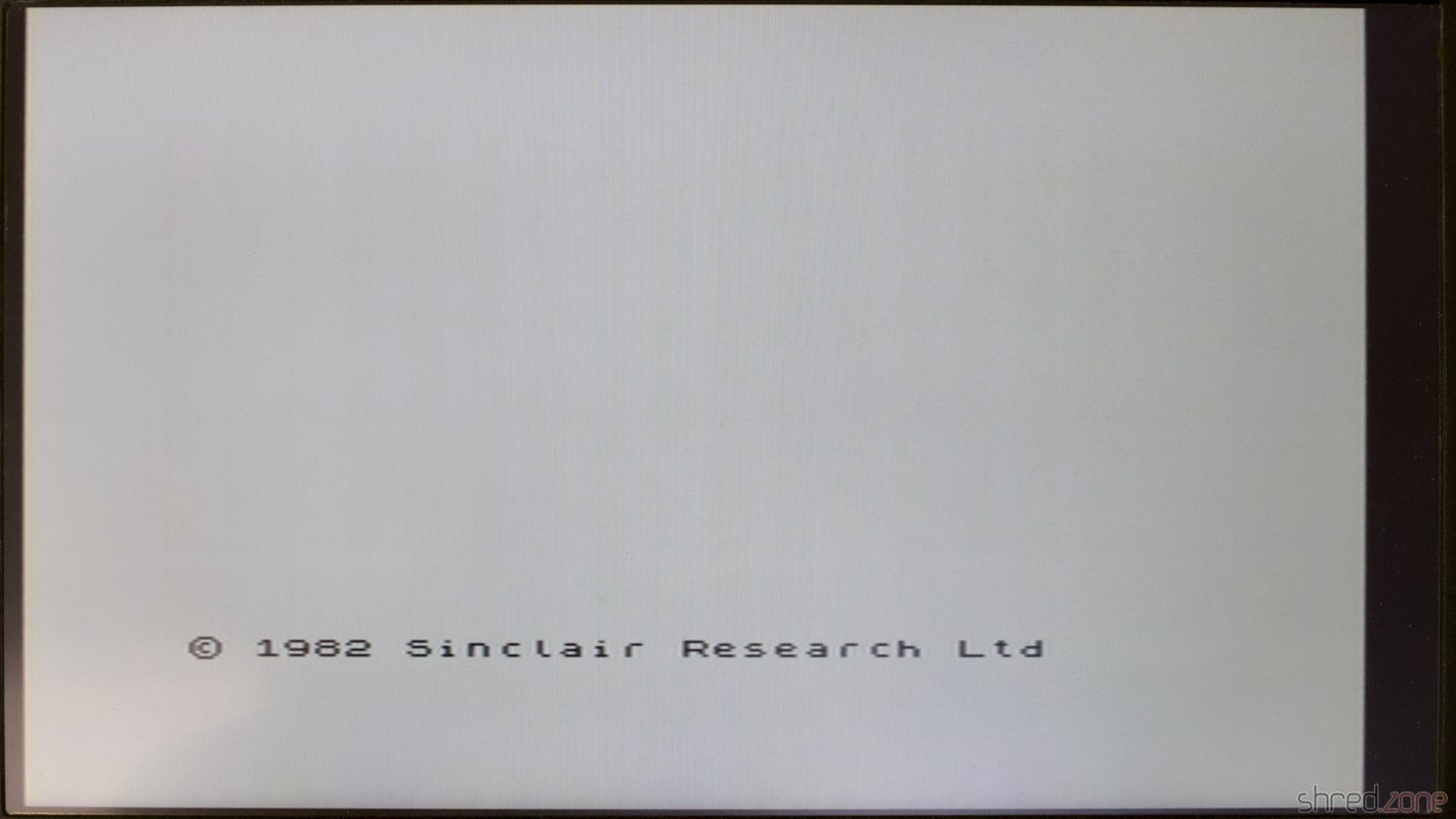
I powered it up, and to my surprise it was still working!

Almost 40 years old, and still working.

All I would need to do now is giving it the usual technical overhaul.

Recapping

The first thing is to replace the electrolytic capacitors. The old ones dry out over the years, and lose their capacity. Some may even leak and damage the PCB.

To keep the old look, many people prefer axial caps with the classic shape and a blue (or at least black) color.

High quality axial caps are difficult to find and quite expensive. I chose to use Vishay capacitors with an expected lifetime of 2,000 h. However the reference photos of the retailer deceived me. The nice black "classic" caps turned out to have an odd shape, and an aluminum or plastic grey color. They are not of an inferior quality, quite the contrary, but they just don't look vintage. I still decided to use them.

Shiny new caps that should last for much longer.Sadly these ones don't have a classic look, but they will do their job.

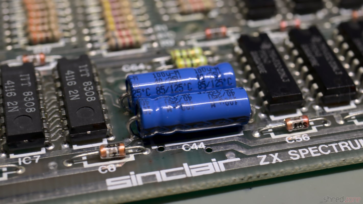
There is a trap on the Issue 2 boards: the polarity of C46 is indicated backwards on the silkscreen. The capacitor must be installed with the positive end to the left.

C46 (the upper one) is correctly installed with the positive end to the left, while the silkscreen claims it's on the right.

After the recapping, I thoroughly washed the board with IPA and a toothbrush. Then it was time for another test.

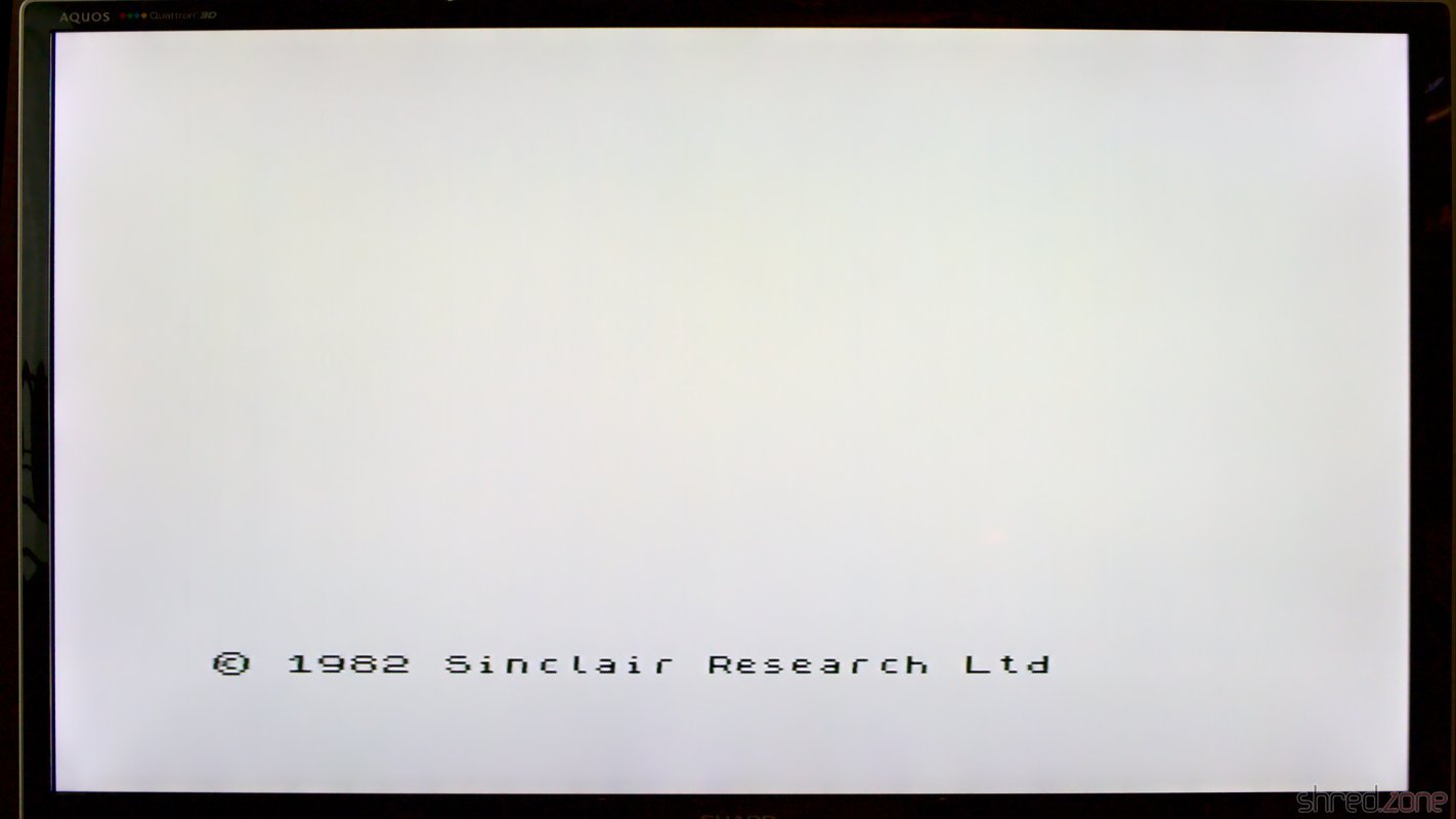
Operation Successful…

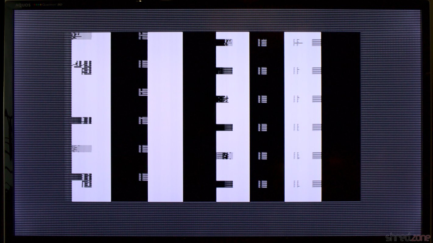
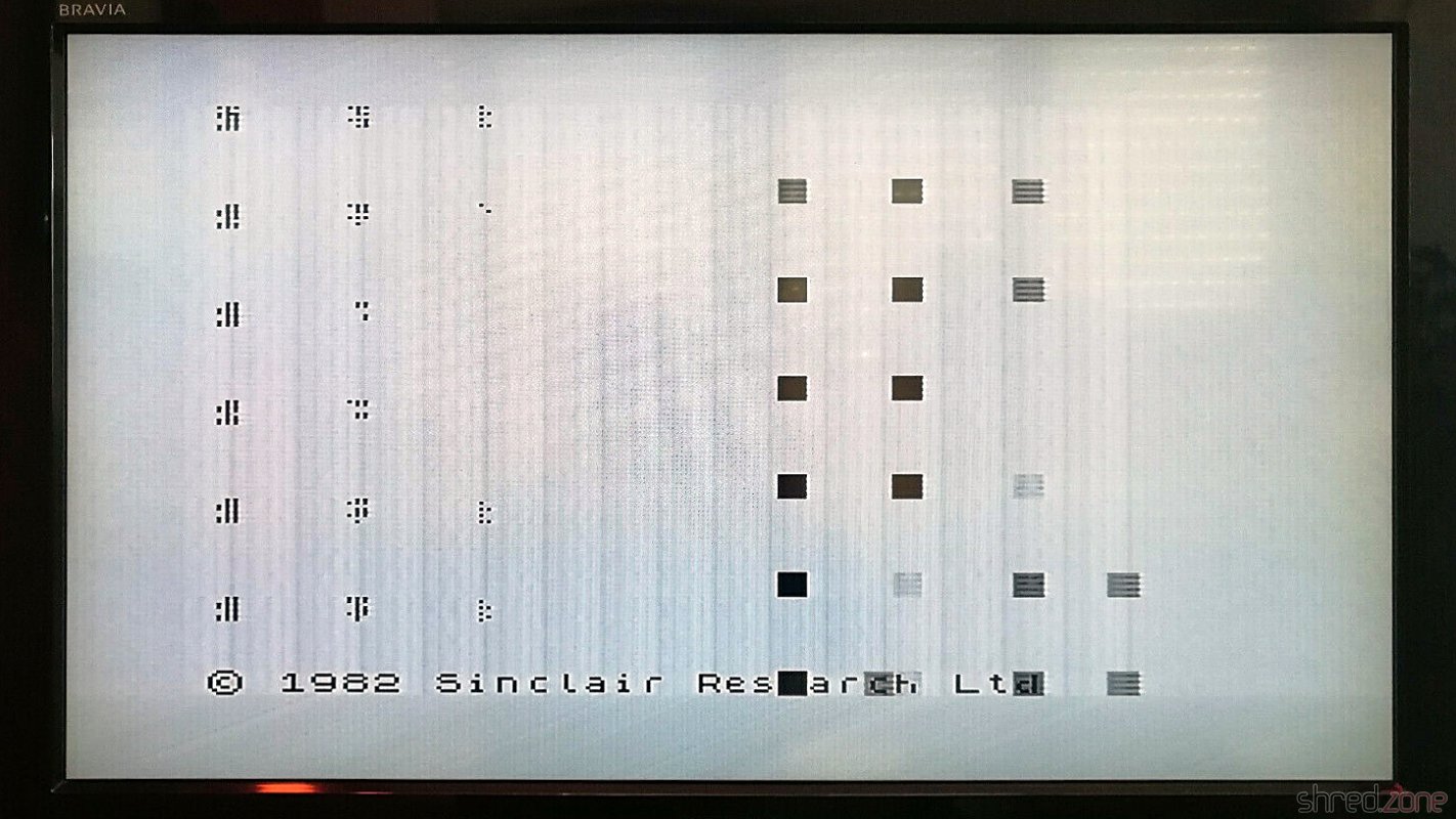
…but the patient died. This is what I saw when I powered it up again:

This doesn't look good...

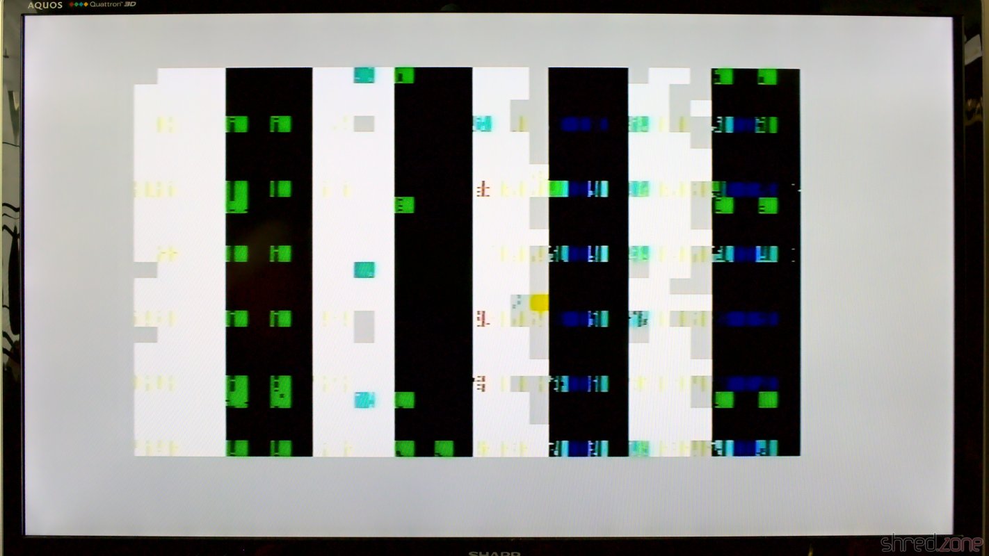
Obviously I broke something. 😯 But what?

I first checked the voltages, but they were all right. No chip was getting hot, except of the ULA, but that's normal.

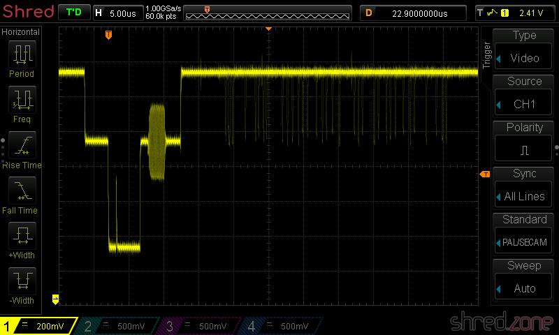
The ROM chip is socketed, so I removed it. Without the ROM, the CPU always executes the same instruction (RST 38h), which fills the memory and results in a distinct screen pattern.

Screen pattern without ROM, indicating that the CPU is working.

The pattern was there, so the CPU was fine, but it had some noise in it. I suspected a broken RAM chip, and the signal on the data bus actually looked a bit strange on the scope. I started to replace a few suspicious RAM chips, but to make a long story short, it didn't change anything. I was clearly on the wrong track.

I tested the ROM, but it was fine. I swapped the ULA with the one from the other Speccy, but it didn't help either. I checked all the capacitors I had replaced, but they had the correct values and orientation, even that infamous C46.

What has just happened that damaged a previously working Spectrum so badly?

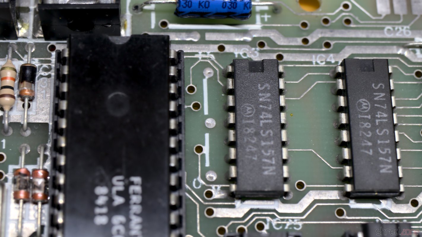
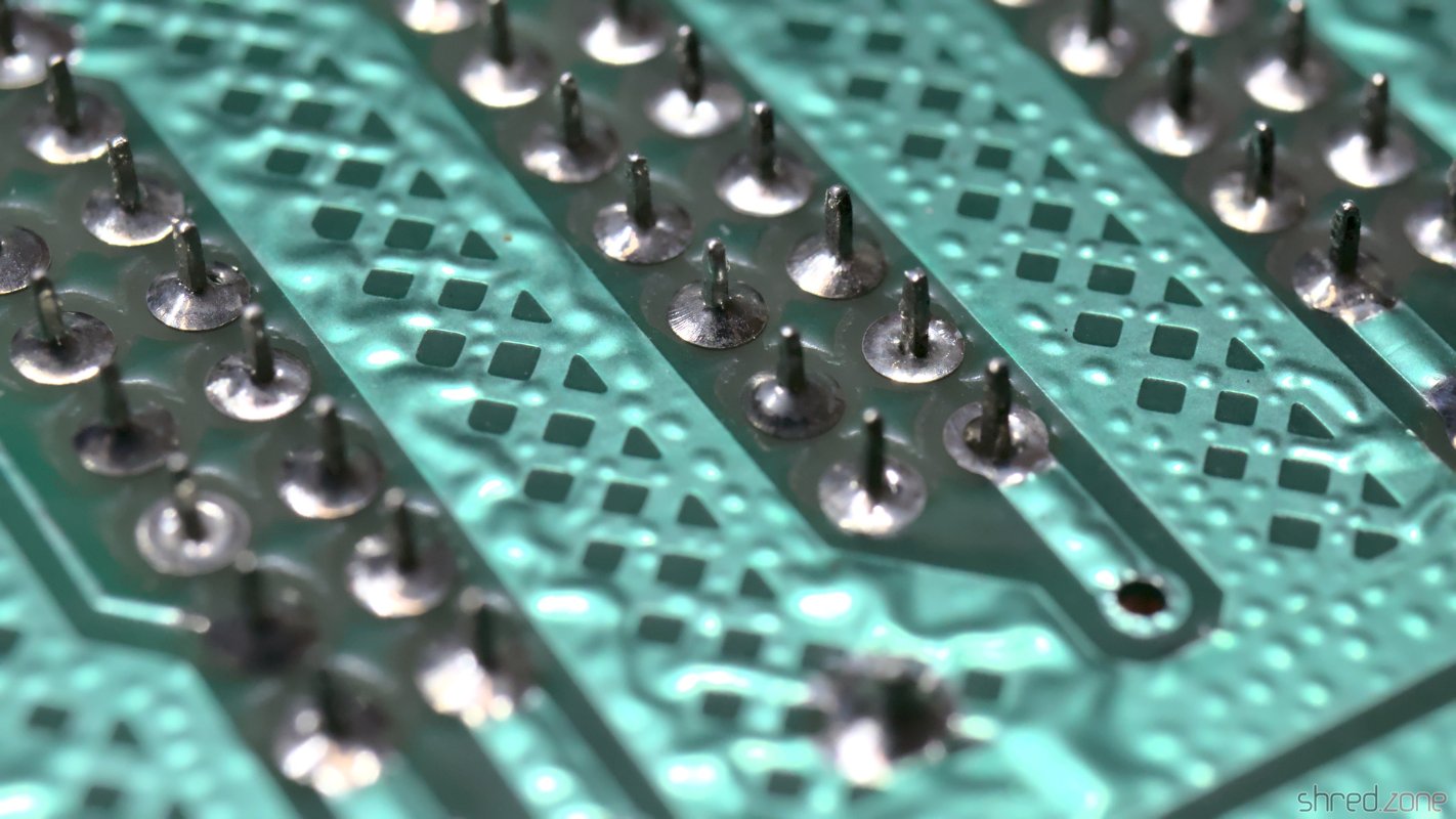
I noticed that, as the only standard chip, IC23 was socketed on that machine. It must have been from a previous repair, because unlike all the other soldering joints, the lead was yellowish there. When I touched the joints with the tip of my soldering iron, they were also sizzling. This was just scrap. I completely removed the old lead, and soldered in a new socket.

Could this have been the problem? I gave power to the Speccy. And yes, it was working again! 😄

I guess that when I cleaned the board with IPA, I partially dissolved the flux in these old soldering joints, making them cold. IC23 is used for the proper access timing of the upper RAM. With a bad timing, the upper RAM might just have disturbed the entire data bus.
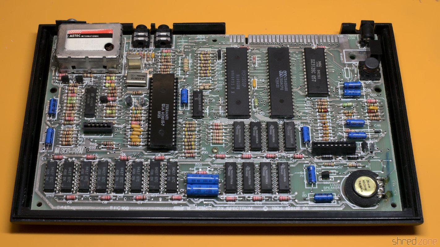
Finishing Works

With the Speccy brought back to live, I did some final cleanups.

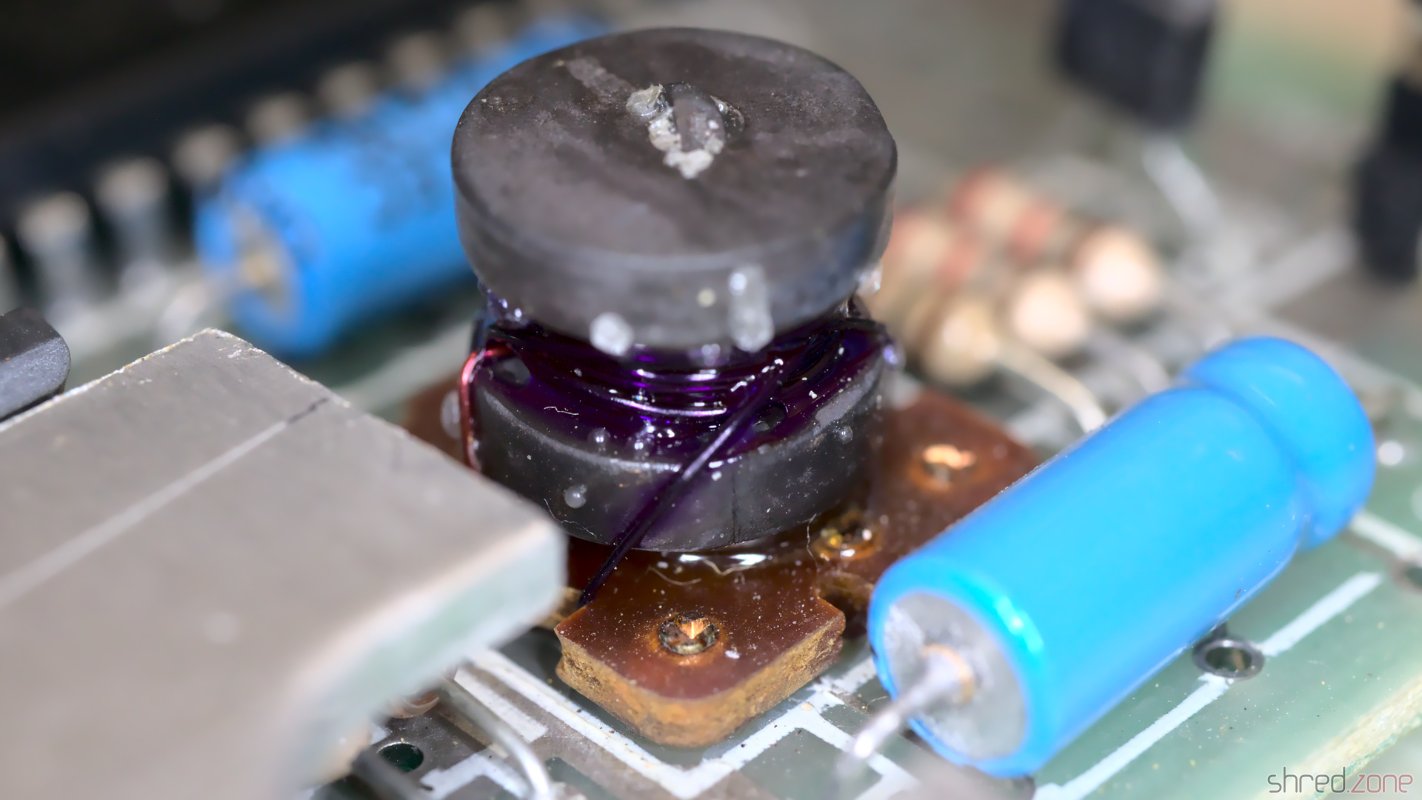
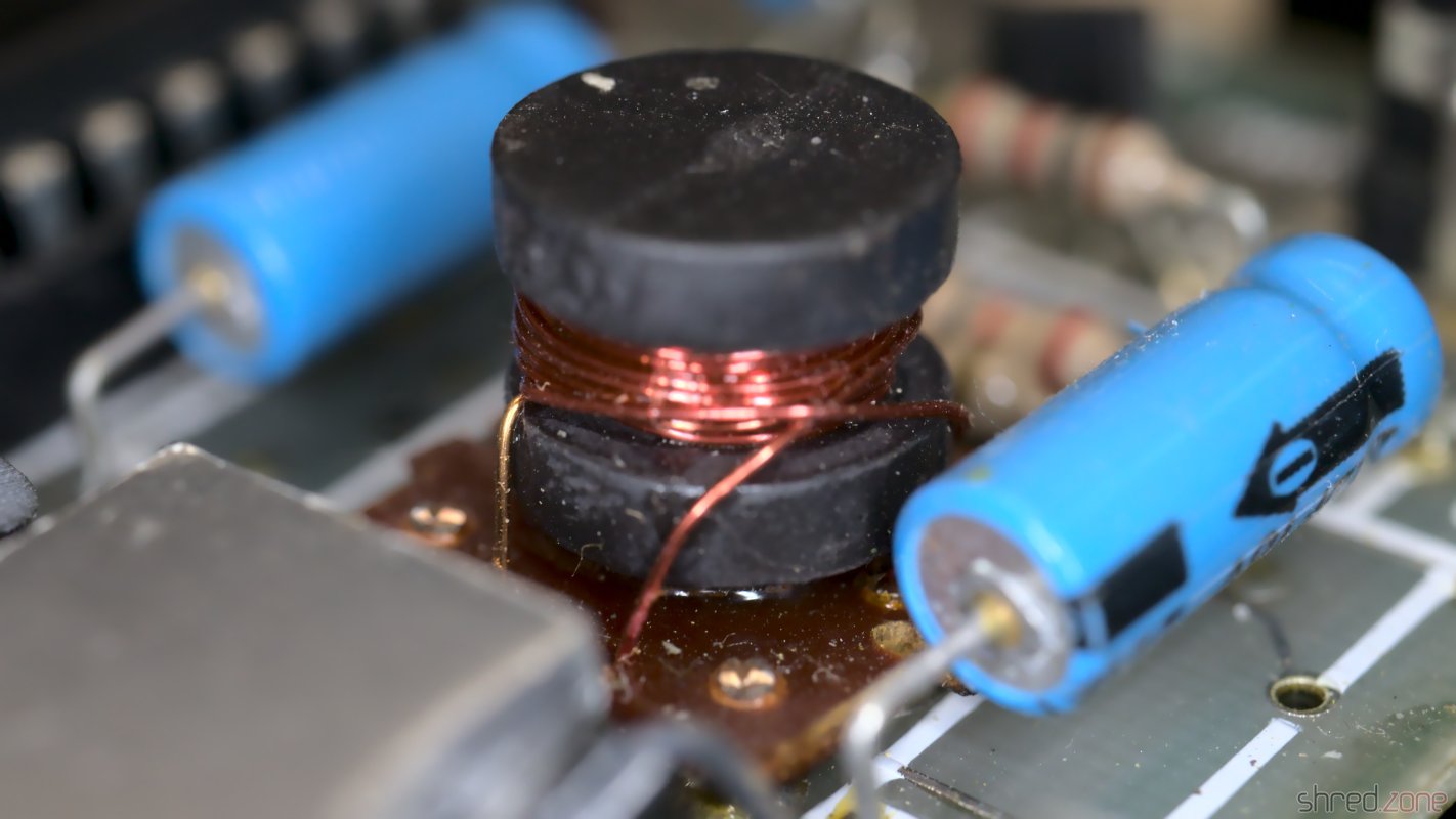
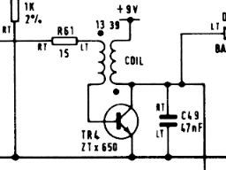
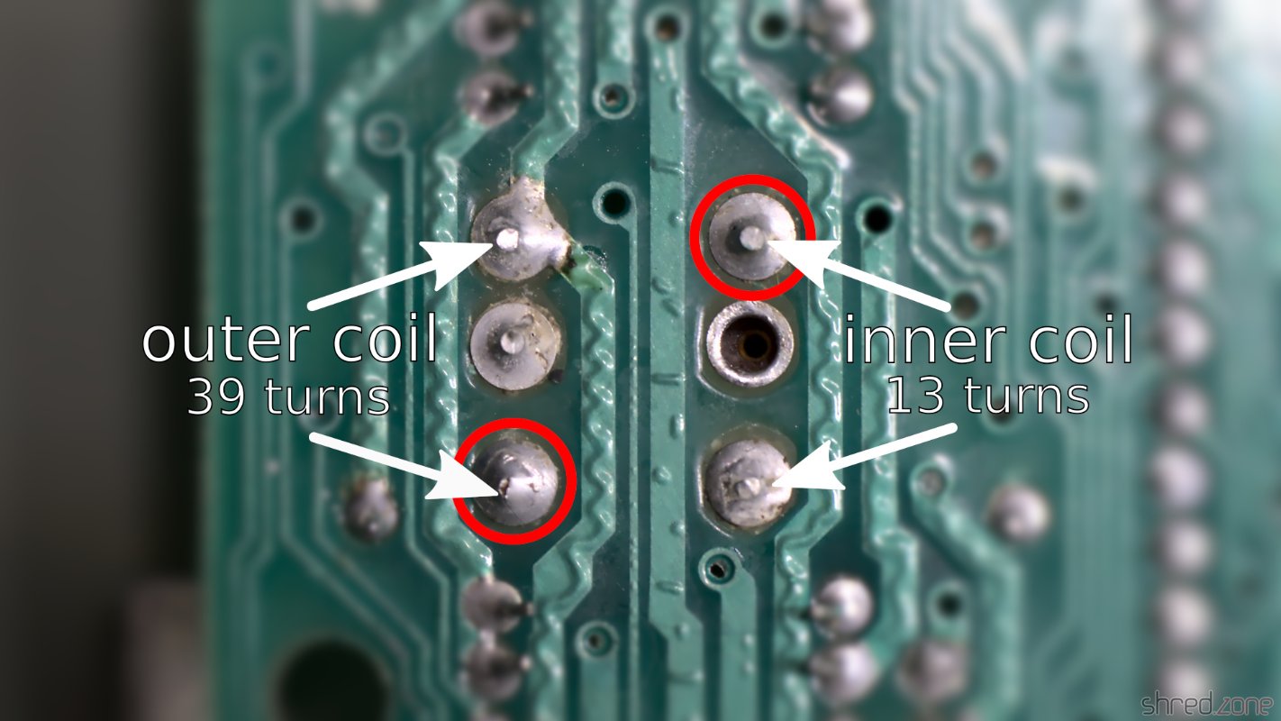
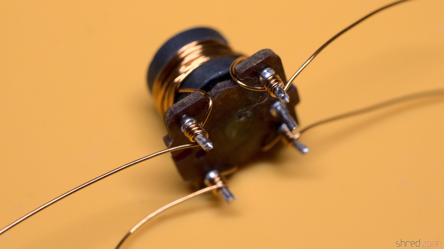
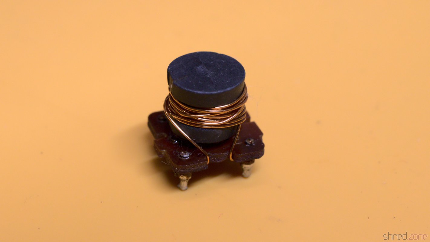
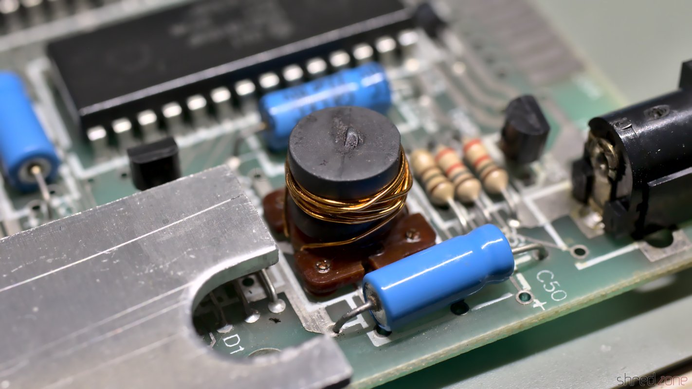
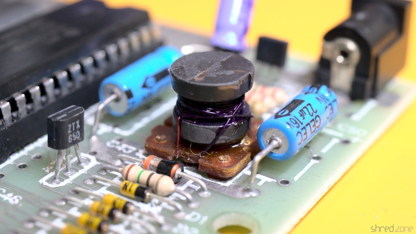
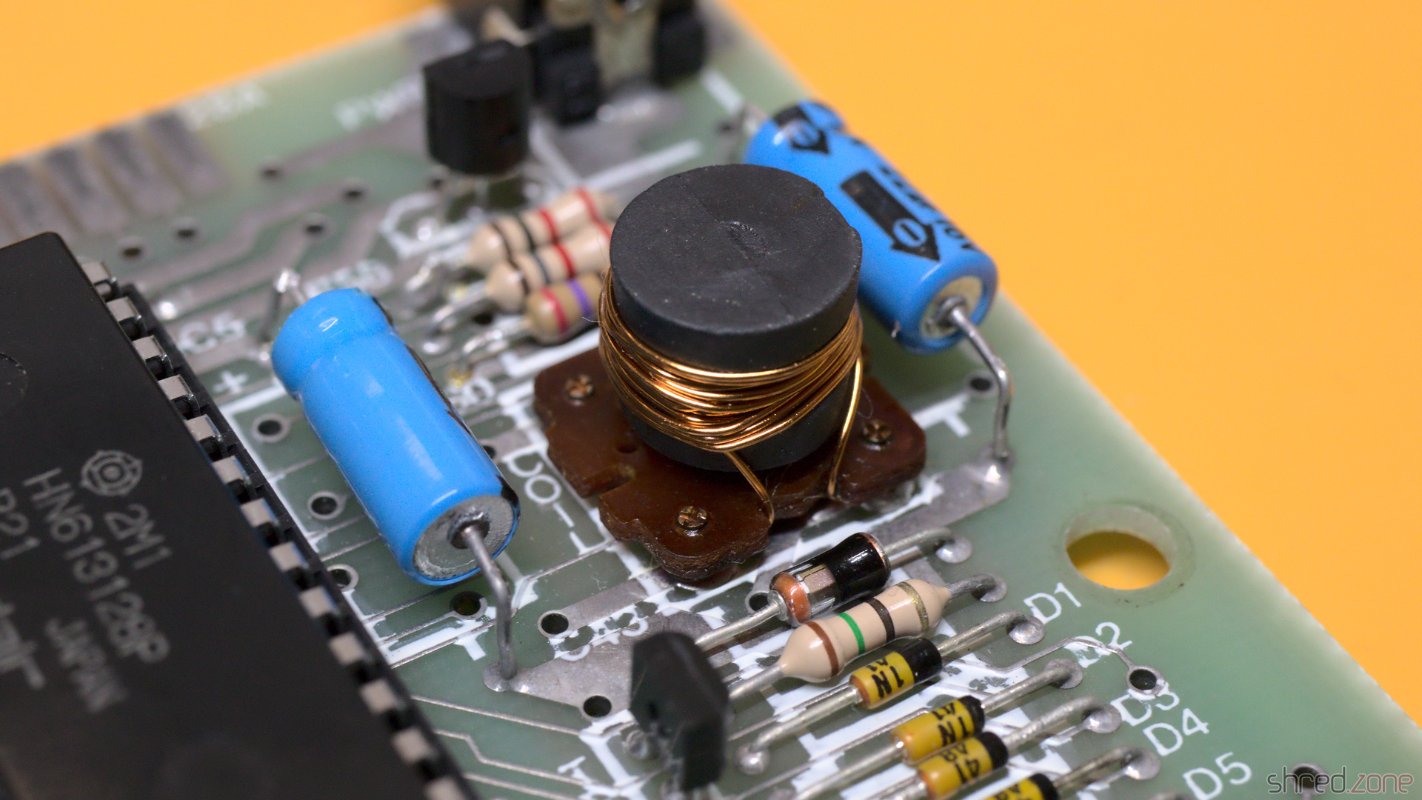
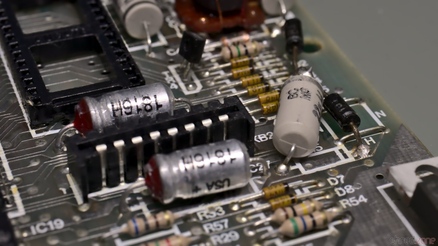
A defective TR4 is a common cause for a broken power converter. It was still working here, but I precautionary replaced it with a ZTX651, which is the more reliable successor type.

I also preemptively replaced the 7805 voltage regulator by a fresh one, and used thermal paste for better cooling. It's common in the retro scene to replace the 7805 with a modern step-down converter that does not need any cooling, but I decided against it. I like to feel the heat of a working ZX Spectrum.

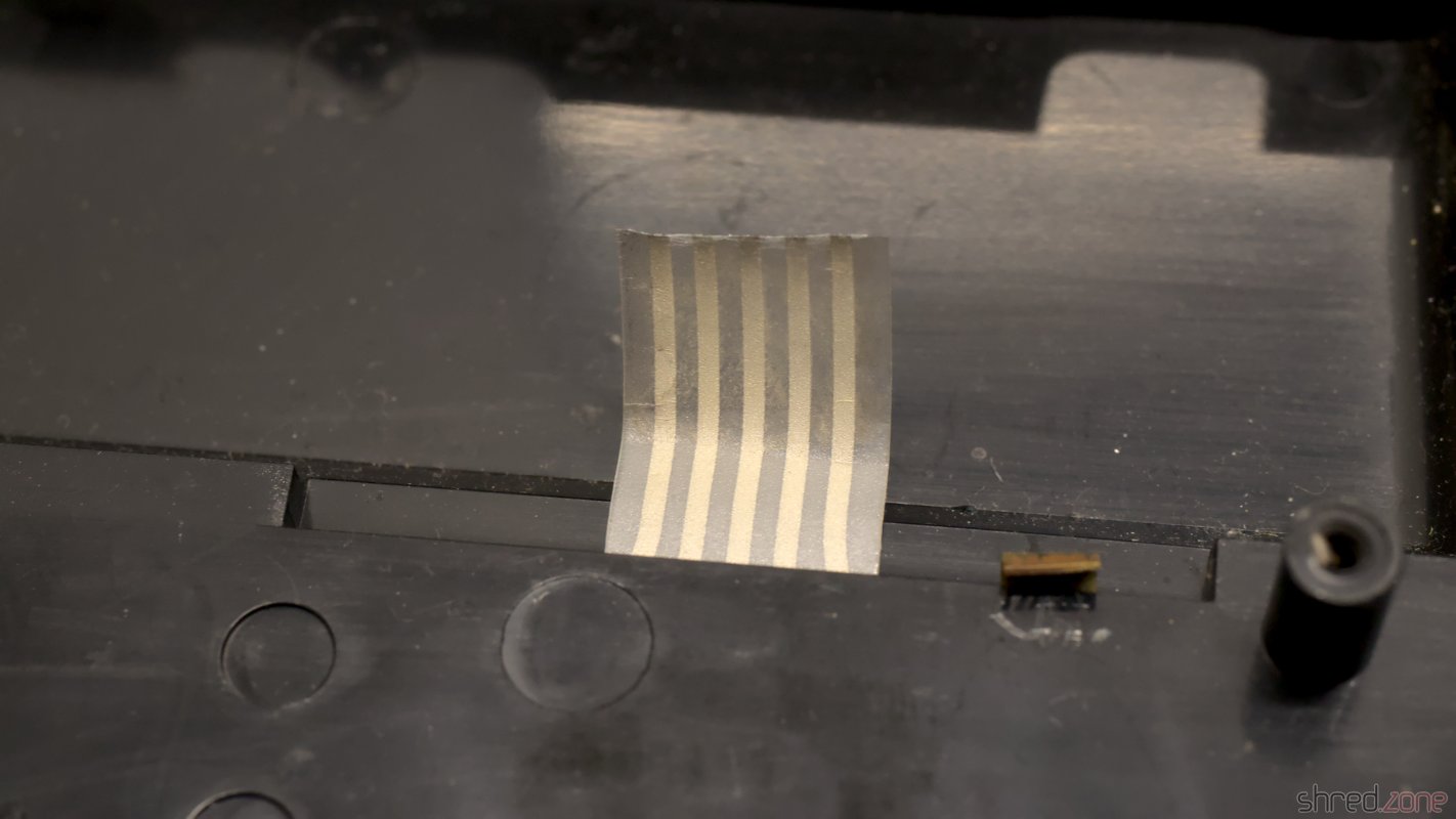
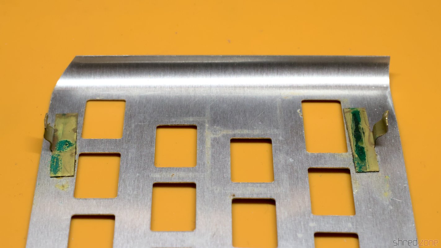
The ribbons of the keyboard membrane got brittle over the years, and already started to break. Luckily there are new membranes available on the market. And since I was on it, I also ordered a transparent replica case, a black rubber keyboard mat, and a chrome faceplate. I especially like the idea of a transparent case making the inside of this old computer visible.

The restaured ZX Spectrum 48K "Chrome Edition"

The first of both sisters is restored now. The other one might be more difficult to restore though, as it was said to be "broken beyond repair". Let's find out.

Addendum

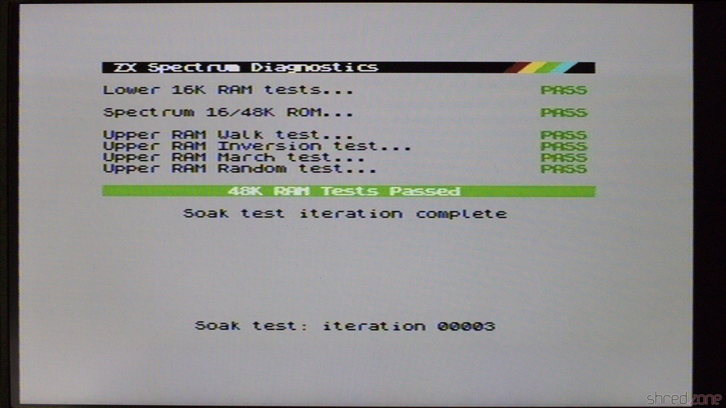
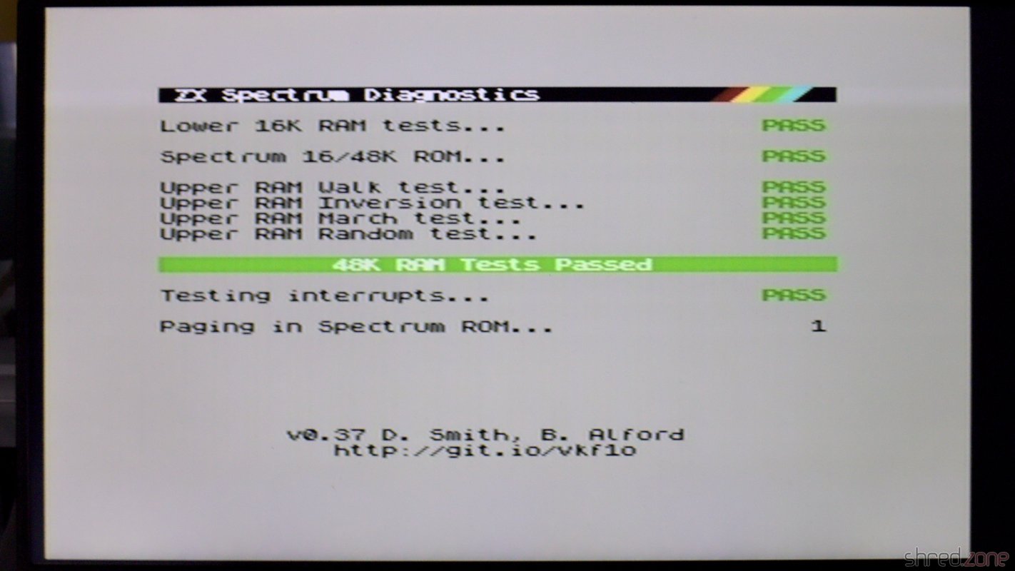
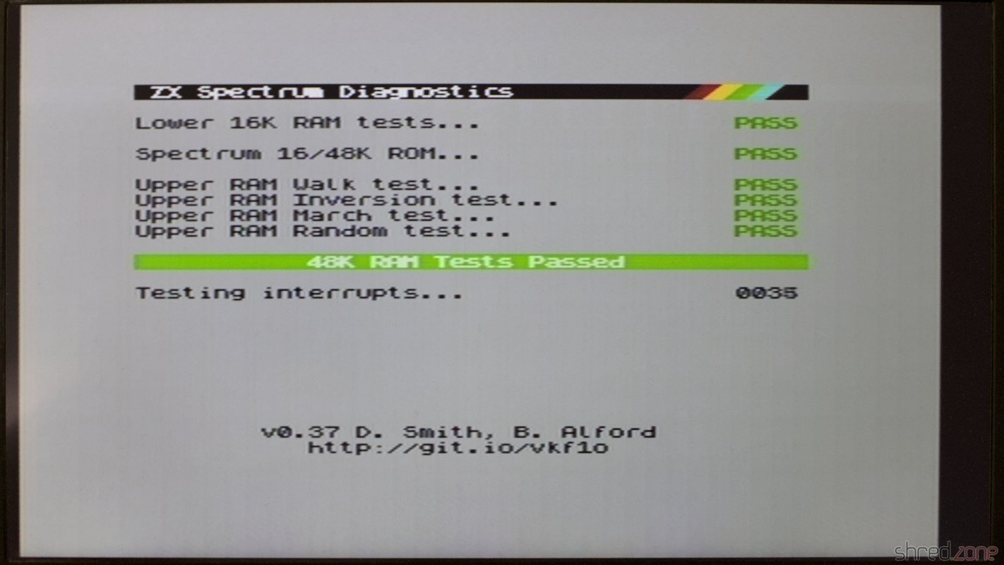
Never claim a repair is done before you ran some diagnostics. Some months later, I tested this Speccy with a Diag ROM and found that three upper RAM chips are defective.

Three upper RAM chips have failed the tests.

Fortunately the Diag ROM gives exact advice about what RAM chips need replacement. It was also fortunate that I had a sufficient number of spare chips on stock.

The faulty RAMs were replaced by new MHB4164 ones. And no, it's not that Tesla company.

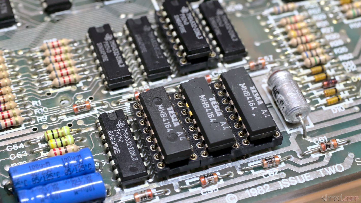
The advantage of the MHB6164 chips I used is that they are true 64KBit RAMs, so I don't need to take care that they match the other TMS4532 RAM types. After replacement, all diagnostic checks were finally green.

The upper RAM is working, and all tests are green now.

ZX Spectrum "Recoiled"

From my first days of home computing, I still have two ZX Spectrum 48K. The first one is my own one, which I restored in the previous part. This second Speccy was a donation from a friend. It was broken and written off as irreparable, so he wanted to throw it away, but I asked him to give it to me instead.

Let's find out what we have here…

Memorable Surprise

This Speccy also has an Issue Two board, but it seems to be a bit older because it has an older ULA 5C112E-3, while my own one has an ULA 6C001E-6.

Another Issue 2 board.

What surprised me was the tiny daughterboard that is used for IC26.

This one is having a tiny daughterboard though.

I first thought it was some kind of post-production fix for a PCB error, but it turned out to have a much simpler explanation. For the upper 32K RAM, Sinclair used eight 32KBit DRAM chips of various manufacturers. Those chips were actually 64KBit chips, but one half of the memory turned out to be defective after production, so they were sold with half of the capacity for cheaper.

To run a Spectrum, all eight of the chips need to have the defect in the same half. A wire bridge on the board then configured whether the "upper" or "lower" half of the RAM was to be used. For the OKI M3732 chips that were used on this board, the internal memory cell addressing is a bit different though. Let's put it that way, on these chips either the "left" or "right" half was defective. The tiny daughterboard just takes care of the necessary modification on the address lines to run the OKI chips. Maybe they have just been the cheapest around when Sinclair produced this batch. Starting with the issue 3 boards there were jumpers for the OKI chips, and the daughterboard was not needed any more.

Damage Assessment

In order to see anything, I first did the "composite mod" that I also did on my other ZX Spectrum. It just needs a wire and a few minutes of work, so it is well invested time even if this ZX Spectrum actually turns out to be irreparable.

After that, I connected the Speccy to the TV, took a deep breath, and then turned on the power.

This isn't looking good.

Yes, this computer is definitely broken.

New Coil

The first thing that should be tested on a broken ZX Spectrum is if the voltages are correct. The 4116 RAM chips need three of them: +5V, +12V, and -5V. The +5V were there, but instead of +12V I only got +7V, while the -5V were completely missing.

With further checks I found the culprit: the coil was shortened. And there must have been a lot of heat involved, as the insulation plastics was completely melted and got a dark purple color. The left photo shows this coil, the right one shows a good coil for comparison.

The insulator is melted. The primary and secondary side are shorted.This is how a good coil is supposed to look.

That kind of damage usually happens when an expansion cartridge is removed while the ZX Spectrum is still powered, causing a short circuit on the power lines. This poor computer must have given one last smoke signal before its decease.

The coil was custom made for the Spectrum. One can still get remakes today, but they are quite expensive. So why not just wind a new one myself?

First I thoroughly removed all the old copper wire and the charred insulator plastics. I was hoping that I could just unwind the old coils and count the number of windings, but the insulation was melted to a single lump of plastic. The wire eventually tore, and I had to use a cutter to get the remains off the ferrite core. When I was done, it looked like the coil just exploded on my desk.

The battlefield.

Luckily, the circuit diagram gives us all the information we need to know.

The original coil wire had a diameter of 28AWG (or 0.32mm), so we need insulated transformer copper wire of the same strength. For the inner coil we need about 30cm of wire, for the outer coil about 100cm.

First we start with the inner coil. Wind a bit of the wire firmly around the pin marked in red on the next photo, then do 13 turns around the ferrite core, then wind the wire firmly to the other pin. The windings on the ferrite won't need to be perfect, but should still be as tight as possible. I recommend to rewind the inner coil even if it appears to be intact, as the insulation might already be damaged.

After that, we do the same with the outer coil, having 39 turns. It is important that both coils are wound in the same direction. It doesn't matter whether both coils are wound clockwise or counter-clockwise, as long as you use the same direction for both coils. The original coils are wound counter-clockwise when looked from above.

First the inner coil with 13 turns, then the outer coil with 39 turns. Start with the pin marked red. Use the same direction for both coils.

Finally, use a lighter to remove the insulation on all four pins, then use flux and a bit of solder to fix the wire ends to the pins. Now check with a multimeter. Both the primary and secondary coil should have less than 1Ω, but there should be no resistance between both coils.

The wires are wound around the core, and then wrapped around the pins. The refurbished coil, ready to be soldered back.

Now the coil can be soldered to the board again. The fifth pin serves as a key for the correct orientation.

I could only get 0.35mm wire, so my coil got a bit too "fat".

A shortened coil always causes secondary damage, so I preemptively replaced the components that usually fail as well:

  • TR4: It can (and should) be replaced with a ZTX651, which is stronger and more reliable. They can still be found at good electronic retailers. I was researching for a standard transistor as replacement, but even though there were some types, the ZTX651 was always the strongest recommendation.
  • TR5: The original type is not available any more, but can be replaced with a ZTX751 or a standard BC557 (which must be mounted facing in the opposite direction).
  • D16: This can be any standard 5V1 Zener diode.

After that, I connected it to power, and (to my surprise, to be honest) all the three voltages were back and correct.

What's Next?

The picture on the TV was still unchanged, but I had already expected that more components would be damaged.

I checked the temperatures of the ICs with my finger. If you try this at home, be very careful because a broken chip can get so hot it can easily burn your skin within a second.

The ULA got warm, but that's normal. The CPU also got a bit warm, which wouldn't be a surprise on modern computers, but the Z80A is supposed to stay cold. I unsoldered it, and replaced it with a 40 pin socket and a used SGS Z80A CPU that I once recovered from a broken ZX-81.

I powered it up again, and it just worked! 🎉

So there was just a burnt coil and a broken CPU. This repair was much easier than I had expected.

Finishing Works

Like on my other ZX Spectrum, I first replaced all the old electrolytic capacitors. I also used a fresh 7805 voltage regulator, and thermal paste for better cooling.

My first Spectrum got a transparent case and a chrome faceplate. For this ZX Spectrum I decided to keep the original look, so I just replaced the broken keyboard membrane. The old faceplace had some visible dents and scratches, so it was replaced as well. I then washed the original case in warm water with a bit of dish detergent, and then put it all back together.

The restored ZX Spectrum 48K.

And that is the story of the two sisters who got a nice makeover, and are now fit for the next 30 years. 🙂

ZX Spectrum "Beauty"

When I started to refurbish old computers in 2021, I couldn't imagine that it was so much fun. 😁 The other day I bought another ZX Spectrum. According to the seller, it had some strange artefacts on the screen and also stability issues, so it was sold as defective. When I tried it at home, it was even worse. I just got a black screen on a white border.

Screenshot made by the seller. Here the screen was just black with a white border.

Inside the case I found an Issue 2 board. The previous owner has added a composite output on a separate connector. As the age of TVs with tuners is definitely over, there is no need to keep the modulator output. I will do my own composite mod instead, and remove this ugly cable that was hanging out.

The manufacturing dates of the components tell an interesting story. This computer has probably been manufactured around the end of 1982. However, all chips that are related to the upper 32KB RAM are socketed, and some were made in 1983. I guess it was originally built as 16K model, and has been extended to the full 48K a year later. As the only chip on this computer, the ULA was made in 1984, so maybe it had been replaced around then.

It's an Issue 2 board with a composite mod on a separate connector. I removed the ULA for testing.

My main suspicion was that the ULA was broken, so I put it into one of my working Spectrums, and was happy to find it in working order. The problem must be somewhere else.

The usual first step is to check the voltages. And bingo, the 12V line had around 7V, and the -5V line was flat. This sounded very familiar, and a look at the coil confirmed my suspicion. The coil had a purple color, and a short between the primary and secondary winding. I guess the coil was already pre-damaged when the Spectrum was sold, causing the artifacts because of poor voltages on the lower RAM chips. When I powered up the computer at home, I eventually killed it.

Well, it's not the first time I had to deal with a broken coil. I unsoldered it, rewound it, and replaced the semiconductors that usually get grilled as a result. Then I powered the system again, and found that all voltages were back to normal. Success!

A shorted coil. The purple color is looking very familiar. It was the same on another Spectrum. The repaired coil.

I put the ULA back into its socket, so I could check what else is broken. And (to my displeasure, to be honest) the computer just came up and was working again.

This is looking good! The computer is working again!

What a spoilsport! I was hoping to have some more repair fun with that machine. 😉

Okay, what next? I started with replacing the electrolytic capacitors with fresh ones. Then I found something strange: A wire link was missing that was supposed to be there.

There is supposed to be a wire link here.

That link is important. The upper 32K RAM chips are actually 64K RAM chips, where one half of the memory turned out to be faulty after production, so they were sold with half the size for cheaper. The link configures which half of the memory is to be used. There is no pull-up resistor, so keeping it open is not a valid option. It might cause the upper RAM to randomly flip between the working and faulty memory half. I doubt that this computer has ever been working stable after it was modified to 48K. This link has just been forgotten by whoever did the modification.

The RAM chips are TMS4532-20NL4. The trailing 4 indicates that the upper part of the memory is to be used, so I added a link between the center hole and the "+5V" hole. A trailing 3 would require a link between the center hole and "0V".

I soldered in the link and replaced all electrolytic caps with Vishay ones. I also replaced the 7805 voltage regulator with a Traco Power TSR 1-2450. This modern DC/DC converter is a drop-in replacement that needs no heatsink, and is small enough to still fit into a classic ZX Spectrum case.

Wire link added and electrolytic capacitors replaced.

Issue 2 Spectrum boards have two variable resistors, VR1 and VR2, for color calibration. With the aid of an oscilloscope, calibration is a matter of a minute. I connected the scope to the composite video output (or to the video input of the modulator), and then adjusted both resistors until the signal was looking as smooth as possible. There is a blog article at Spectrum for Everyone that gives more details about the calibration.

Finally, I ran the ZX Spectrum Diagnostics tool. All tests passed, even those of the upper RAM.

All diagnostic checks passed.

Another repair job well done. 😄

So there is my 3rd ZX Spectrum. Above all, I like the exceptionally good condition of the case. It seems that the computer has barely been used in its 40 years. The keys and faceplate actually look pristine, and there are also only very few and small scratchmarks.

The case is in an excellent state, considering it's 40 years old.

ZX Spectrum "Portugal"

And yet another Speccy that I could buy for a good price. The seller said it was "untested", but I allege that he knew very well it was broken. It's fine for me as I mainly buy those things for the repair fun. 😁

The computer was in a sad condition when I got it. What's remarkable is that the machine was "assembled in Portugal". It's the first time I see this, and to be honest, it was one of the reasons why I wanted to have it. According to the very few information I found on the internet, those machines were intended for the Portugese and South American market, but some of them also made it to the UK and other European countries.

The faceplate was heavily bent, and a connector of the keyboard membrane was broken off. It seems that the previous owner tried to replace the membrane, but wasn't able to remove the faceplate.

The new Speccy is in a poor condition. One of the membrane connectors was broken off and missing.  It was assembled in Portugal.

That's the first hint that the machine wasn't "untested", but underwent a botched repair attempt.

I got the second hint when I tried to power up the machine, but found that it was completely dead, with all the voltages missing. The 5V is generated by an 7805 voltage regulator. It could just have died of old age. But considering the other hint, I rather guess that the previous owner has tried to power this machine with a standard 9V power supply. It has a reversed polarity, which kills the 7805 instantly, and usually damages the lower RAM chips and other components.

Let's have a look inside. There's an Issue 6A board inside, which is the final revision of the board. But besides that, there were no surprises. Anyway it's the first Issue 6A board I own, so I'm happy to have it.

An Issue 6A board, probably built around end of 1984.

The 7805 regulator is definitely broken, but I would have replaced it with a Traco Power DC/DC converter anyway. After I replaced it, the 5V line was back. To my surprise, the 12V and -5V lines were also back, so at least there was no further damage to the power supply.

I did my usual composite mod. Then I connected the computer to my monitor and powered it up to find out what else is broken. To my surprise the start screen appeared, and the Diag ROM also found that all RAM chips are working.

The Speccy just booted up. The Diag ROM found no further defects.

Okay, so much for the "repair fun" I was hoping to get. On the other hand, this board has a second custom chip, the ZX8401, also known as ZXMUX chip. If it would have been damaged, repair would have been a lot more difficult. Not impossible though, since the ZXMUX can be simulated by a few standard SMD chips.

Now that the Speccy was repaired, I continued with replacing the electrolytic capacitors. I also found and fixed a lot of cold joints at the lower RAM chips. The refurbishment of the board was completed after that.

The board after repairing and recapping. A lot of cold solder joints.

Let's have a look at the case. The membrane connector was broken, but luckily there are new membranes available at retro shops. The previous owner tried to remove the faceplate, which is most often glued to the case. Most often, but not here. On this computer, the faceplate was just held in place by four brackets. All that would have needed to be done was to open these brackets and then easily pull of the faceplate.

The faceplate is held by four brackets that can be easily seen on the inside. All that needs to be done is to open them. The faceplate itself is not glued to the case.

Sadly, thanks to the botched repair attempt, the original faceplate was bent too much to be recoverable. It also had some visible scratches. I wished I could have salvaged it, but I decided to replace it with a new one instead. This time I took a metallic red faceplate, which looks as hot as a sunset in Portugal. 😉

My new ZX Spectrum "Assembled in Portugal".

And there it is, another ZX Spectrum for my collection.