I recently got two Competition Pro Mini joysticks. The full-size Competition Pro was probably one of the most famous joysticks back in the 1980s and early 1990s. This model was said to be unbreakable, and was able to withstand even long and intensive gaming sessions. If one of the microswitches eventually failed, it was easy to get a new one from an electronics store and replace it just by using a screwdriver, no soldering required.
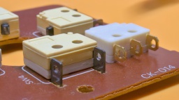
The Mini models came to the market in 1992, and were by far not that robust. My two examples had broken microswitches at the left direction. The microswitches are soldered to the PCB, and they are also out of production.
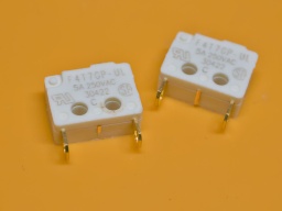
The closest available replacement is the Saia-Burgess F4T7UL and F4T7GPUL (the latter one with gold-plated contacts). Unfortunately it has different solder tails, so it cannot be used as a drop-in replacment.
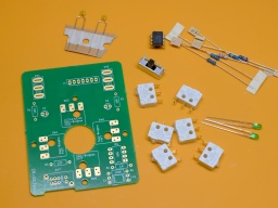
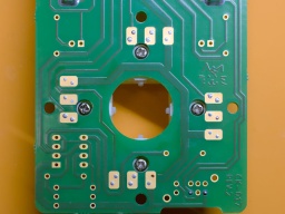
I decided to build up a completely new PCB by InsaneDruid instead. It is a replica board with exactly the same size and fuctionality, but it is prepared to use the Saia-Burgess switches.
Auto-fire Model
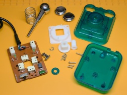
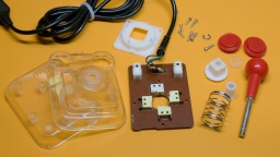
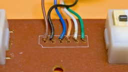
The first thing I did was to completely disassemble the joystick. All plastic parts were cleaned in an ultrasonic bath. Meanwhile I noted the color order of the wires before cutting the cable from the old board.
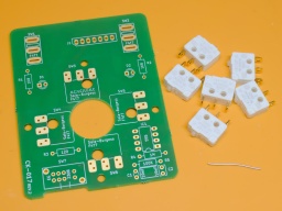
The new board only needs very few components. Except of the switches, all of them are standard ones that can be found in any electronic store. The switches can be found at distributors like Mouser.
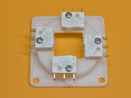
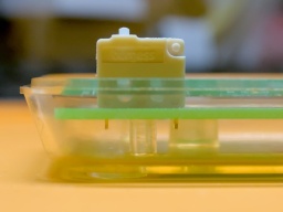
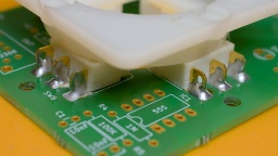
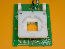
For the four directions, I first mounted the microswitches to the holder frame. This way it will be easier to perfectly align the switches to the PCB.
For the fire buttons, the middle solder tail needs to be cut off. Otherwise it will collide with a peg of the bottom case shell later.
Usually we would start with the flattest component, but in this case, I recommend to start with the four direction switches. Position them to the frame so the four screws are perfectly aligned with the corresponding PCB holes. Make sure that the two LED holes are aligned to the "up" direction. Then start soldering the switches to the PCB, using a generous amount of solder.
Additionally you can use wire brackets to secure the switches using the provided mounting holes. I was too lazy to do that though.
The remaining components are just soldered to the board. Finally the original cable is wired to the board, with the original order of wire colors.
After that, the joystick is ready for reassembly.
Standard Model
My other joystick is a standard model without auto-fire function. Again, I disassembled it. All plastic parts were cleaned, while I noted down the color order of the wires.
The cable of this model does not provide a +5V supply. For this reason, there is no need to populate the components for the auto-fire. We can also save the LEDs, as they won't light up.
The preparation is the same as for the other joystick. The four direction switches are mounted to the frame, and the two fire switches lose their middle solder tail. After that, the frame with the switches is aligned and soldered to the board, followed by the fire switches.
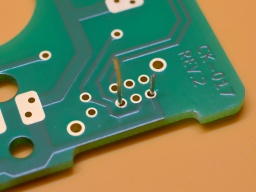
We do not need to populate the mode switch. However, we need to solder in a wire bridge to pins 5 and 7 (see photo), otherwise the fire buttons won't work at all.
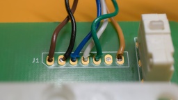
The wires need a different order. On the original board, the "fire" signal is at the third position from the right (the orange wire on my joystick). On the new board, that signal is on the very right pad. The one left from it stays empty. For the remaining wires, the original order can be kept.
After that, this board is completed as well, and the joystick can be reassembled.
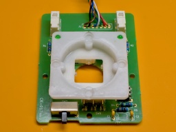
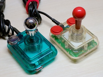
The joysticks look as good as new now, with their clean case and their brand new boards.
The ENIG plated PCBs are a true eye-catcher in their transparent cases.
