In the first part, I repaired the motherboard of an Amiga CD³² that was damaged by leaking capacitors and a botched restoration attempt. In this part, I am now replacing the laser unit and calibrating the CD drive.
The old laser unit in most CD³²s is likely worn out due to age and use. A common symptom is that the CD³² no longer plays CD-R media or only recognises music CDs. Incidentally, the CD³² generally does not recognise CD-RW media, as these use a dye instead of pits, which reflects too little light. This cannot be fixed even with a new laser unit.
Before we start, a heads-up:
WARNING: The laser unit is very sensitive to electrostatic discharge. Always take protective measures, e.g. by wearing an antistatic wrist strap.
Ensure that the laser is always covered when the computer is switched on (e.g. with a CD or a piece of paper). Do not look into the laser beam.
I would also like to mention at this point that I am not a trained technician. I have read guides on calibrating CD drives, and it worked for me. However, I do not claim that this is the best or most professional way to perform a calibration.
To replace the pick-up, a soldering iron and definitely an oscilloscope for the subsequent calibration are required. It might be possible without calibration, but the result will not be optimal.
Replacing the laser unit
First, I removed the CD drive from the case. Then I carefully separated the mechanical unit from the controller, and removed the four screws holding the frame of the mechanical unit. The metal shielding covering the pick-up must also be removed.
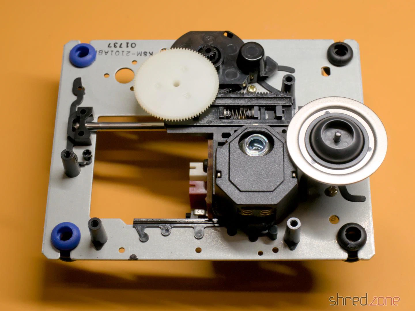
The pick-up is a Sony KSS210A. It is out of production for a long time, but replicas are offered on online marketplaces for a few euros. To remove the old unit, I first took off the white cog and then pulled out the metal rod (it is only held by a plastic clip that can be pushed to the side). While I was at it, I removed the old grease from the rod and the cogs, and then applied a little silicone grease. After that, I mounted the new unit and reassembled the CD drive in reverse order.
Important: Immediately after the new laser unit is connected to the controller, a solder blob on the laser unit must be removed! It protects the laser from static electricity, but would irreparably damage the drive controller if it is still present when switched on.
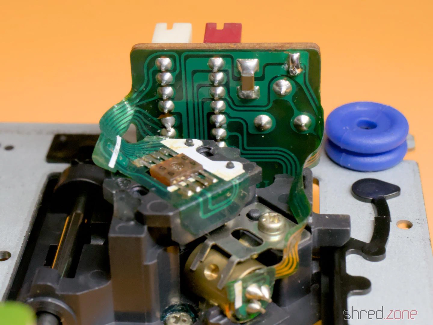
If you want to keep the original laser module, you should also apply a solder blob there before disconnecting it.
Preparation
I removed the metal shielding of the drive controller to perform the calibration. There I found a surprise: a tiny circuit board glued to the motherboard and connected with seven wires.
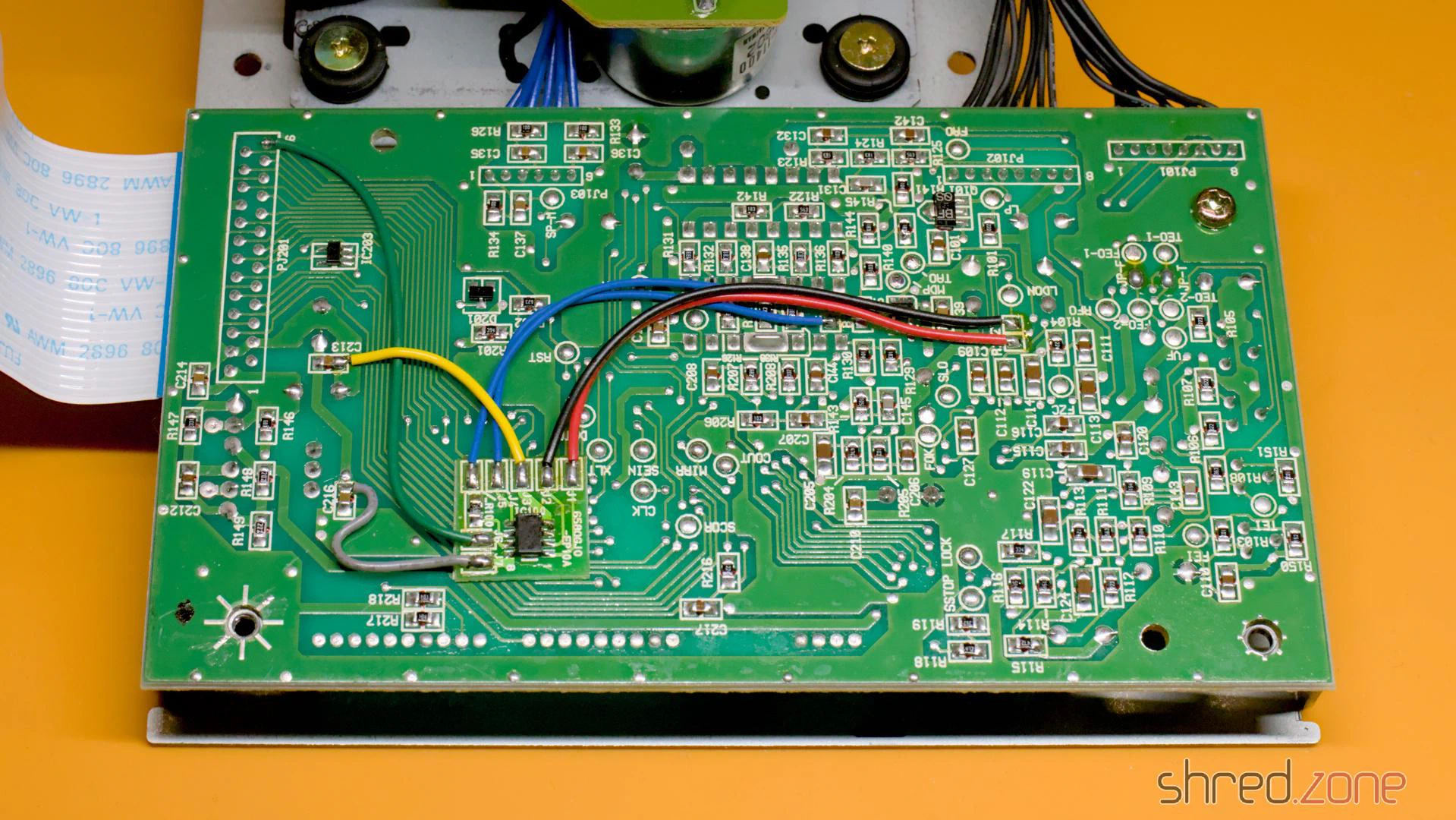
At first I assumed this might be a mod to bypass copy protection measures. However, the CD³² didn’t have a sophisticated copy protection system to bypass. Later I found the answer in a YouTube video: This modification cuts the power supply to the laser and the spindle motor as soon as the lid of the CD drive is opened. However, I could also find many photos of the controller board without the modification. I assume it was a product safety requirement so the CD³² could be sold on the German or European market.
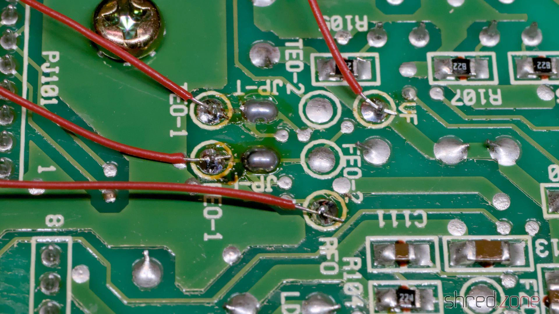
Okay, back to the calibration. As a preparation, I soldered wires to the test points VF, RFO, TEO-1 and FEO-1. I recommend using different colours for this, it makes the calibration easier. Unfortunately, I only had red wire at hand, so I had to check every time which wire went where.
After that, I measured the current settings of the four potentiometers on the controller board and the potentiometer on the laser module with an ohmmeter, and wrote them down. If the calibration should go wrong for any reason, I could restore these settings at any time. A photo of the potentiometer positions would be far too inaccurate, by the way, better to measure!
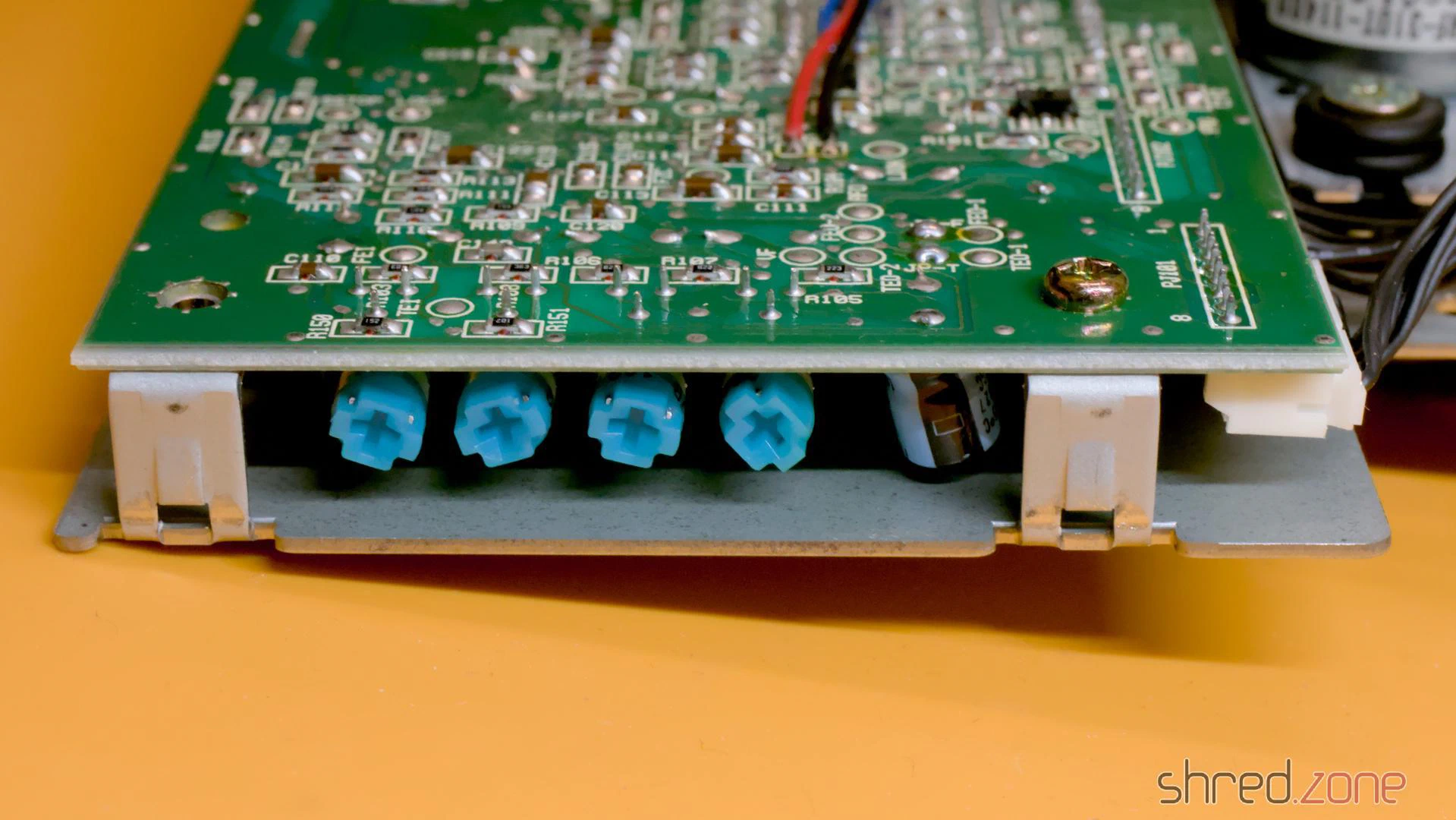
For the calibration, the drive must be reconnected to the motherboard. The top of the case (with the LEDs, the reset button, etc.) must also be connected, as the CD³² does nothing as long as the drive lid is open. The laser unit moves during operation and should have enough space for this.
To hold the CD on the spindle, I removed the spindle clamp from the inside of the lid and fixed the loose part in the middle with a little sticky tape. A magnet holds the clamp to the spindle and ensures that the CD does not slip.
Calibration
The actual calibration process is explained in this blog article by TSB. My attempts to explain it would be far worse. 😉
It turned out with my drive that the process didn’t work like that. After I had carried out the first steps of the calibration, the drive suddenly went on strike and didn’t read anything at all. Fortunately, I had noted down the potentiometer positions, so I could restore the original settings and start over.
Afterwards, I first calibrated the TEB pot until there were about 0 mV between TEO-1 and VF. The drive was still running after that. Only when I calibrated FEB as documented did it strike again. I undid this change and continued with the calibration of the laser power.
WARNING: Be extremely careful with the potentiometer on the laser module and only turn it in very small steps. Otherwise, the laser can be permanently damaged.
There may be a drop of varnish on the pot. It is advisable to turn the pot first while it is switched off to break the varnish, and then use the ohmmeter to reset it to the noted factory setting.
To calibrate the laser power, I connected the oscilloscope to RFO and ground. Then I put a music CD on the spindle and started track 1. The oscilloscope should now show a so-called “eye pattern”:
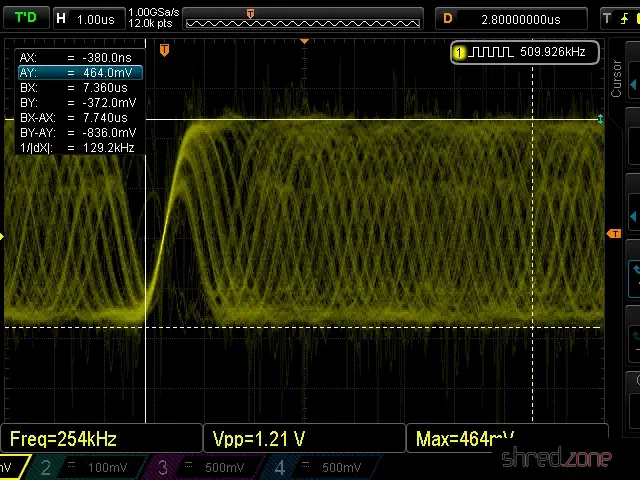
The tricky part is to adjust the pot on the laser module while the CD is playing. I adjusted it very carefully until I reached a peak-to-peak voltage of about 900 mV. 1200 mV should never be exceeded.
Then I adjusted the FEB pot on the controller board until I reached a maximum amplitude in the eye pattern.
The last two pots, FEG and TEG, are calibrated by measuring the test points FEO-1 and TEO-1 respectively against ground. The drive should be playing track 1 of an audio CD and be in pause mode during calibration.
I tried to find the ideal point where the signal on the oscilloscope is as smooth as possible and the correction noises of the laser optics are as quiet as possible. The goal is to find the best possible compromise. You will probably get the best results if you listen to the noises of the laser unit and follow your gut feeling.
The calibration is then complete and the CD³² can be reassembled.
Tip: Burn CD-Rs for the CD³² at the lowest speed your burner supports. This increases the contrast of the data on the CD. Also, prefer CD-Rs that are not transparent when held up to the light.
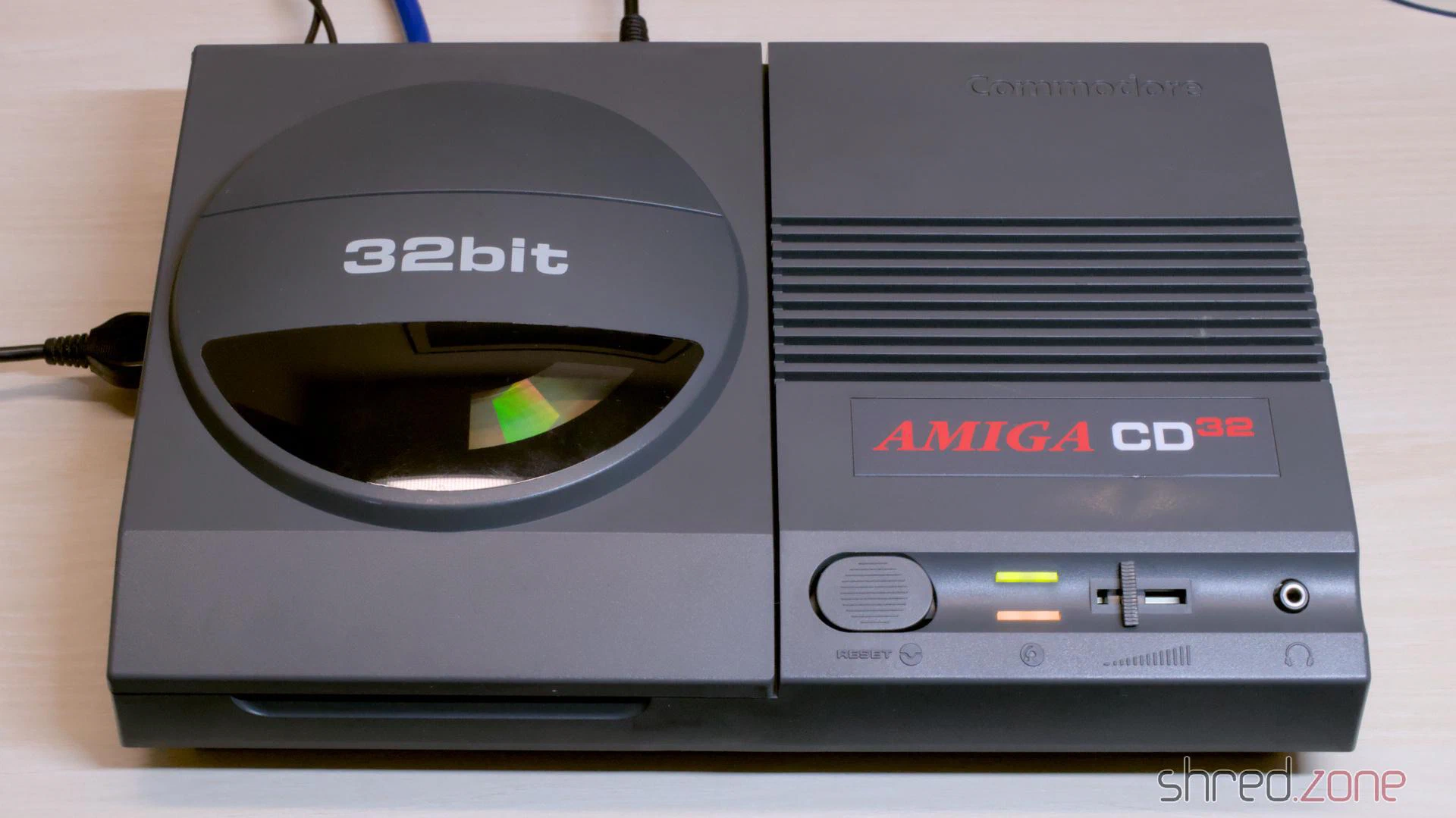
I found this CD³² at a fair price. The machine is still missing from my collection, so I grabbed it. The visual condition of the casing is quite good. There are a few visible scratches. The previous owner tried to touch them up, but only made it worse. At the time, I didn’t suspect that this would be the main theme of the entire restoration.
Together with the games console, I received a power supply and a maths edutainment CD. The power supply wasn’t original, but rather a typical “brick” for external hard drives with a soldered-on CD³² plug. Unfortunately, the gamepad was missing, but luckily I found a practically mint condition Honey Bee Joypad as a replacement a bit later.
Let’s take a look inside.
The Condition
The Amiga was sold as defective because it didn’t display a picture.
The circuit board told me a completely different story. An attempt had already been made to replace the capacitors. After replacing the TH and 100µF SMD capacitors, the attempt was abandoned. Presumably because the picture was gone after that.
I also found several green varnish spots, probably simple nail varnish. It was underneath the replaced SMD capacitors, on solder joints as well as some vias. The varnish made cosmetic sense at best in those places.
And then I found this:
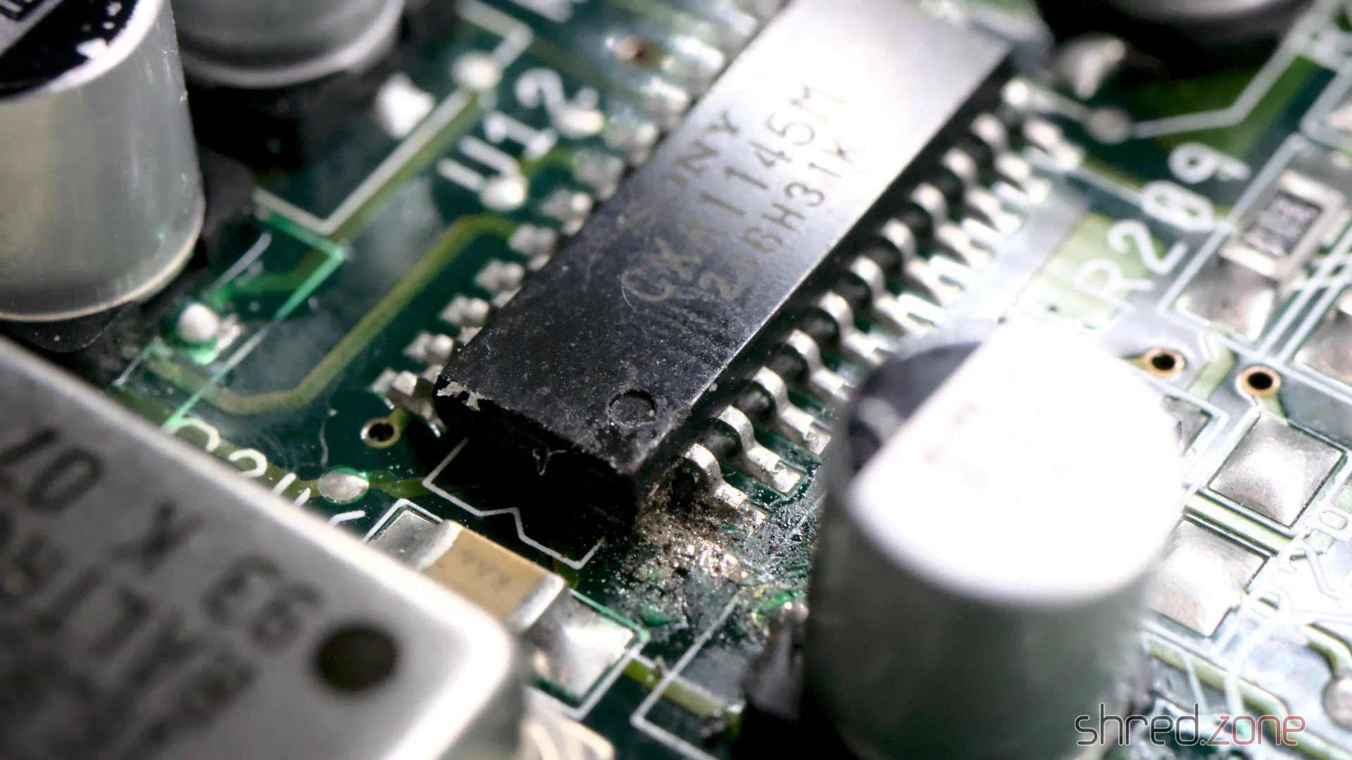
I can only speculate at this point: When the picture suddenly disappeared in the middle of recapping, the previous owner assumed that the video encoder chip was damaged. An SMD chip can only be removed with a hot air rework station, which they probably didn’t have available. So instead they tried to cut the chip off the board leg by leg. Fortunately, they aborted the attempt after just one leg.
Luckily, I didn’t find any further traces of “abuse” on the poor board. It will be enough work as it is to clean up the existing mess.
To be honest, I’m quite annoyed about it. It makes a difference whether the machine simply stops displaying a picture after decades in the cellar, or because someone botched around on the circuit board. The seller should have pointed this out, naturally with corresponding negative effects on the price.
Repair of the Mainboard
At this point it made the most sense for me to restore the picture first. So I replaced the video encoder, as well as an already replaced electrolytic capacitor right next to it that looked suspicious. With that, all visible defects were eliminated. Unfortunately, it didn’t bring the video signal back.
Why did the picture stay black? Were there other faults in the video section, or did the machine possibly not boot up at all?
To find out, I inserted a DiagROM and connected the CD³² to my PC. The DiagROM booted without any problems and logged no errors on the console. Good news: The problem had to lie solely in the video section.
So it was time to tidy up. I removed all electrolytic capacitors, including the ones that had already been replaced. After that, the green nail varnish came off, with nail varnish remover and isopropanol.
On the underside I found a strange solder lump covered by a thick layer of varnish. When I tried to remove it, a telltale fishy smell of leaked electrolyte wafted up. Not a good sign. It meant that a capacitor had leaked and the area wasn’t properly cleaned. I generously removed the SMD parts on both sides in this area, cleaned the board thoroughly and checked the tracks and vias.
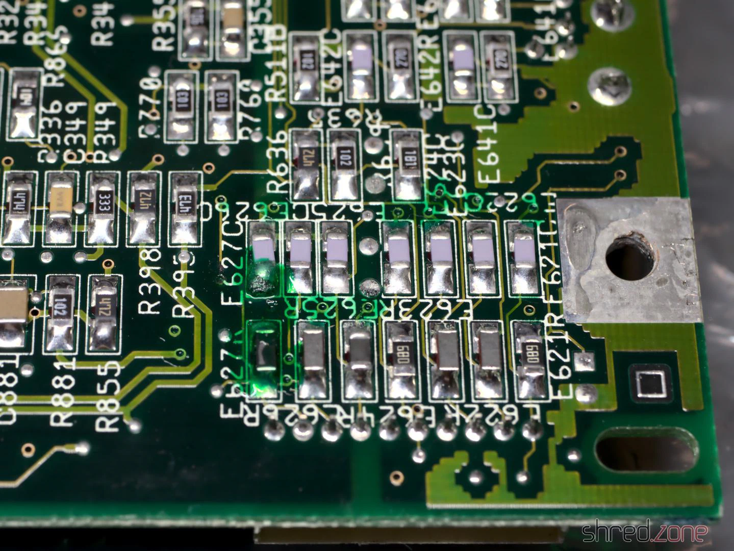
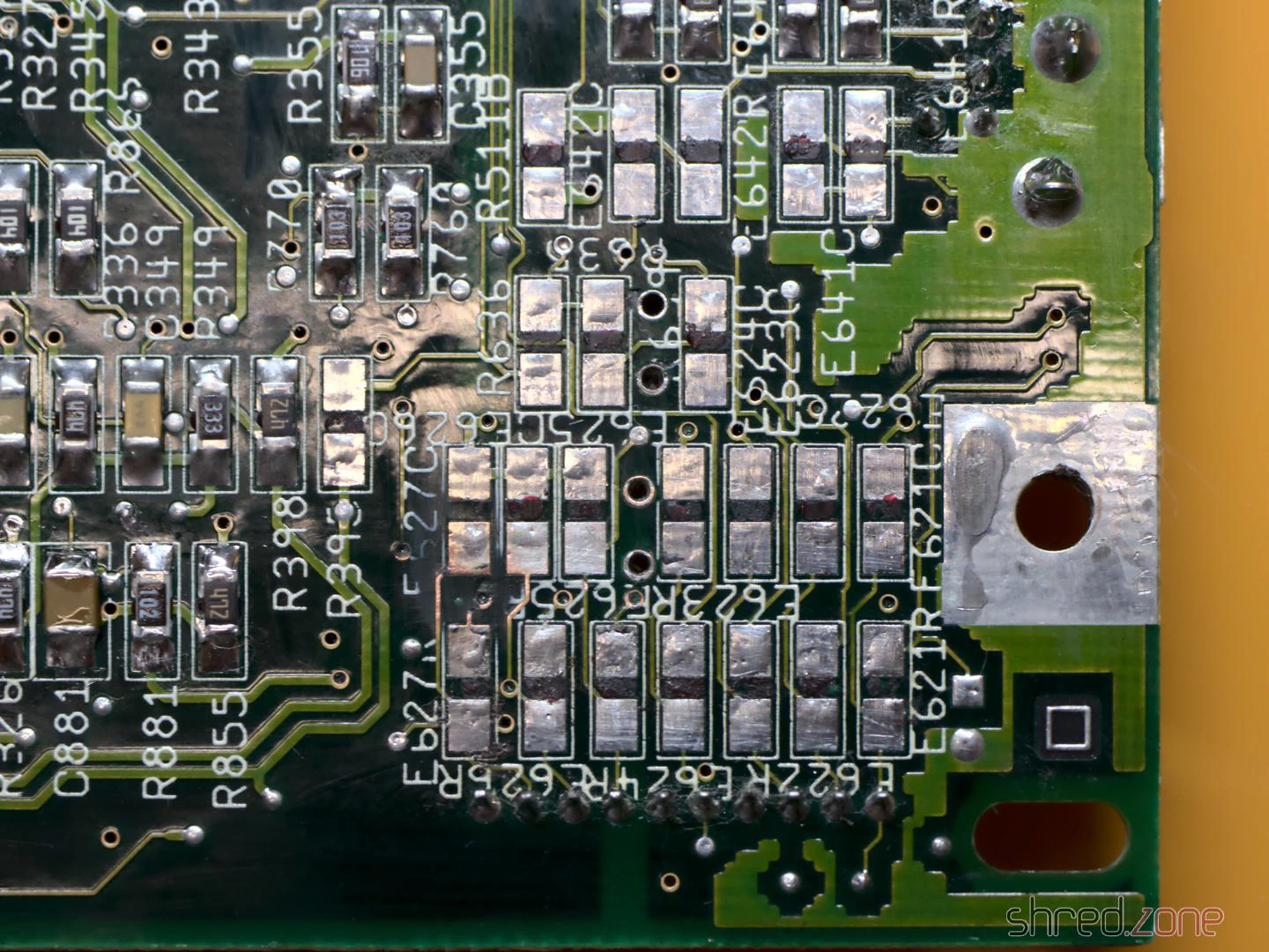
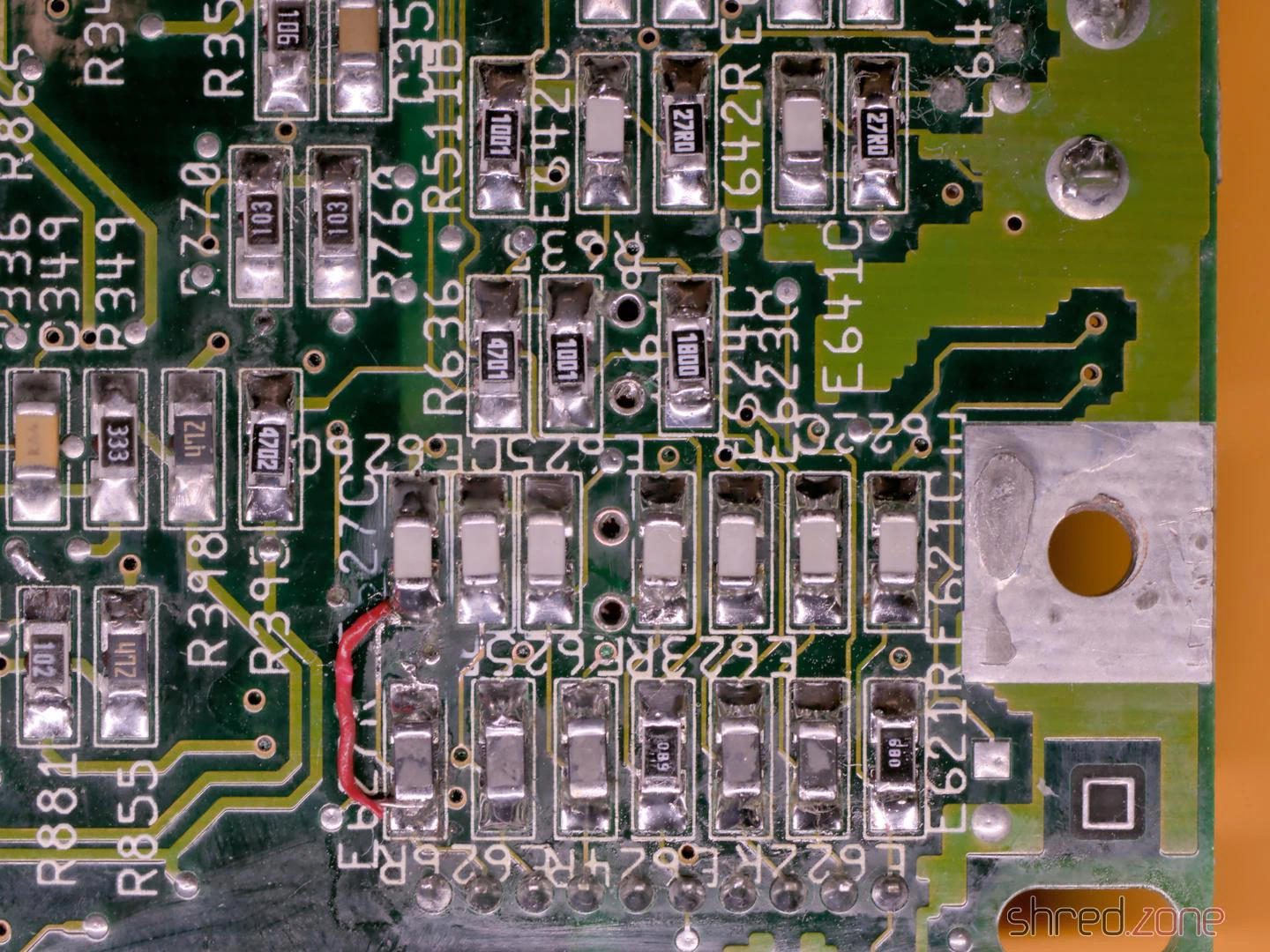
Unfortunately, I tore off a few pads on the 100µF capacitors in the process. I suspect the leaked electrolyte and the thermal stress of two recappings were simply too much for them. Something like this is annoying, but not the end of the world.
Afterwards, I soldered in new components and repaired the torn-off pads with bodge wire. For two SMD capacitors, the board alternatively offered the use of TH capacitors, which suited me very well. Visually, this corner doesn’t look like much anymore, but it should work again.
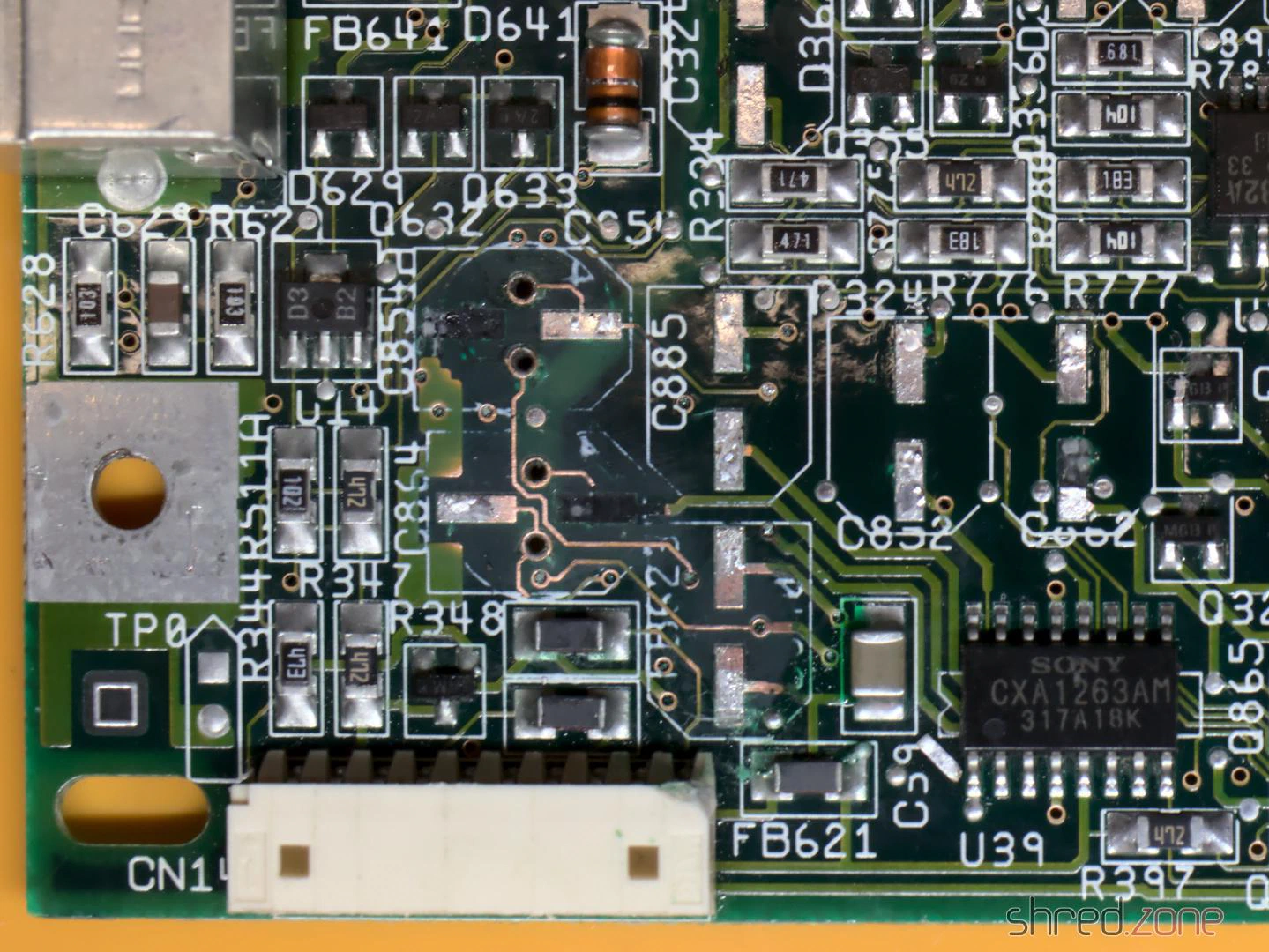
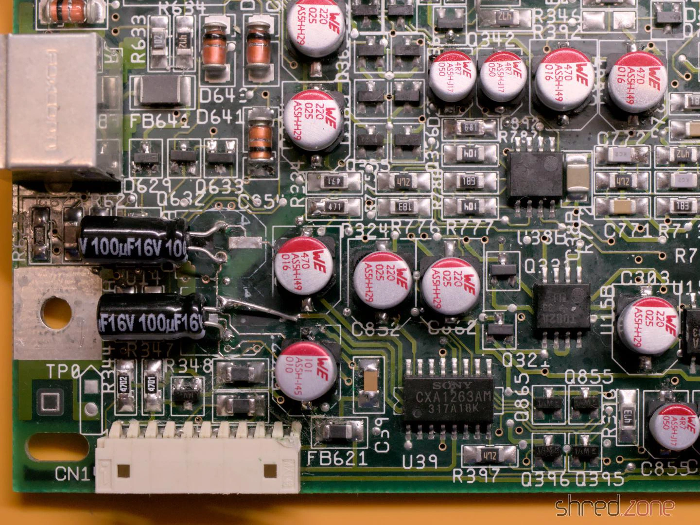
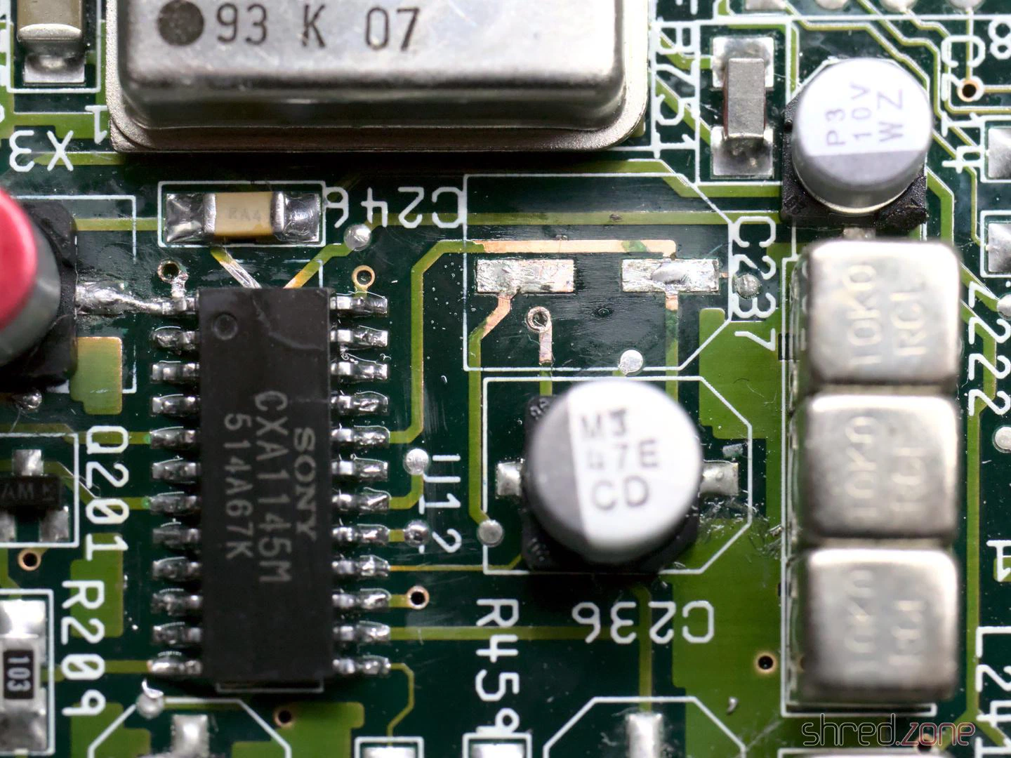
When I buzzed out the tracks and vias on the other 100µF SMD capacitors, I found further breaks at C236 and C237. They carry the luma and composite video signals and would be an explanation for why the picture stays black.
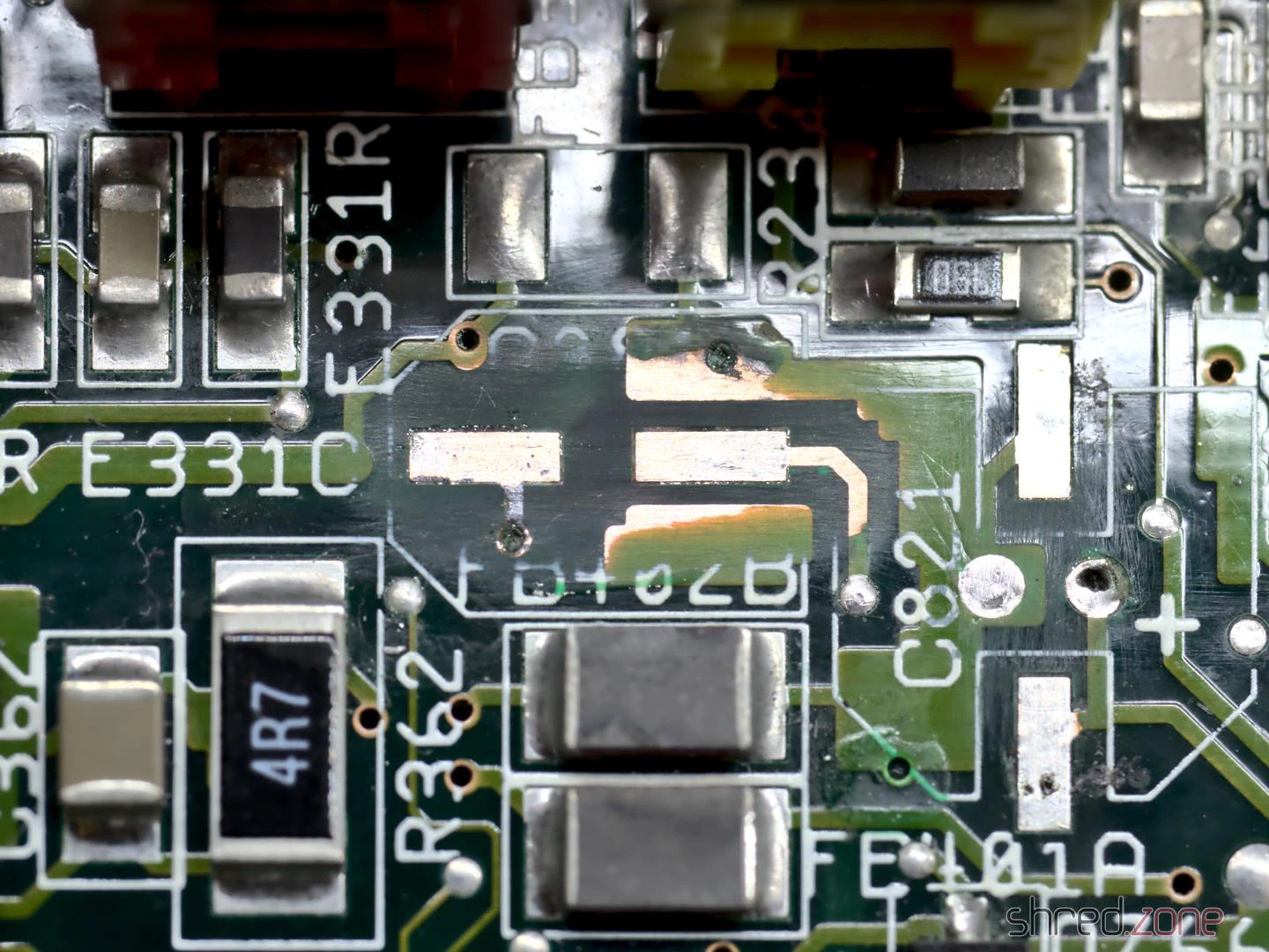
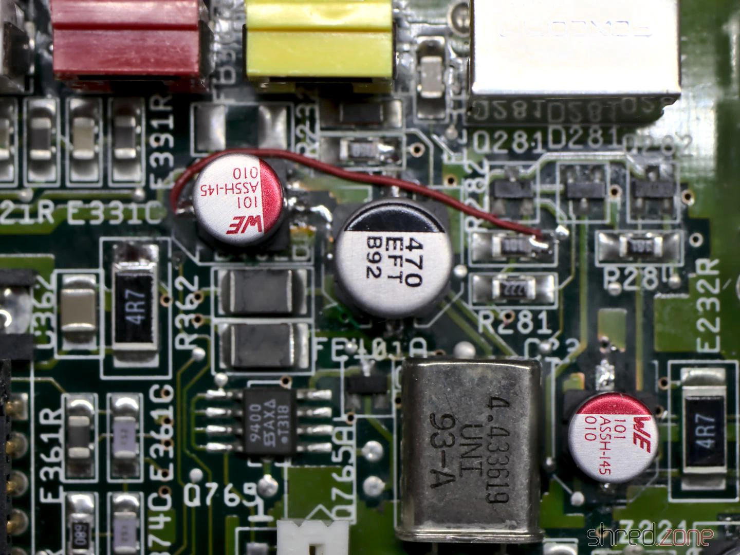
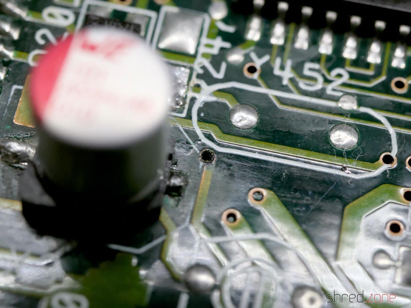
I also found a broken via near C409, which carries the CSYNC signal. As a result, the video sync signal is missing at the outputs. I repaired it by drilling out the via, exposing the connected tracks on both sides, then threading a thin wire through the hole and soldering it to the tracks. (Note: This only works if the via has no connection to one of the inner layers of the board, which was the case here.)
Overall, there were several reasons why the machine no longer showed a video picture.
By the way, two TH capacitors on the board have a peculiarity. At C408 and C811, the silkscreen shows the positive pole on the wrong side. This led to even Commodore soldering the capacitors in the wrong way round from the factory, which is why you will find quite a few CD³²s with bulging capacitors in this spot. I decided to solder in SMD capacitors there too, which can be soldered in as shown on the silkscreen.
So, power on, and to my surprise the Amiga worked again.

I checked all video and audio outputs and found a signal everywhere. The machine also ran stably. The mainboard was thus repaired and overhauled.
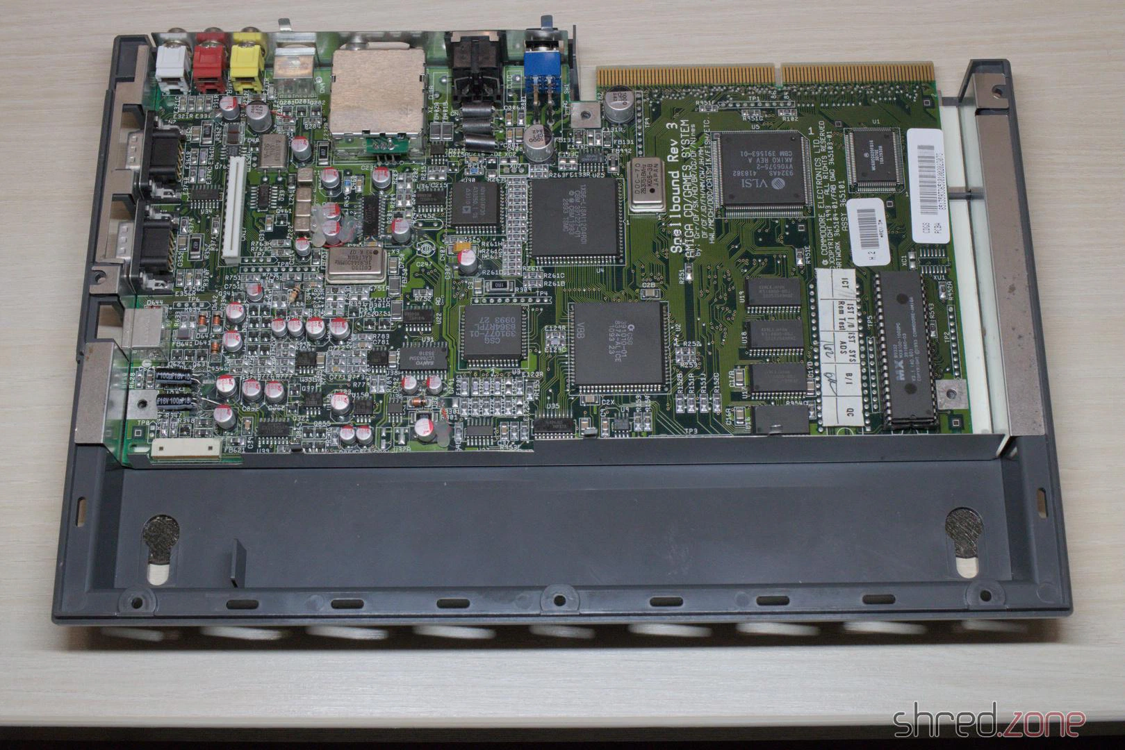
Even though it was an unexpectedly difficult affair, I am glad that I was able to repair the machine.
In the next part I will replace the laser module and calibrate the CD drive.
However, they were quite inconvenient. Cassettes were slow. It took several minutes for a game to load. With a “collection” of several games on one cassette, you first had to fast-forward to the right spot, which wasn’t that easy, as the noise of the data stream sounds pretty much the same to us humans. You could write down the counter readings on the cassette recorder, but the counters weren’t standardised, making the index tied to a specific model.
When I finally got my Amiga with a floppy disk drive, I quickly forgot the times when I had to fiddle with cassettes.
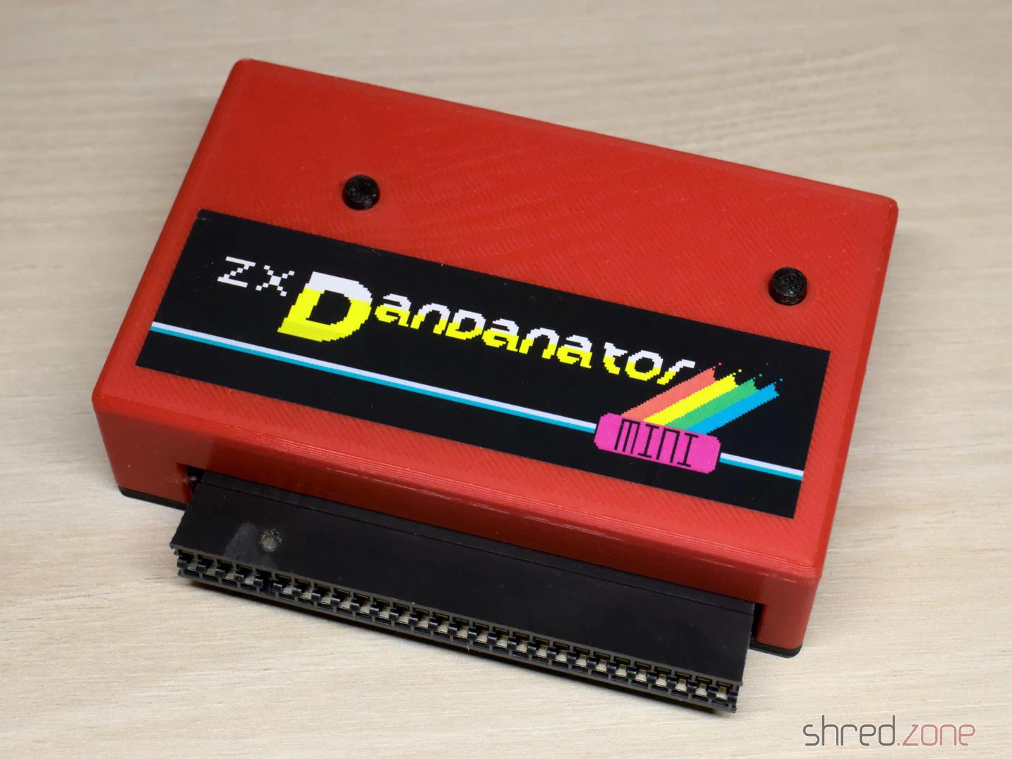
Today I own a few ZX Spectrums, but no cassette recorder anymore. To load software into the computer, I usually use my PC’s headphone jack and tzxplay. But there is a more elegant way. The ZX Dandanator Mini by Dandare is an expansion with 512KB of flash memory where your favourite games can be saved. A boot menu allows you to select one of these games. It is then loaded directly into memory. The Dandanator also offers a Kempston-compatible joystick port.
While assembling my ZX Dandanator Mini, I noticed that the project’s documentation left a few questions unanswered. I hope my blog article will help others with building their own.
Parts
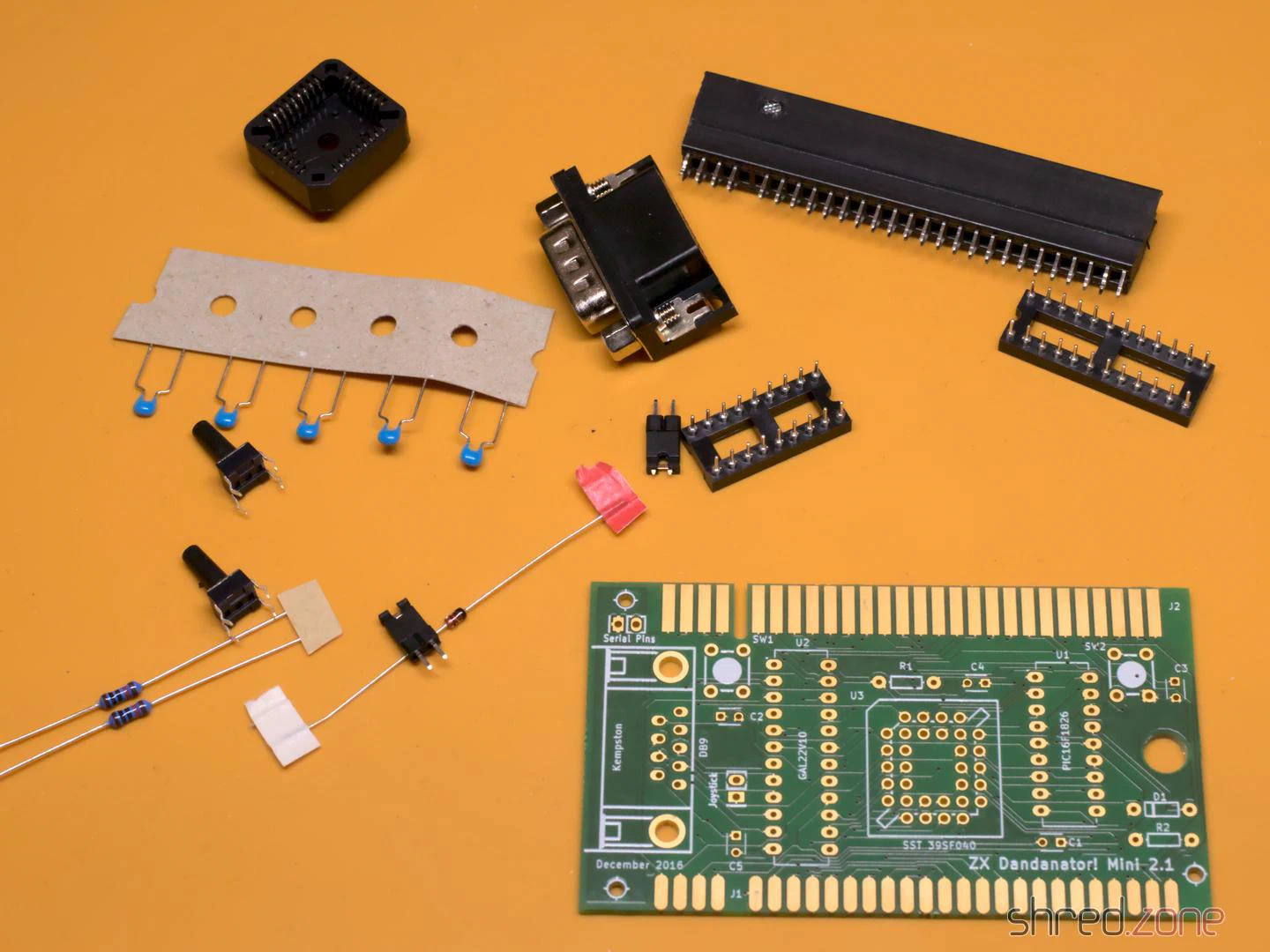
- 1x GAL 22V10 (+ DIP20 socket)
- 1x PIC 16F1826-I/P (+ DIP18 socket)
- 1x SST 39SF040 Flash ROM (+ PLCC32 socket)
- 1x 1N4148 (TH)
- 2x 10kΩ resistors (TH)
- 5x 100nF ceramic capacitors (TH)
- 1x D-Sub connector, 9-pin male, angled, European style (e.g. this one)
- 2x pin headers, 2-pin
- 1x jumper
- 2x tactile switches, 6 mm high (17 mm for the 3D-printed case)
- 1x PCB (Gerber files are here)
- 1x ZX Spectrum Edge Connector (can be found in retro shops, online marketplaces, or DIY)
- 1x 3D-printed case (optional)
You need a programmer capable of flashing the PIC, the GAL, and the Flash ROM (e.g. the XGecu TL-866II Plus with PLCC32 adapter). I also recommend a good PLCC extraction tool.
Classic GALs are no longer produced, but can still be ordered as NOS parts on online marketplaces. A replacement that is still being produced is the Atmel ATF22V10C-10PU. However, you will then additionally need a 3.3kΩ 6-pin resistor network (more on this below).
Assembly
The assembly is straightforward. You start with the flattest components and work your way up to the tallest ones. There are no SMD components, so even a soldering beginner shouldn’t have any problems.
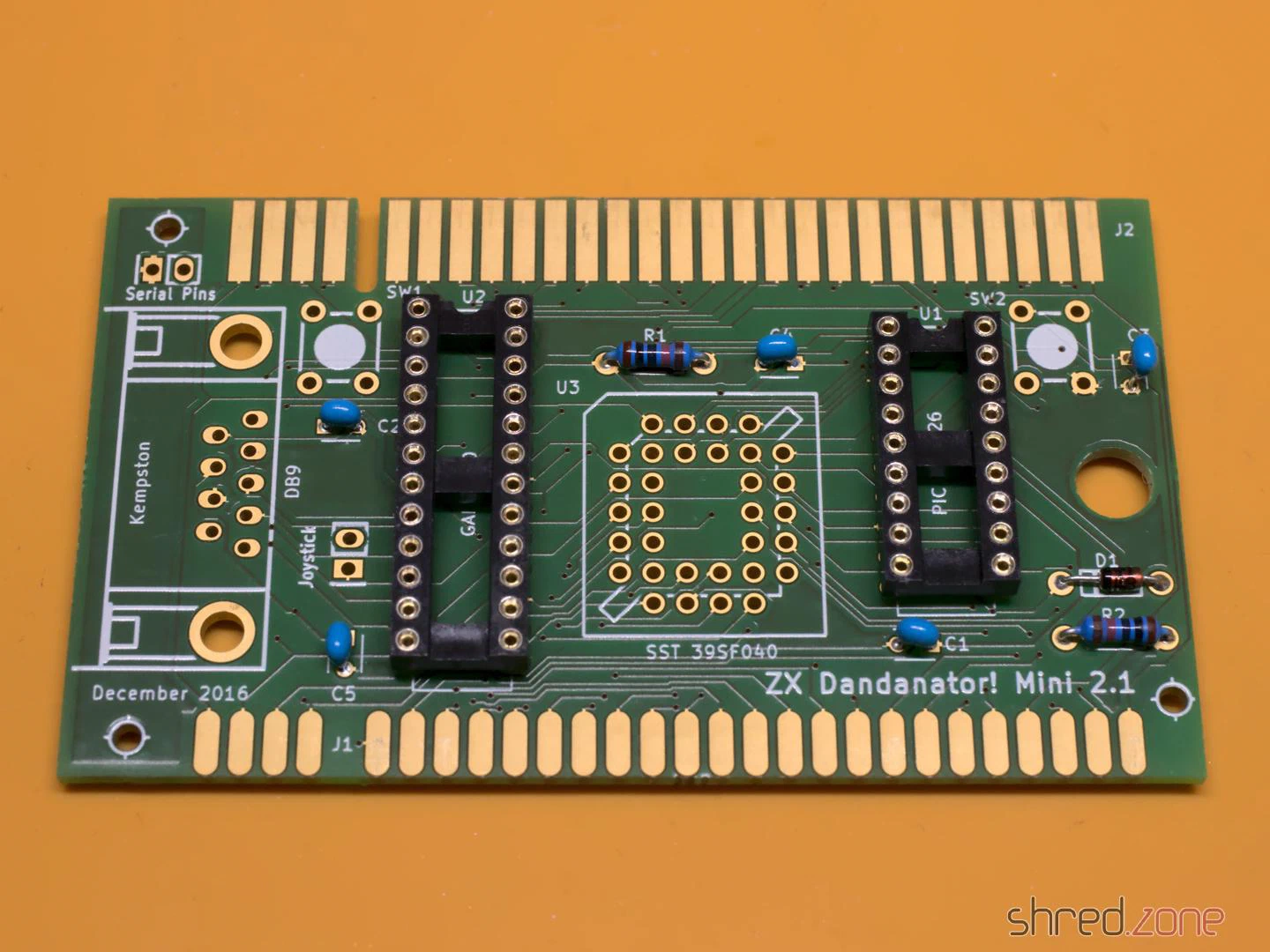
Make sure the sockets are aligned correctly. Unfortunately, there are no markings for pin 1 of the two DIP sockets on the silkscreen. They should be aligned with the notches facing towards the buttons, as seen in the photo. The PLCC socket should match the outline on the silkscreen.
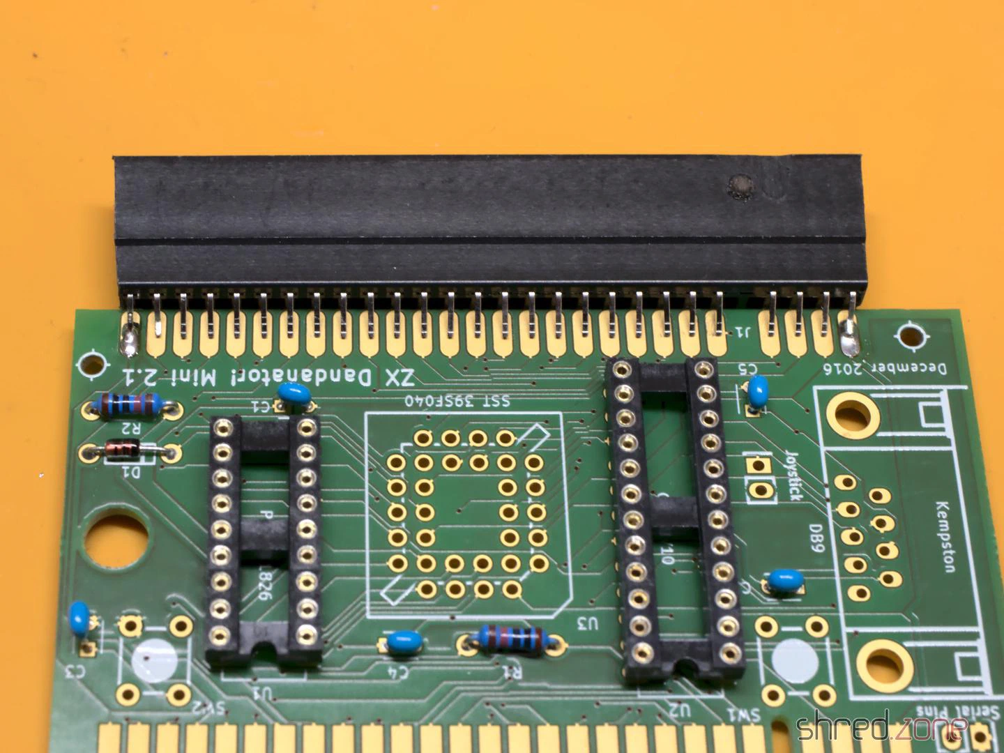
The edge connector is normally meant to be soldered upright, not to the edge of the PCB. So the pins must first be bent inwards on both sides until the connector sits centrally and all pins touch the pads of the PCB. Also, make sure to solder the connector to the correct side of the PCB; that’s the one with the short pads. The connector on the other side is intended for further expansions, such as a joystick interface, but you could even stack several Dandanators together.
If you intend to use the 3D-printed case, leave a gap of about 2 mm between the PCB edge and the connector.
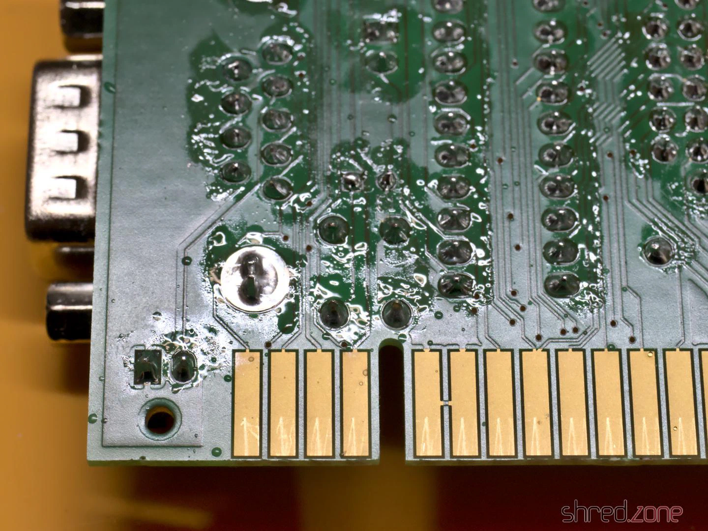
Some of the pads are close to the edge connector on the back. It’s easy to accidentally spill a few drops of solder onto the pads while soldering. A piece of Kapton tape can easily protect them.
One problem with the ATF22V10C is that it doesn’t have internal pull-ups on the inputs. This means the inputs float when no joystick is connected. This causes problems. On my system, the first game in the list was always started immediately when no joystick was connected. A possible solution is to solder a resistor network onto the bottom side. The resistors are connected to pins 8, 9, 10, 11, and 13 of the ATF22V10C. The common bus is soldered to pin 24. Be careful not to bridge or short-circuit adjacent pins.
This problem shouldn’t occur with the ATF22V10B, but at the time of writing, this variant was either sold out or absurdly expensive.
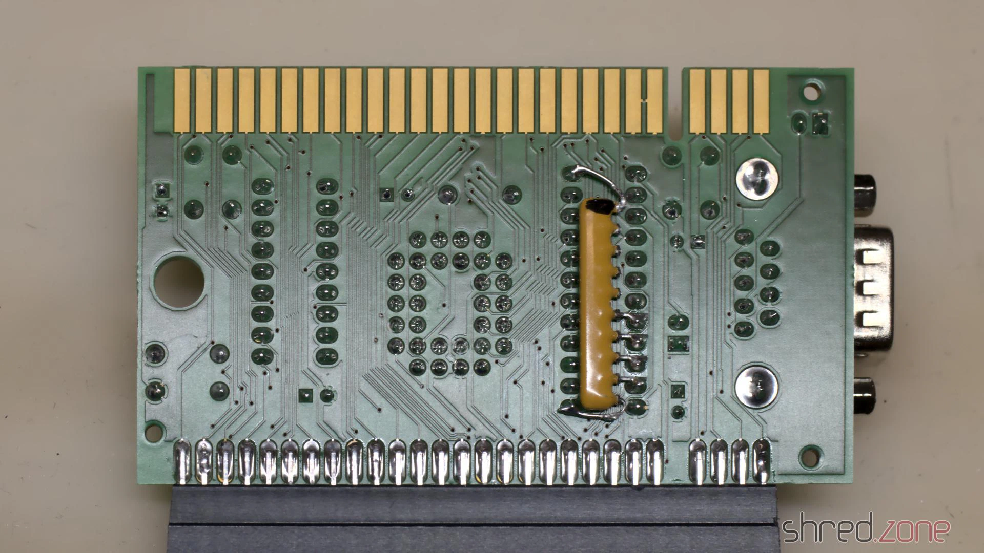
Although this problem probably doesn’t occur with older GALs, the manufacturers still recommend not leaving input pins floating. In my opinion, the pull-up resistors should have been part of the Dandanator design.
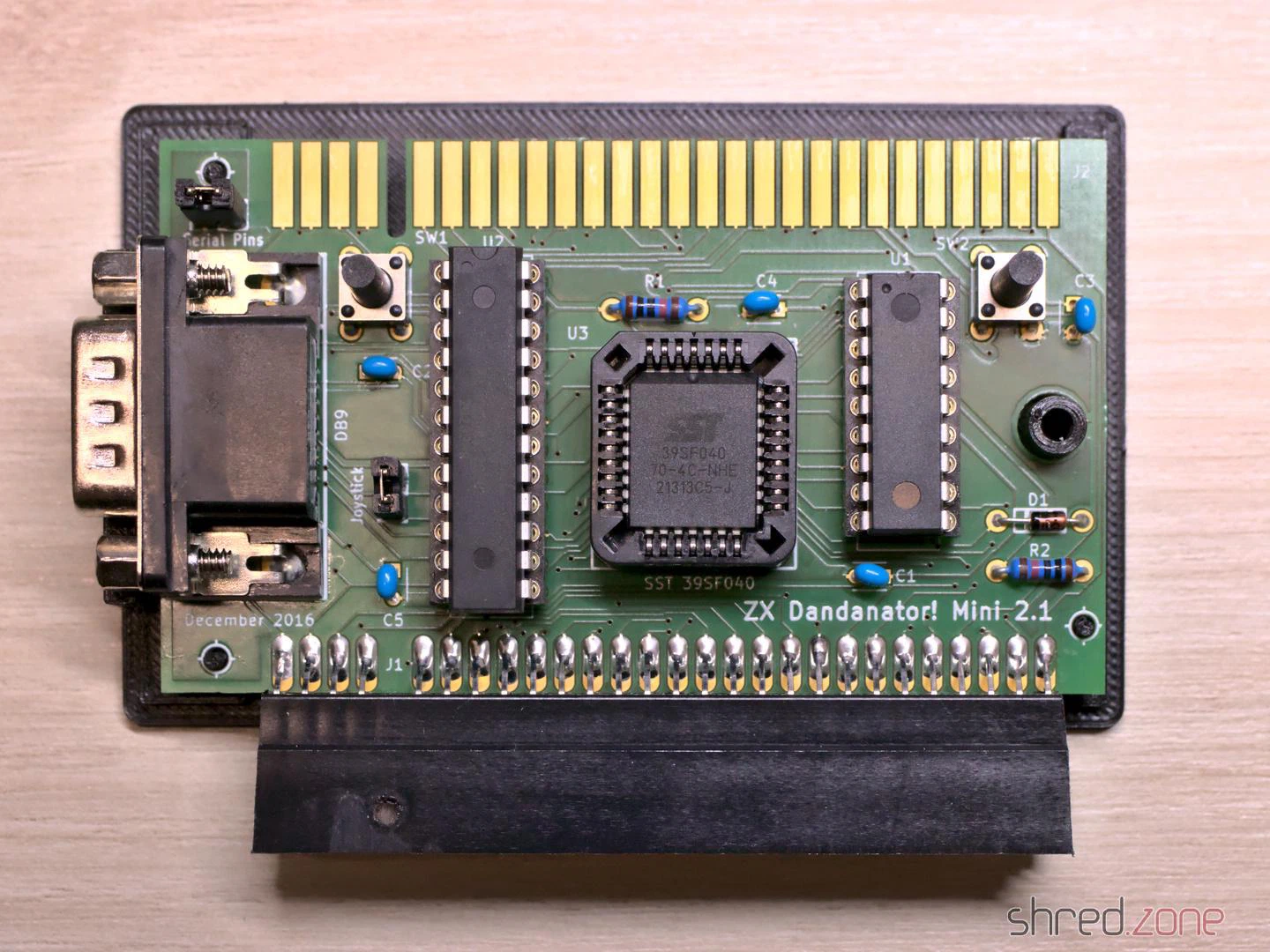
In the final step, you clean the PCB and check it for solder bridges and other faults. A short circuit can destroy the voltage regulator in the ZX Spectrum, which is relatively difficult to repair.
The “Joystick” jumper is there to activate the joystick port. It should be closed if no other joystick interface is used. The “Serial Pins” jumper seems to be intended for in-circuit programming and should not be closed. (Nothing will break if you accidentally close it, but then the joystick will be permanently pressed to the right.)
Once the assembly is complete, the next step is to program the chips. They are all programmed differently.
Flashing the chips
- GAL: The fusemap can be downloaded here. If you are using an ATF22V10 and the XGecu programmer, make sure you select the
(UES)variant as the chip type. - PIC: An initial firmware can be downloaded here. I tried flashing it with the minipro software, but couldn’t get a working PIC this way. Ultimately, I used the original software from XGecu.
- Flash ROM: The Flash ROM contains the games and also pokes. The image file is generated by a ROM Assembler tool.
The ROM Assembler is written in Java, so it runs on every modern operating system. If you know your way around Java, you can easily compile the latest version yourself from the source code. You can also download a jar file from the Dandanator download page and run it using the command java -jar dandanator-mini-*.jar.
The GUI of the ROM Assembler is fairly self-explanatory. You can simply drag and drop TAP, SNA, Z80, and POK files of your favourite games into it until the flash memory is full. In the settings, you can change the font and language, and even use a custom background image.
Many games can be found at World of Spectrum. An extensive collection of POK files is available here.
Once you have put together your favourite games, create a ROM image and write it to the Flash ROM.
Let’s play!
The Dandanator is connected to the ZX Spectrum’s expansion port. Remember to unplug the computer from the power first.
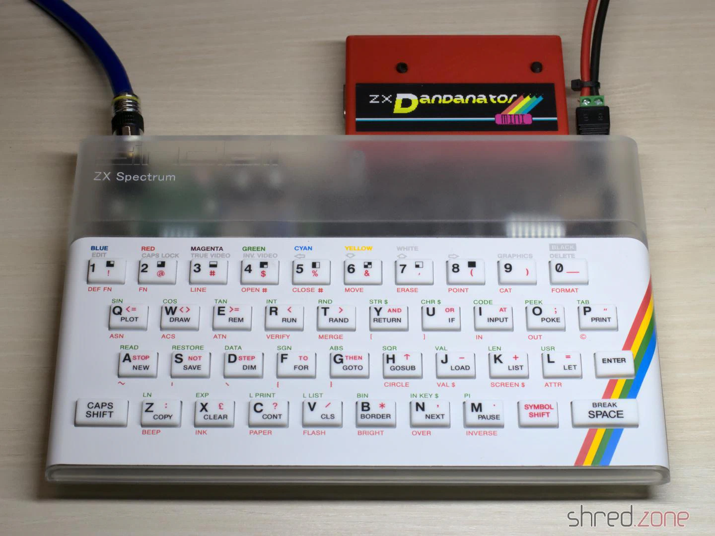
Now switch on your Speccy and press the right button on the Dandanator to reach the main menu.
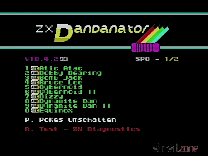
You can select a game, either by using the joystick or pressing the corresponding key, then select the pokes to apply, and finally start the game.
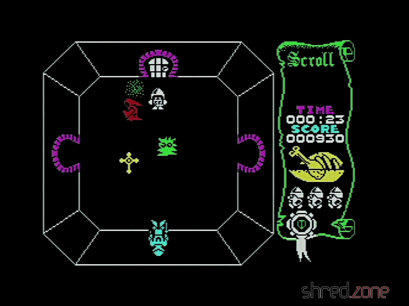
When using the Dandanator for the first time, you should turn the Speccy off, then hold down both buttons and turn it back on. The Dandanator will then flash the latest firmware version to the PIC.
The right button always takes you back to the main menu. The computer no longer needs to be reset.
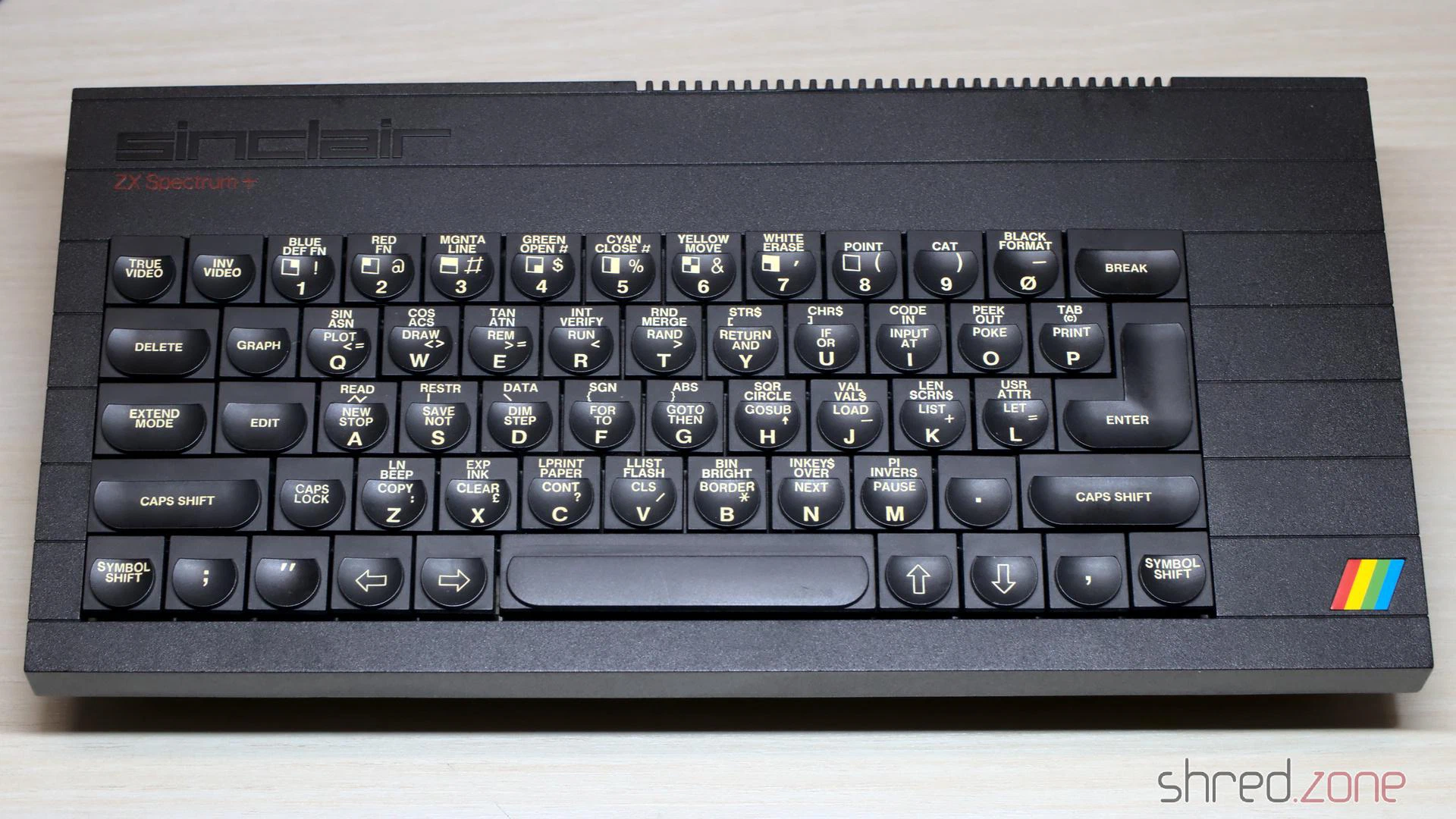
Let’s take a look inside a ZX Spectrum Plus. Basically, it’s the same as a ZX Spectrum, but with a (slightly) better keyboard and a reset button. However, this machine here held a few surprises.
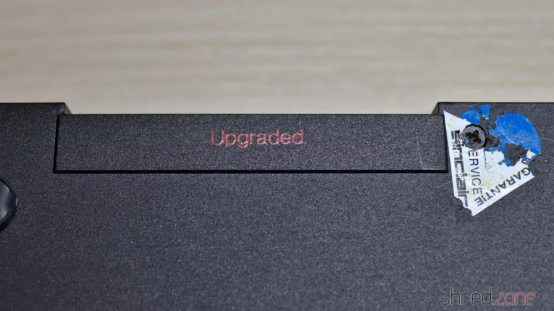
The first surprise was that instead of a serial number, the word “Upgraded” was stamped into the case. Next to it was a (damaged) warranty seal from Sinclair Germany. I didn’t know that Sinclair had sold upgrade packages for the ZX Spectrum.
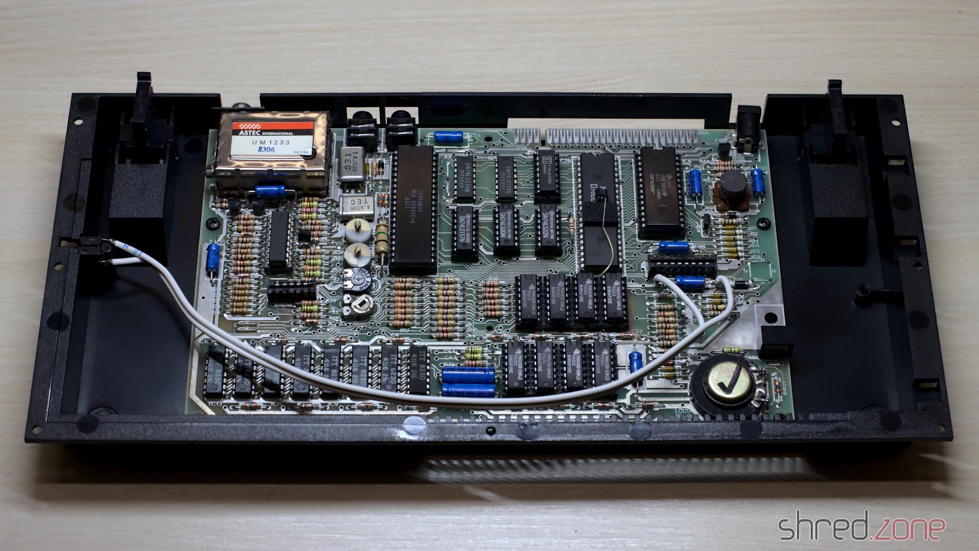
Inside the case, I found an Issue Two board, which is a rare sight in a ZX Spectrum Plus. For an obvious reason: the Issue Two heatsink is too large for the Plus case, it only fits in at a very awkward angle.
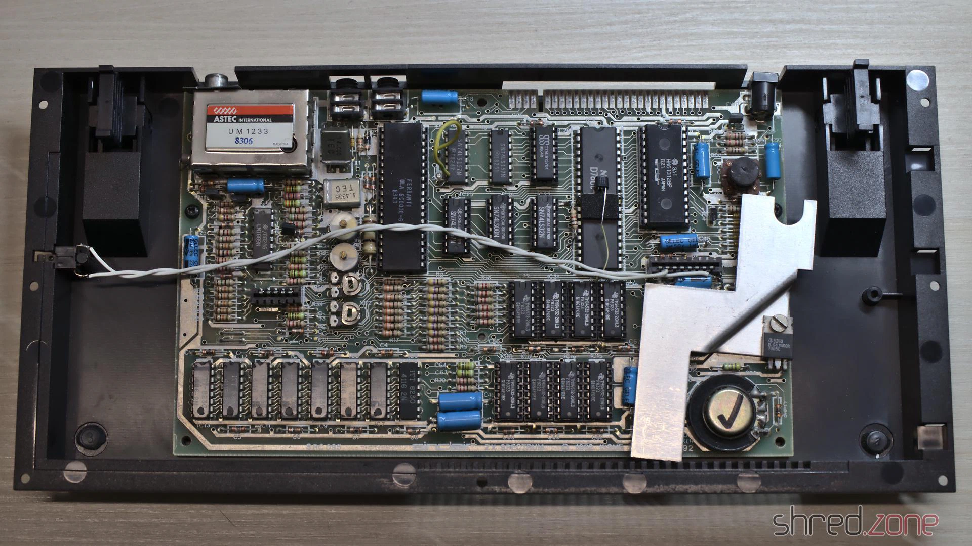
I will replace the 7805 with a DC/DC converter anyway, so the sight of this twisted heatsink will disappear too.
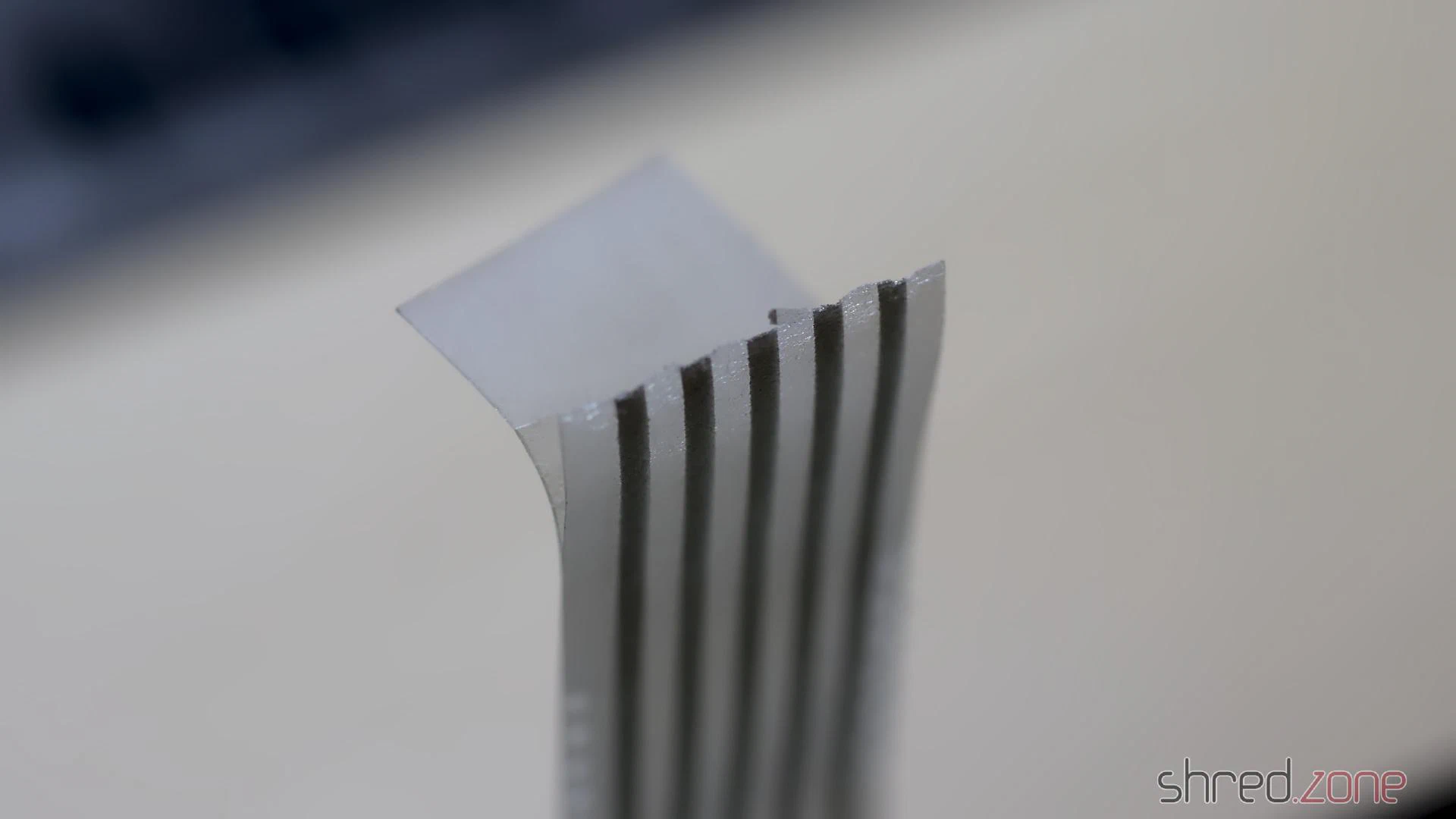
I also noticed that the keyboard membrane had become brittle over the years and had to be replaced with a modern replica.
Technical Check
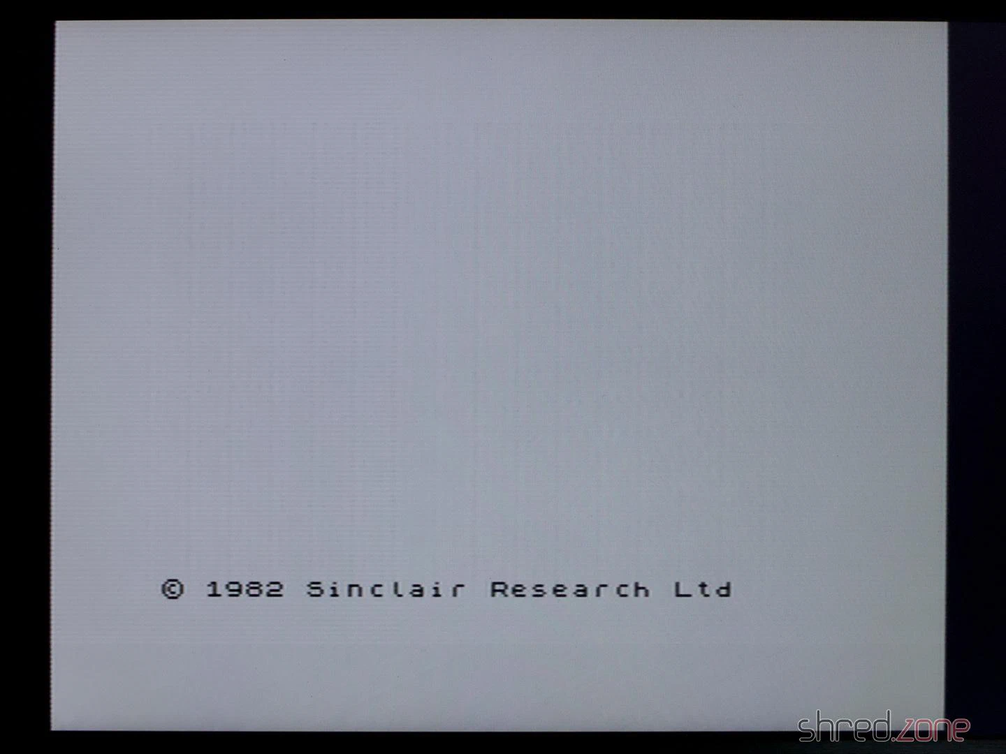
The very first thing I do is the Composite Mod. It only takes a piece of wire and a few minutes with the soldering iron. It’s always worth investing the time, even if the Speccy turns out to be beyond repair later. However, a first check showed the start screen, so everything seemed fine at first.
Then I plugged in the diagnostic module, and the trouble began.
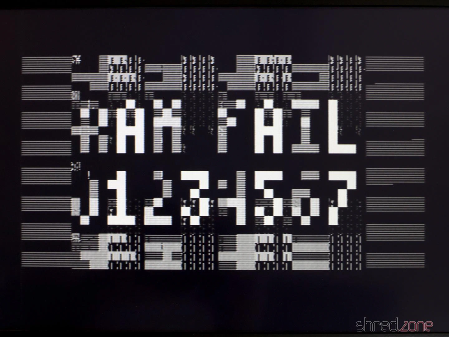
The diagnostics reported that all eight lower RAM chips were faulty. The LEDs on the module showed that -5V and 12V were missing. A voltmeter confirmed that -5V had failed and only 7V was present on the 12V line. So the voltage converter seemed to be faulty. I found it strange: when I unplugged the diagnostic module, the system started up again, even though both voltages were still missing.
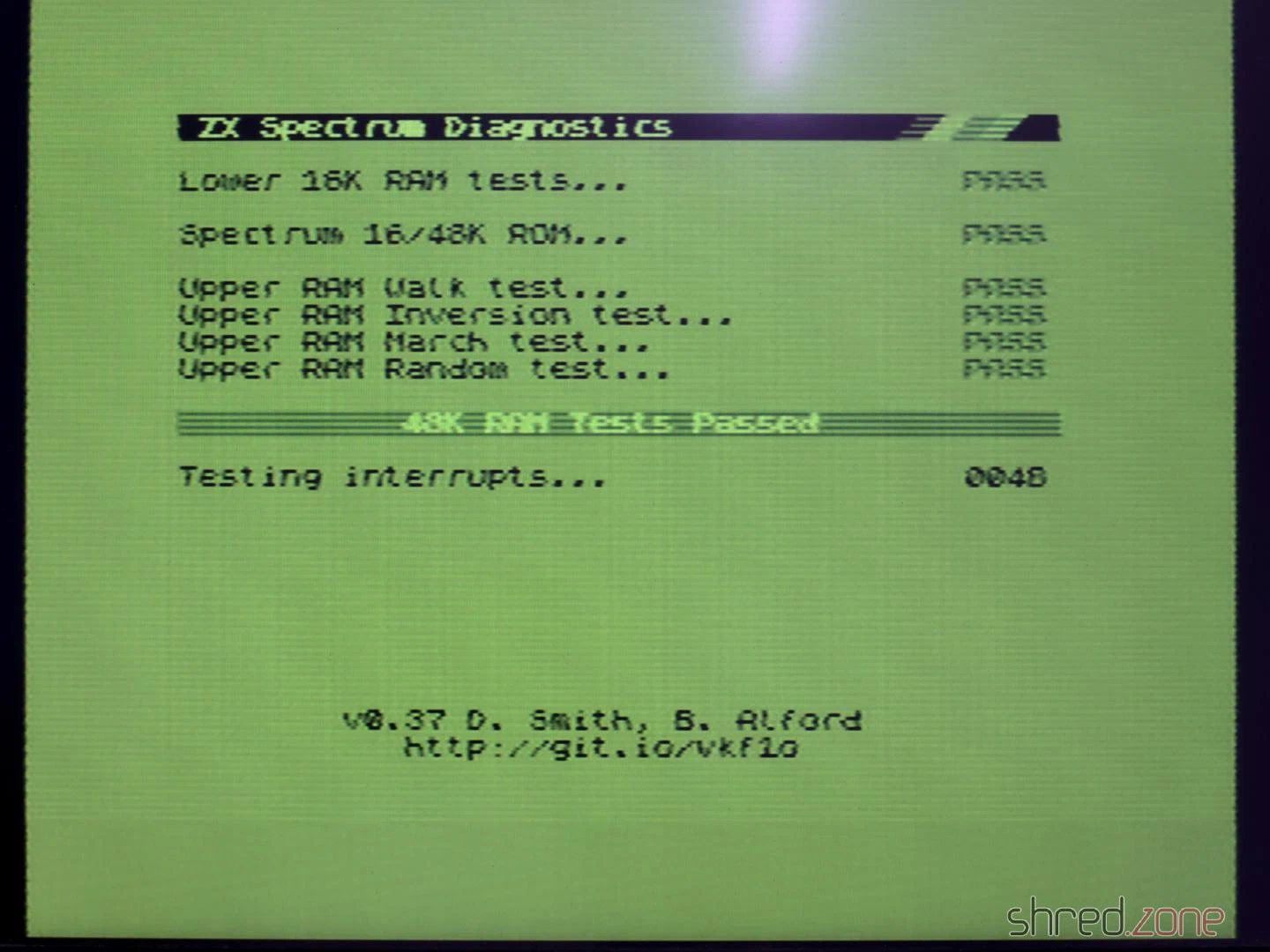
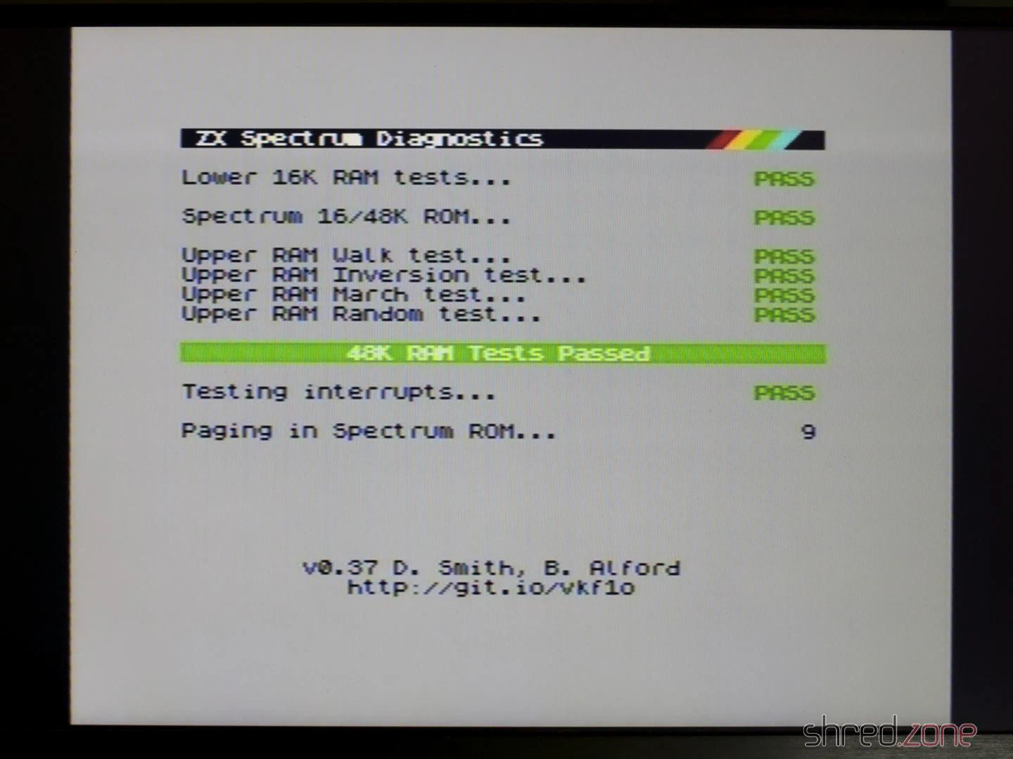
I checked the coil, but it had no short circuit between the windings. So I replaced the usual suspects of a faulty voltage converter: TR4, D15, and D16. I also replaced the 7805 with a DC/DC converter as planned and renewed all electrolytic capacitors. The -5V and 12V were fine after that, and all diagnostic tests were passed.
The repair wasn’t successful, though. Because now the screen had a strong green tint, the colours were pale, and there were visible horizontal lines.
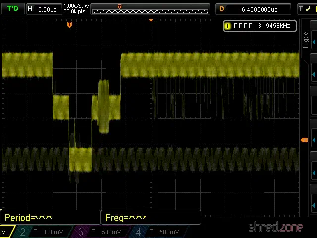
On Issue Two boards, there are two potentiometers for calibrating the white balance. You just need to connect an oscilloscope to the composite line and then adjust both pots until the signal noise is reduced to a minimum. But I could only slightly improve the green tint; it didn’t disappear completely. The annoying horizontal lines remained as well.
That was the best I could get out of the signal. And that is pretty dismal.
Why was the white balance perfect before I repaired the voltage converter? I found out that the 12V is necessary for generating the colour signal. Because of the faulty voltage converter, the 12V was missing, and so the image was displayed in monochrome. But since the start screen doesn’t use colours anyway, everything seemed fine. After I repaired the 12V, a colour signal was generated again, and the image suddenly got a colour cast.
I initially suspected the ULA, but the problem persisted when I swapped it for a working one. Then I swapped the LM1889N. The strange horizontal lines disappeared, and the colours got a bit better too, but still not perfect.
I still couldn’t set a clean white with the pots. Then I noticed that pot VR1 wasn’t working very well and crackled when adjusted. So I replaced it with an encapsulated one from Piher that just about fitted. After that, I was finally able to calibrate the signal so that it had minimal noise. Still not perfect, but good enough.
The result was a picture with a good white balance, where the passed diagnostic tests were the only green things.
As a test, I reinstalled the previous LM1889N again, and the colour problems as well as the horizontal lines returned. So the green screen problem was a combination of a faulty LM1889N and a faulty potentiometer.
The hardware part is finished. Let’s look at the keyboard next.
The Keyboard
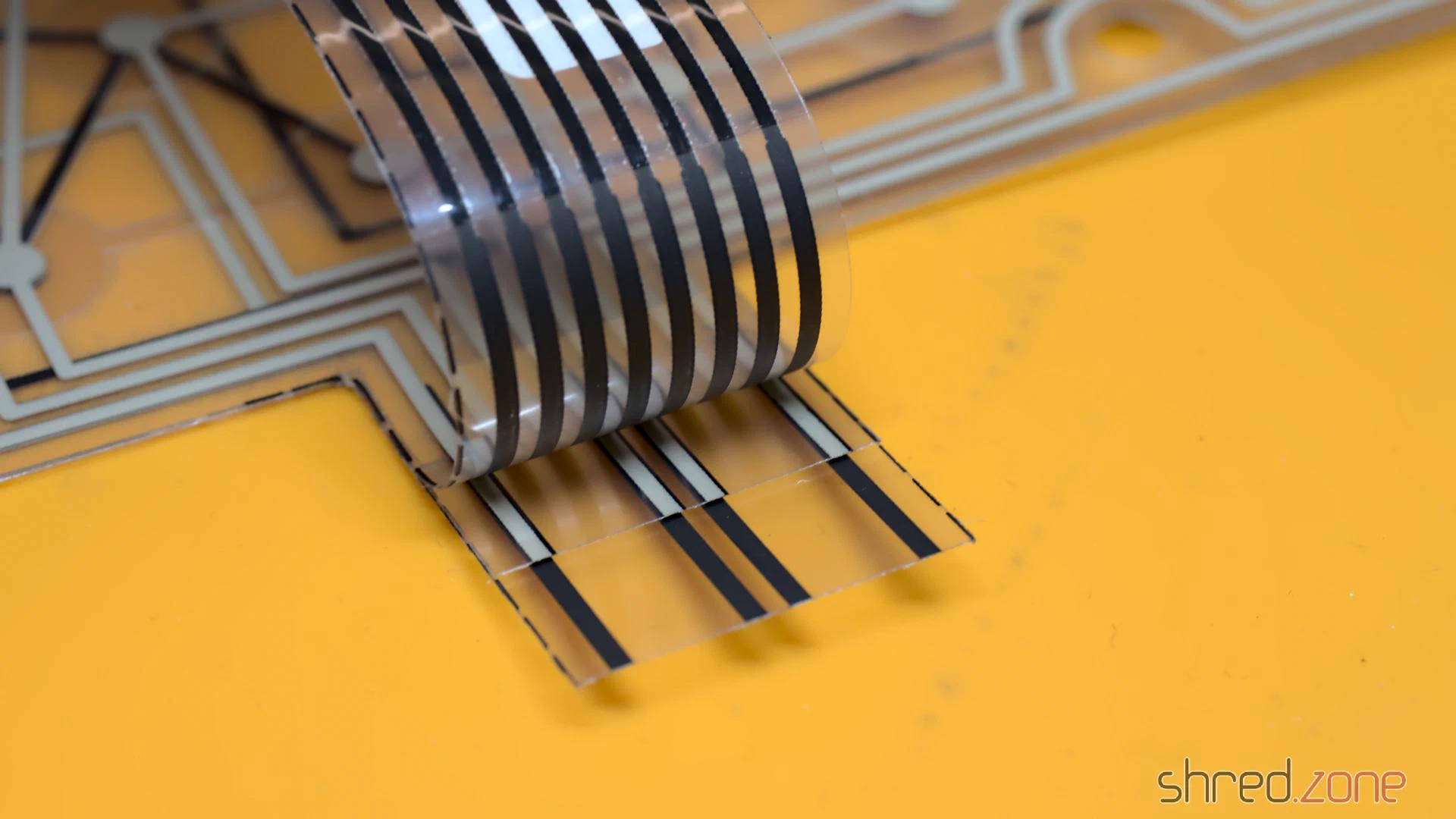
The ZX Spectrum Plus keyboard is a bit special. On the connection side, there’s no difference to the ZX Spectrum keyboard. However, the ZX Spectrum Plus has a few more special keys, like cursor keys or a dedicated delete key. These keys have to perform two key presses simultaneously and in the correct order. This is achieved by two interconnected membrane layers. A key press then closes the contacts on both layers.
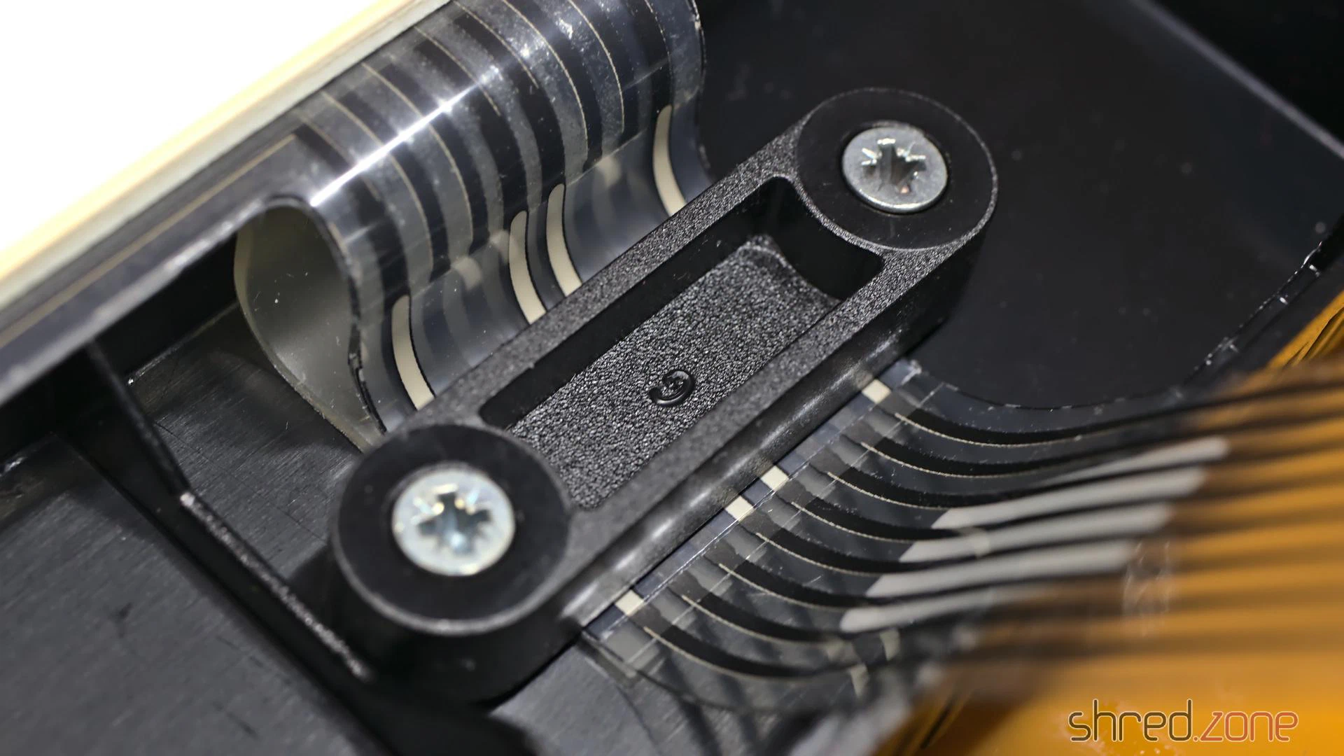
These layers are connected to each other at the top end of the membrane connectors. So it is important to work precisely at this point and make sure that the layers are correctly aligned and securely fastened under the brackets. Please don’t tighten the screws too much, the plastic is almost 40 years old. 😉
After a thorough cleaning, I was able to reassemble the machine.
And that’s it. Now I finally have a ZX Spectrum Plus in my collection too.
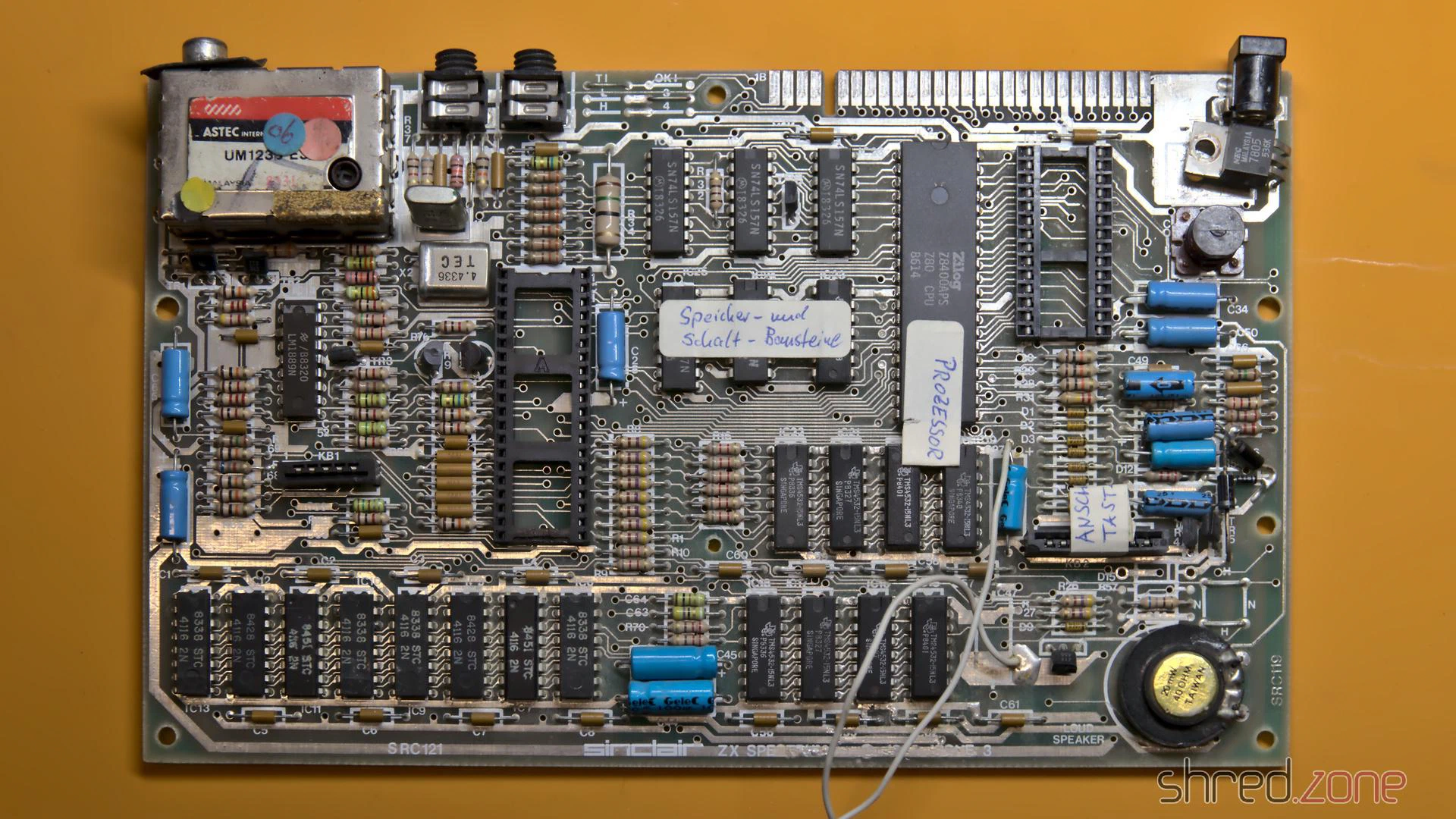
For testing, I plugged in the diagnostic module, but the computer didn’t even start with it and the D0 LED stayed permanently dark. There had to be a short circuit somewhere on the data bus.
That wasn’t too bad, because I plan to build a completely new ZX Spectrum for myself anyway. I want to use as many new components as possible. Only the ULA, the CPU, the LM1889N, the coil and the RAM chips will be reused, as they are no longer manufactured and are correspondingly precious.
So I first removed everything valuable. The scavenged original board was quite a sad sight, but the prospect of a brand new Speccy emerging from it made it less painful.
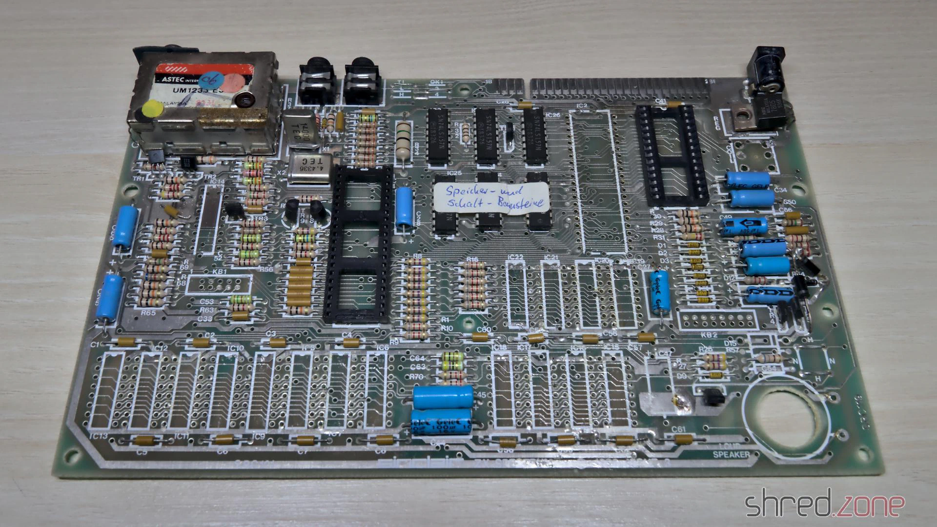
I already checked the ULA in another Speccy, it was fine. Unfortunately, out of the 16 RAM chips, only nine passed the tester. That was much less than I had hoped. I still have a few of these old RAM chips in stock, but replacements are hard to come by.
A new board
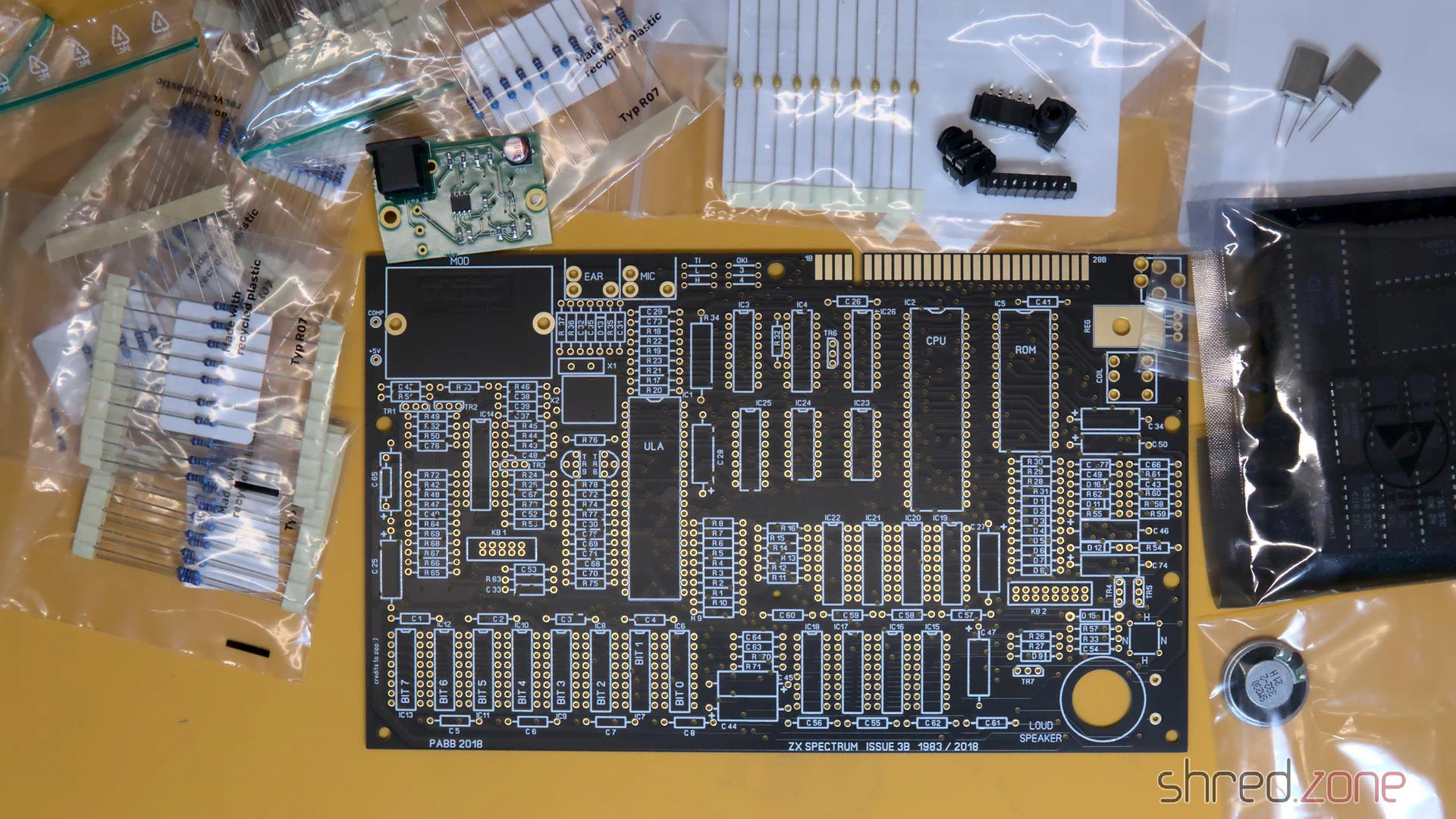
I have put together a bill of materials for the required parts. It contains as many still available components as I could find. The rest can still be obtained as NOS parts from online marketplaces, in some cases there are also replacement types or recreations (like the Retroleum Nebula or vRetro vLA82).
Four wire jumpers determine the type of the upper RAM chips and the ROM chip manufacturer. The correct configuration is also in my bill of materials.
Instead of the modulator, I decided on an S-Video mod and a 3D-printed base plate. A far simpler alternative would be to solder an RCA connector to COMP and GND and use it as a composite output.
After a lot of soldering, the assembly was finally practically finished. But before the valuable chips find their way into their sockets, I checked whether all three voltages (+5V, +12V, -5V) were present and within tolerance.
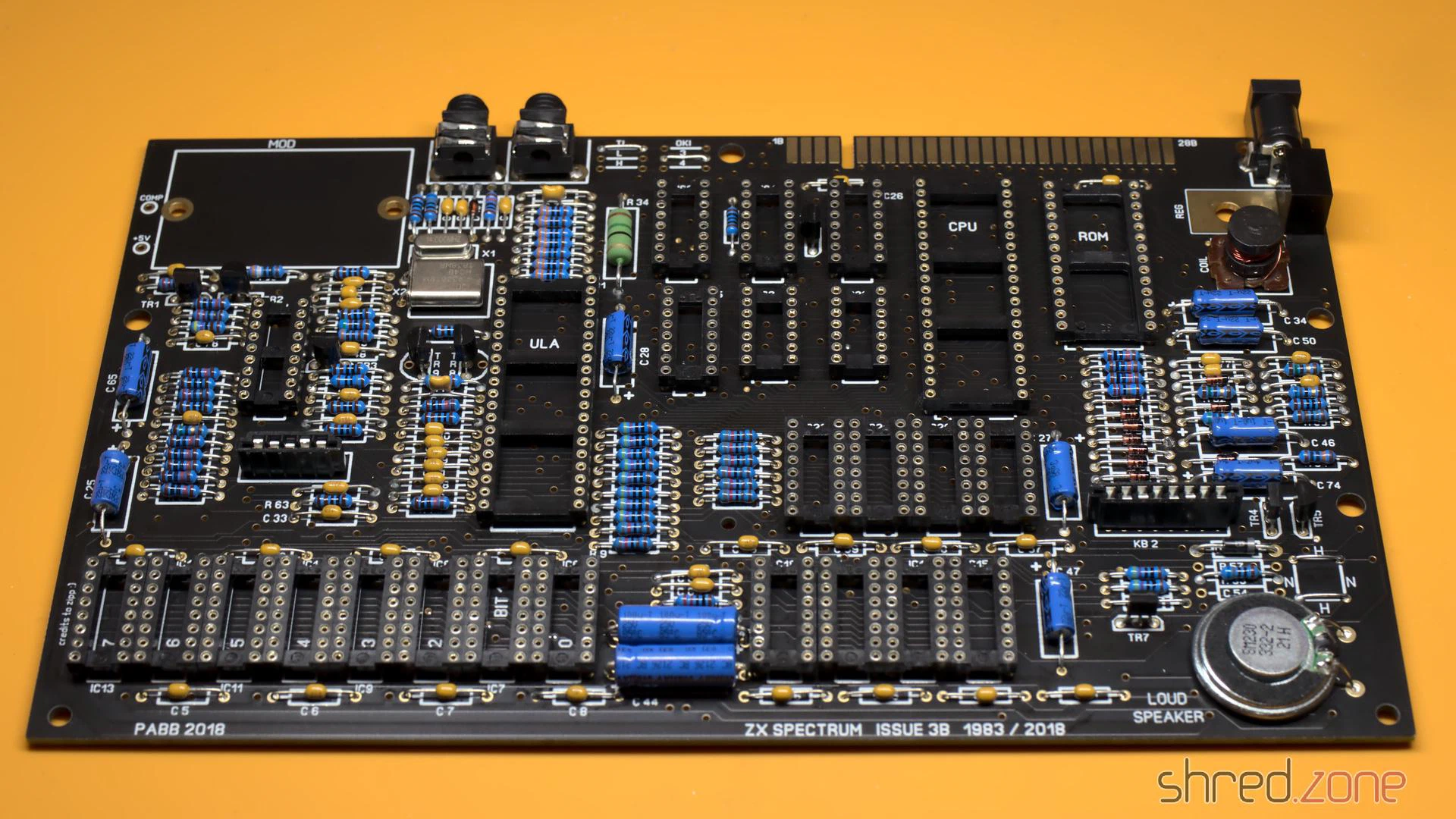
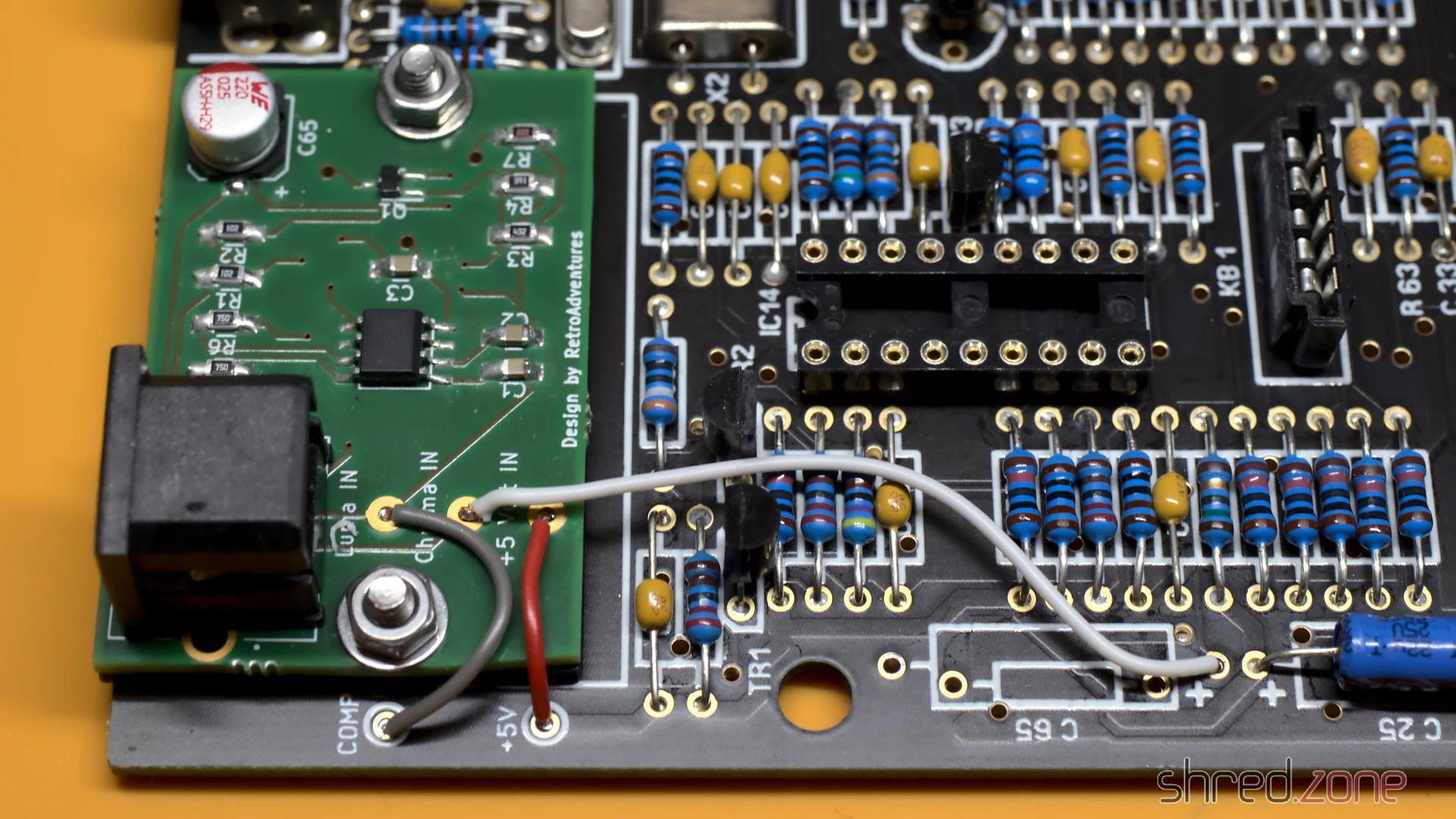
The S-Video mod takes the place of the original modulator, but is not soldered in; instead it is held by two screws. The screws also provide the ground connection, so they must not be made of plastic. Three wires then connect the board to +5V and the composite signal as luma. The chroma signal is connected to the positive end of C65. This must not be populated, so that the luma and chroma signals do not mix.
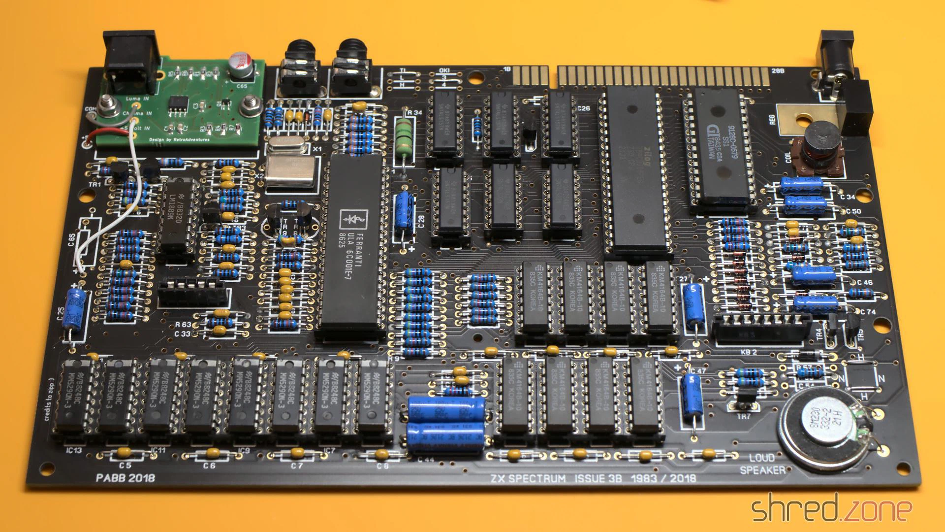
After that, the new board was finally finished and ready for a first test.
Bug fixing
So, power on, and then I saw this:
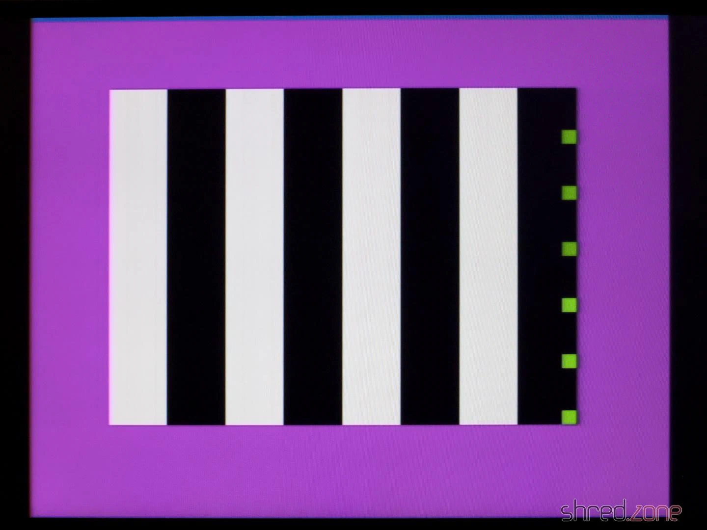
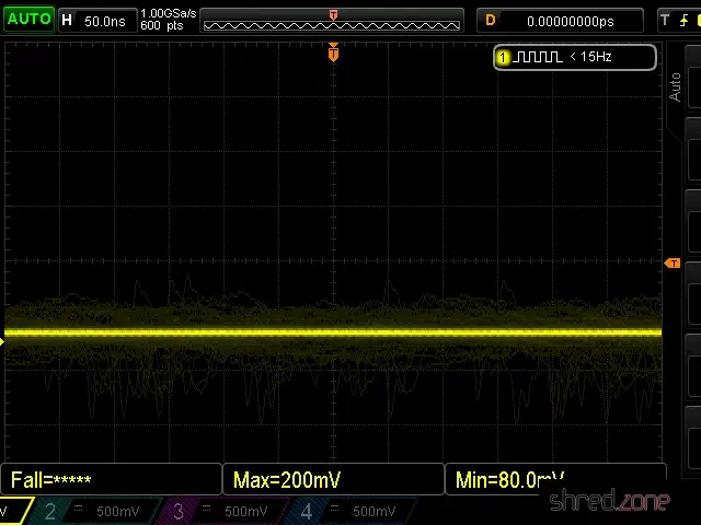
The diagnostic module showed no activity on the CPU bus control lines. My suspicion was confirmed when I checked the CPU clock input with an oscilloscope. Only a flat line could be seen there.
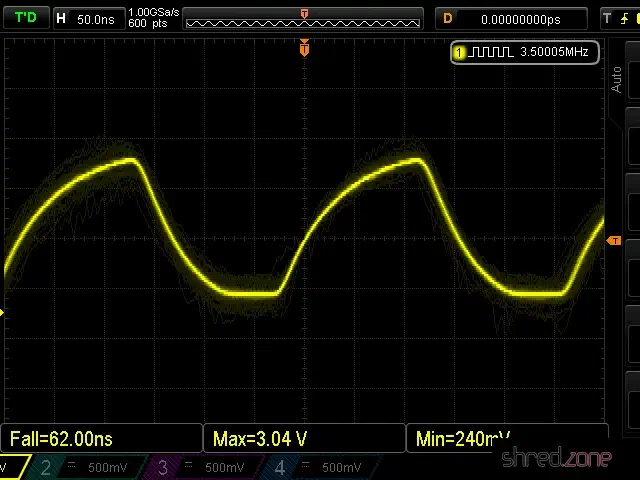
The CPU clock is generated by the ULA, but the clock signal was present there.
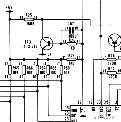
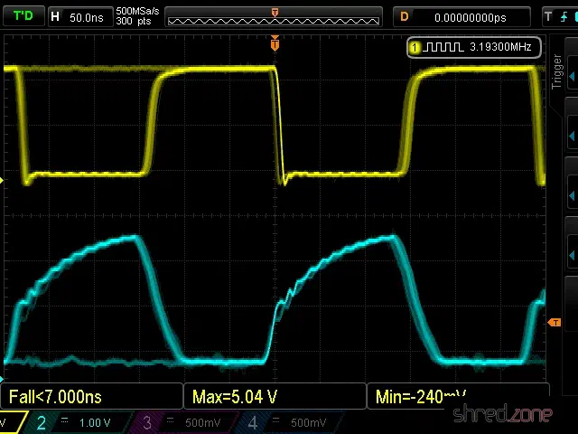
A look at the schematic shows that transistor TR3 is located between the ULA clock output and the CPU clock input, probably to amplify the signal. Strangely, the signal to the right of R24, which is directly connected to the clock output, was still present. However, to the left of R24 (connected there to the base of the transistor), the signal was missing. When I removed TR3, the clock signal appeared there too, so TR3 had to be the cause.
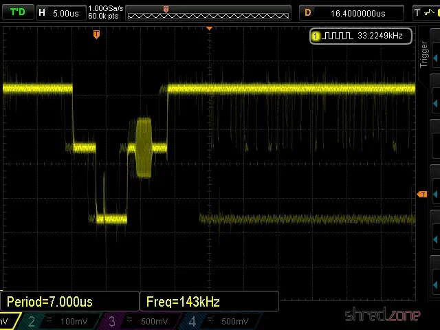
After a longer search, I found out that the Spectrum is very picky about the type used for TR3. The original ZTX313 is no longer manufactured, so I first used a BC548, which was recommended as a replacement type in other places. For TR3, however, the only recommended replacement type is the MPS2369, which is now also hard to come by. With this type, the clock signal was finally fine (cyan: ULA clock output, yellow: CPU clock input).
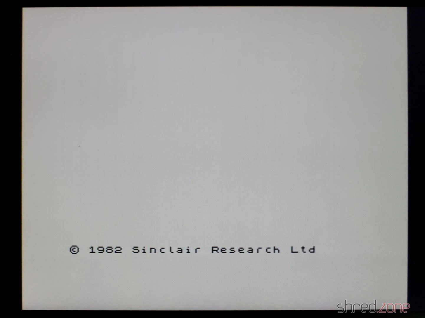
To my delight, the new Spectrum then started up and showed the famous start screen.
As the next step, I carried out a complete diagnosis. Now I got the error that the M1 signal was missing.
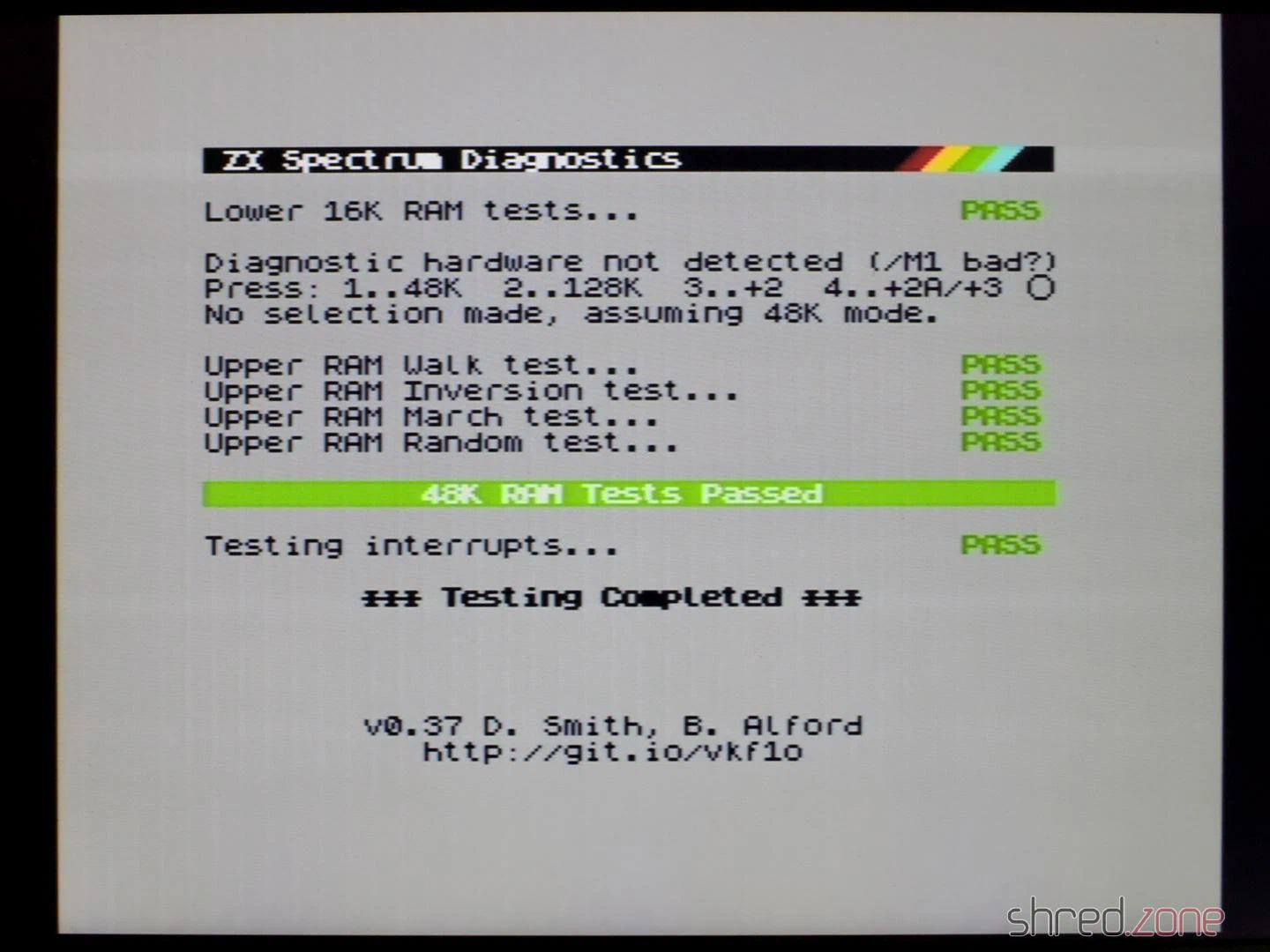
The M1 signal is generated by the CPU and indicates the first of four machine cycles in which the next instruction is read in. The Spectrum itself does not use the M1 signal, but a few expansions like the ZX Interface 1 require it.
After replacing the CPU, all diagnostic checks were finally passed.
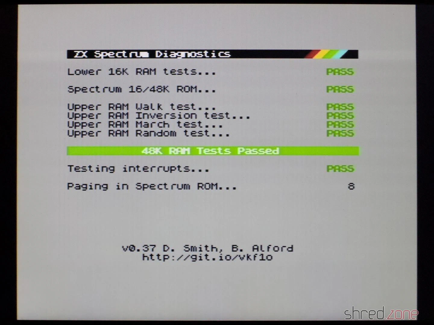
In the end, I could only reuse the ULA, the ROM, the LM1888N and the coil from the old ZX Spectrum. I had also hoped for all the RAM chips and the CPU, but I had less luck with those.
Test run
Anyway, it was finally time for a test run. I connected the new Speccy to my computer and used tzxplay to load my favourite game, Starquake. It loaded and ran perfectly. The picture quality of the S-Video output is also excellent, probably the best you can get out of this old design. Only the ZX Spectrum Next with its digital and pixel-perfect HDMI output has even better quality.
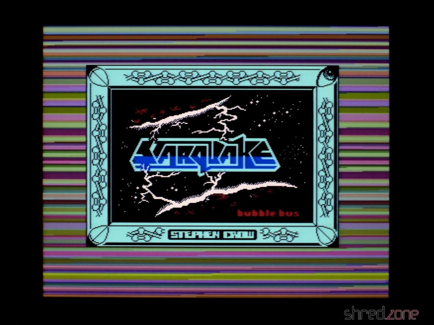
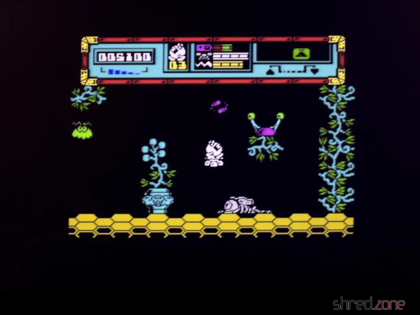
I got the original board without a case. But luckily, there are replica cases, keyboard mats, membranes and faceplates on the market, with which you can assemble a brand new exterior. Of course, I chose a transparent case so that you can admire the beautiful black motherboard from the outside. Well, at least a little bit.
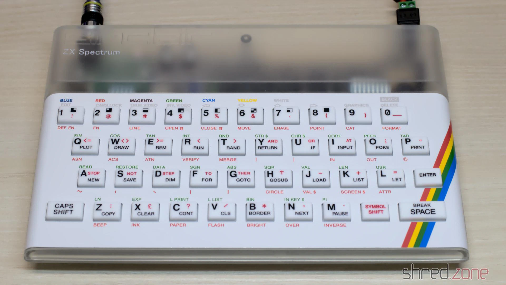
And here it is, a ZX Spectrum in practically new condition.