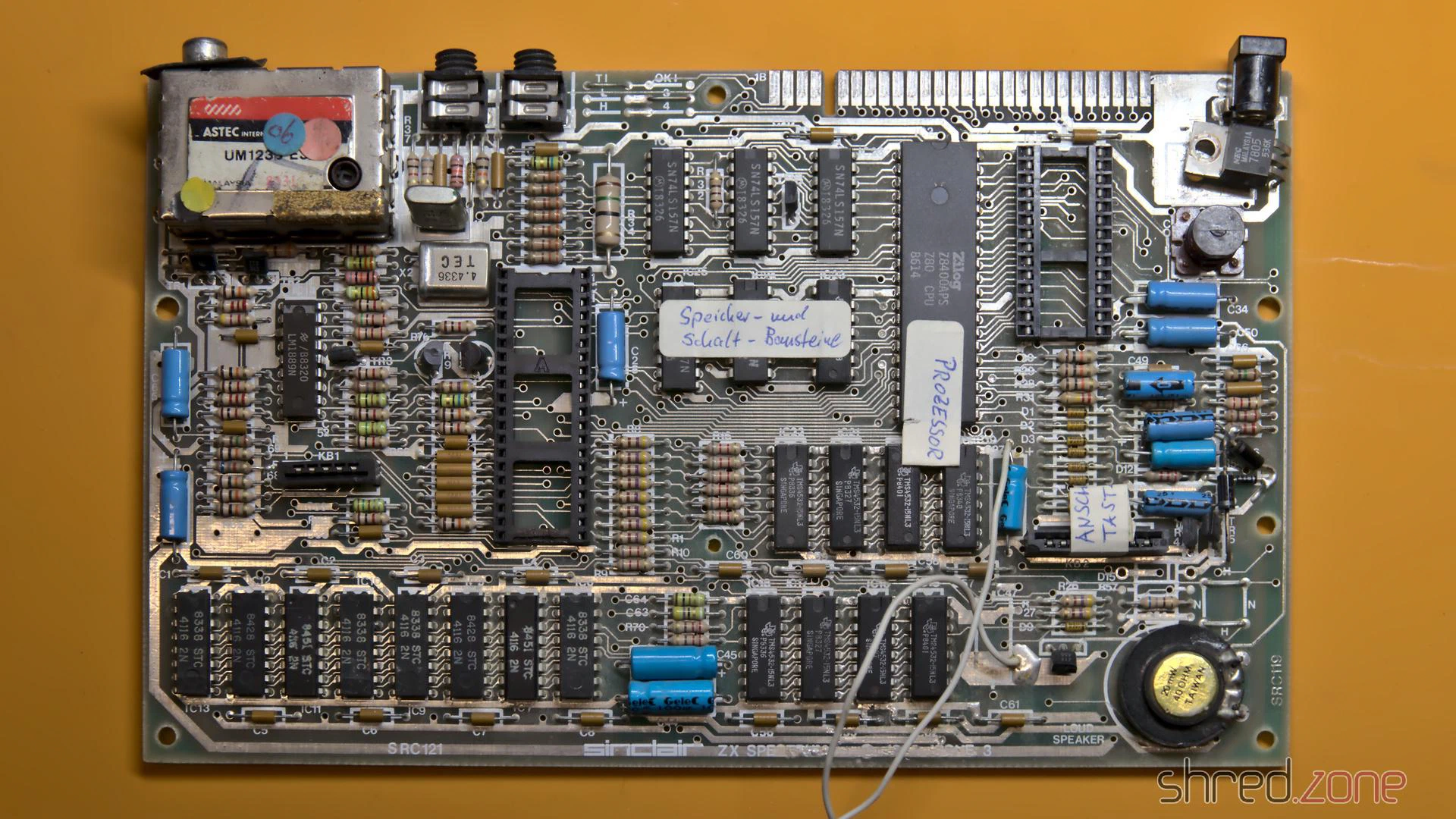
For testing, I plugged in the diagnostic module, but the computer didn’t even start with it and the D0 LED stayed permanently dark. There had to be a short circuit somewhere on the data bus.
That wasn’t too bad, because I plan to build a completely new ZX Spectrum for myself anyway. I want to use as many new components as possible. Only the ULA, the CPU, the LM1889N, the coil and the RAM chips will be reused, as they are no longer manufactured and are correspondingly precious.
So I first removed everything valuable. The scavenged original board was quite a sad sight, but the prospect of a brand new Speccy emerging from it made it less painful.
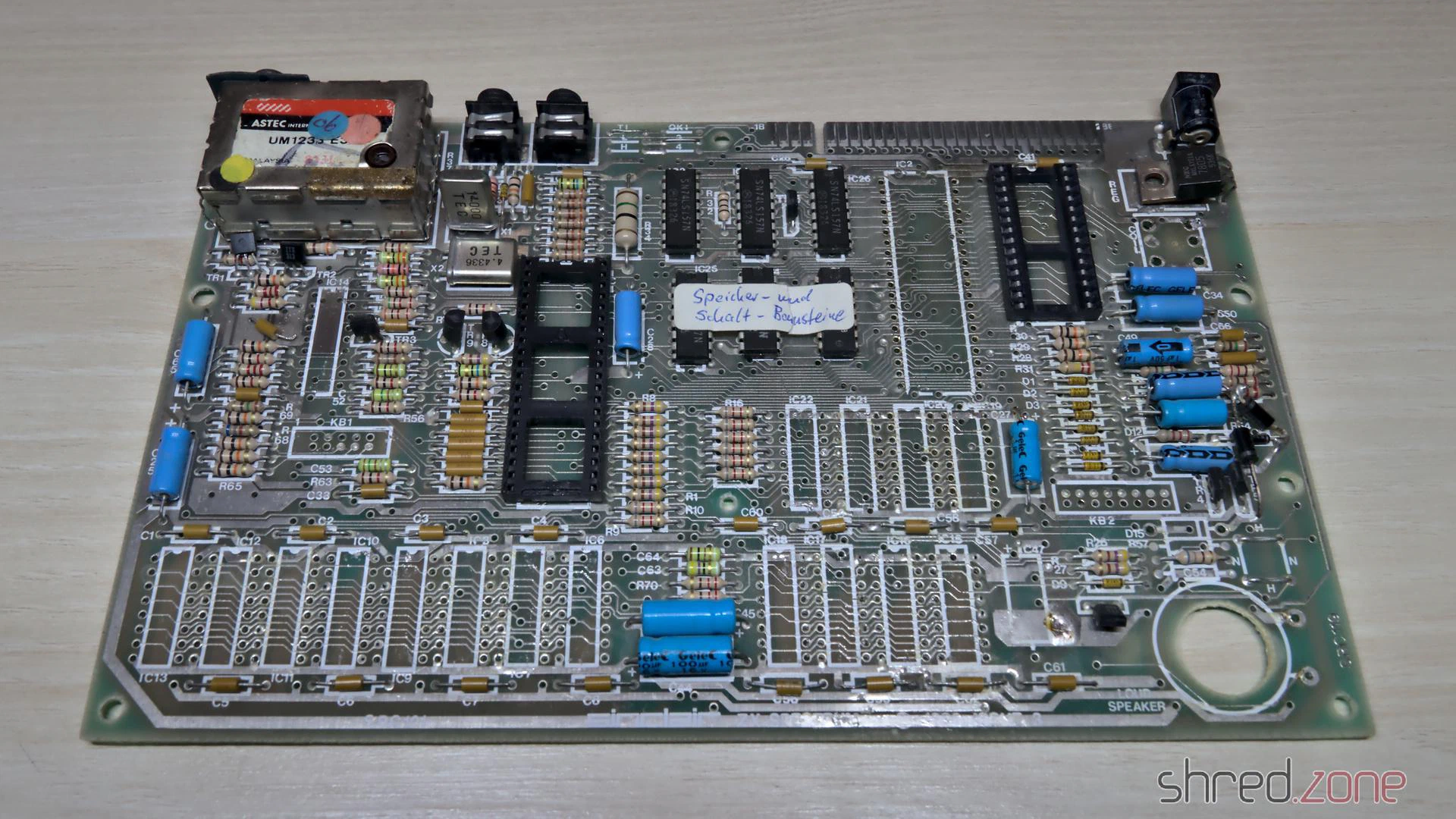
I already checked the ULA in another Speccy, it was fine. Unfortunately, out of the 16 RAM chips, only nine passed the tester. That was much less than I had hoped. I still have a few of these old RAM chips in stock, but replacements are hard to come by.
A new board
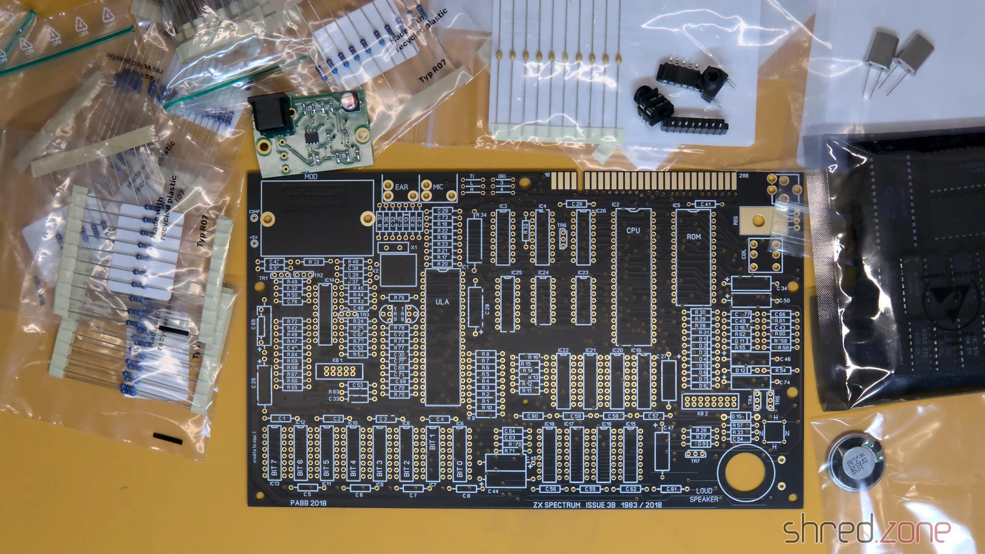
I have put together a bill of materials for the required parts. It contains as many still available components as I could find. The rest can still be obtained as NOS parts from online marketplaces, in some cases there are also replacement types or recreations (like the Retroleum Nebula or vRetro vLA82).
Four wire jumpers determine the type of the upper RAM chips and the ROM chip manufacturer. The correct configuration is also in my bill of materials.
Instead of the modulator, I decided on an S-Video mod and a 3D-printed base plate. A far simpler alternative would be to solder an RCA connector to COMP and GND and use it as a composite output.
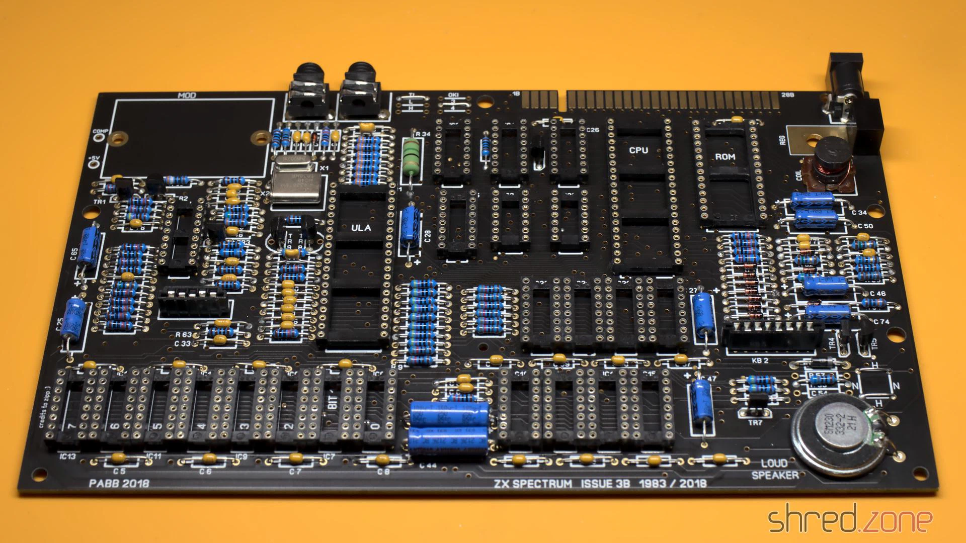
After a lot of soldering, the assembly was finally practically finished. But before the valuable chips find their way into their sockets, I checked whether all three voltages (+5V, +12V, -5V) were present and within tolerance.
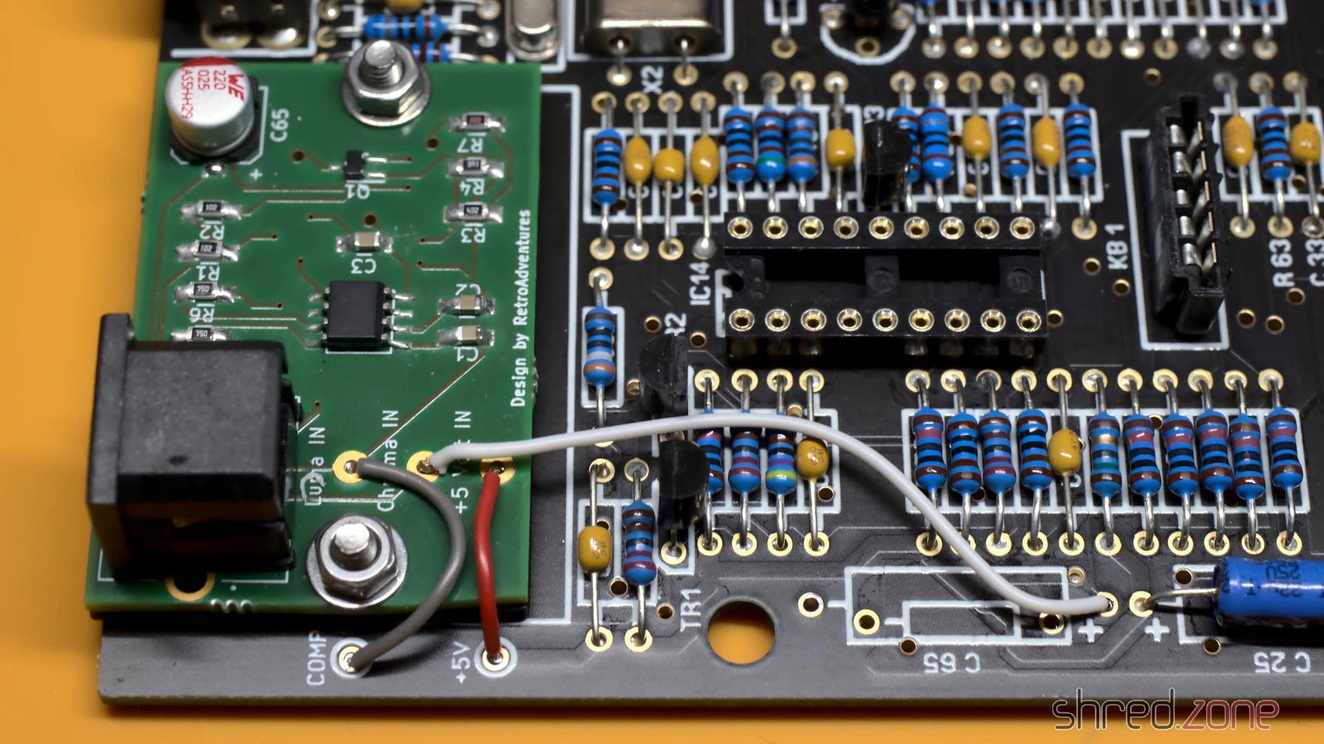
The S-Video mod takes the place of the original modulator, but is not soldered in; instead it is held by two screws. The screws also provide the ground connection, so they must not be made of plastic. Three wires then connect the board to +5V and the composite signal as luma. The chroma signal is connected to the positive end of C65. This must not be populated, so that the luma and chroma signals do not mix.
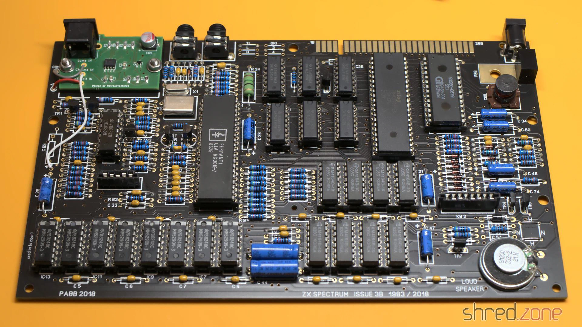
After that, the new board was finally finished and ready for a first test.
Bug fixing
So, power on, and then I saw this:
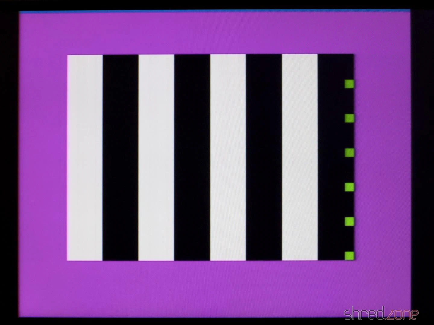
The diagnostic module showed no activity on the CPU bus control lines. My suspicion was confirmed when I checked the CPU clock input with an oscilloscope. Only a flat line could be seen there.
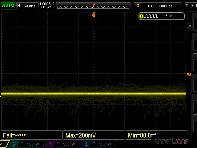
The CPU clock is generated by the ULA, but the clock signal was present there.
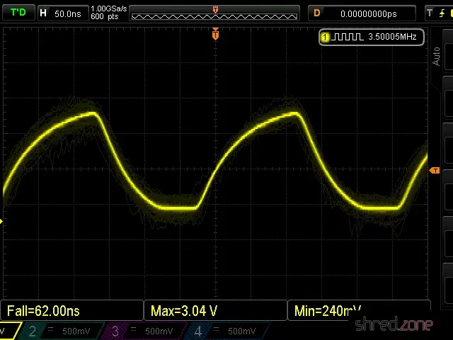
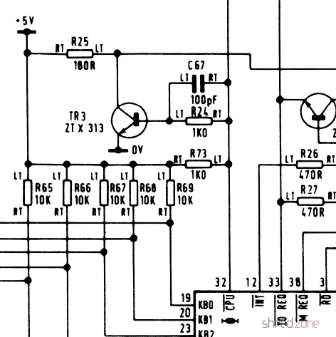
A look at the schematic shows that transistor TR3 is located between the ULA clock output and the CPU clock input, probably to amplify the signal. Strangely, the signal to the right of R24, which is directly connected to the clock output, was still present. However, to the left of R24 (connected there to the base of the transistor), the signal was missing. When I removed TR3, the clock signal appeared there too, so TR3 had to be the cause.
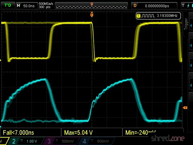
After a longer search, I found out that the Spectrum is very picky about the type used for TR3. The original ZTX313 is no longer manufactured, so I first used a BC548, which was recommended as a replacement type in other places. For TR3, however, the only recommended replacement type is the MPS2369, which is now also hard to come by. With this type, the clock signal was finally fine (cyan: ULA clock output, yellow: CPU clock input).
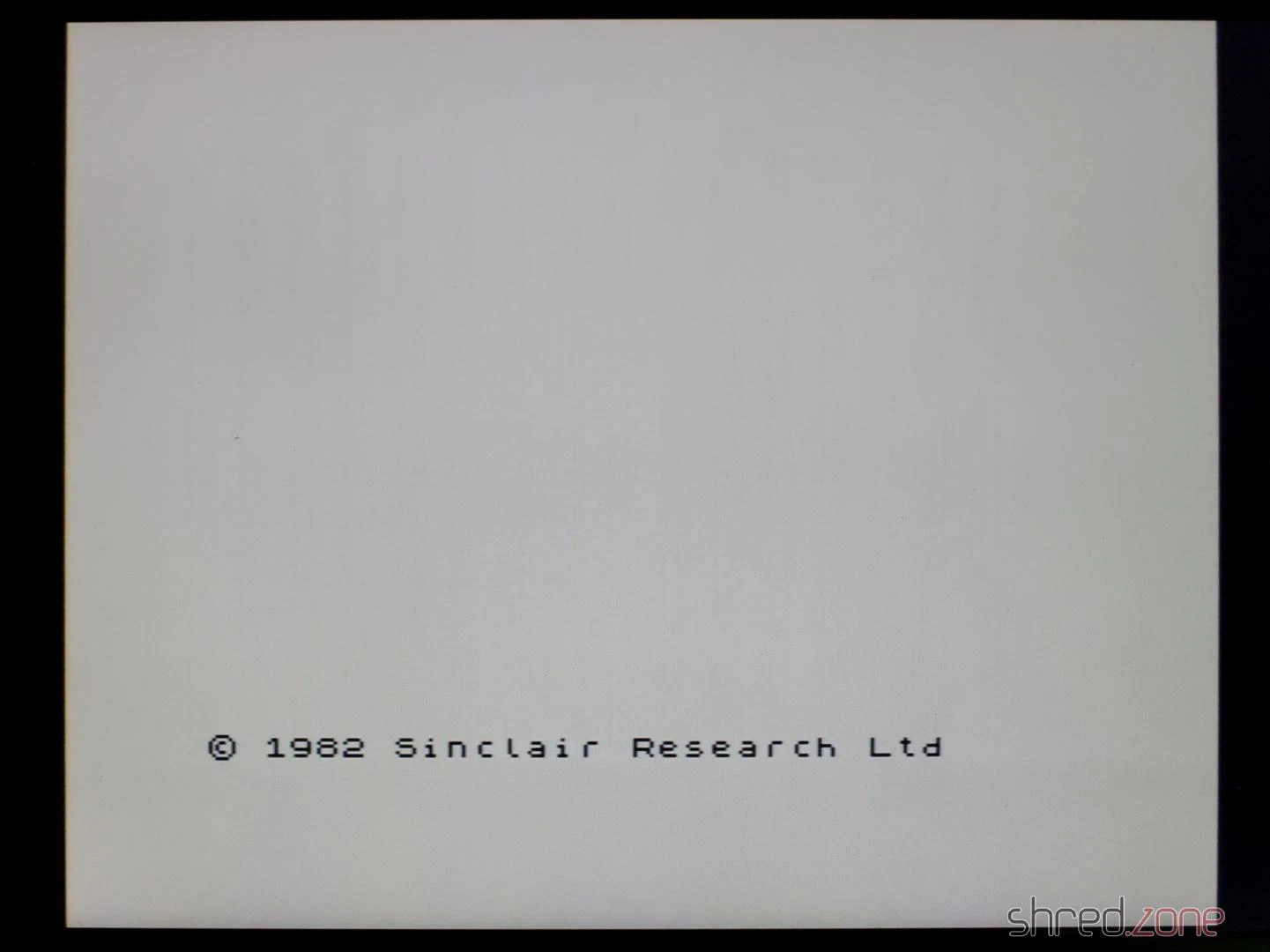
To my delight, the new Spectrum then started up and showed the famous start screen.
As the next step, I carried out a complete diagnosis. Now I got the error that the M1 signal was missing.
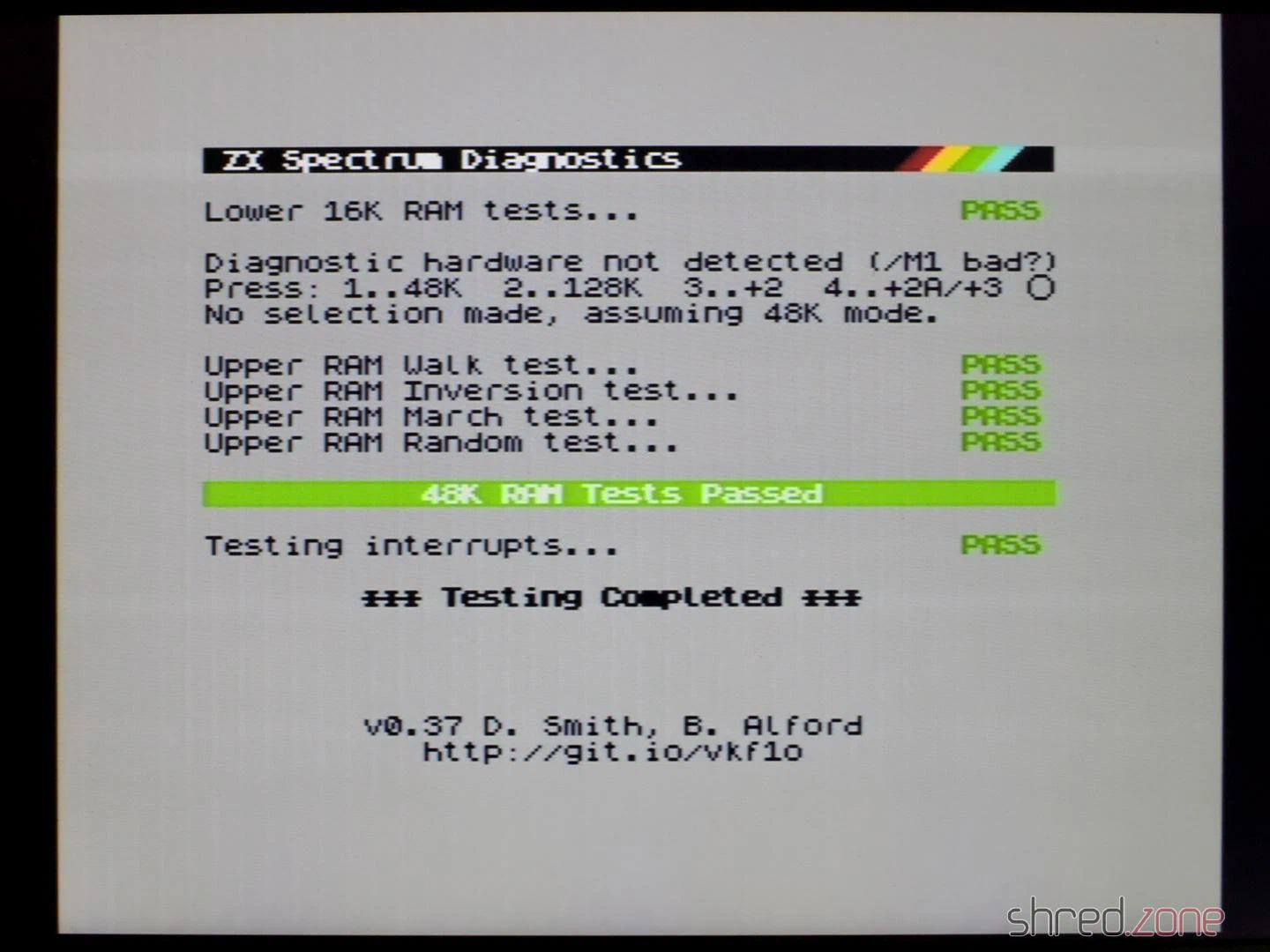
The M1 signal is generated by the CPU and indicates the first of four machine cycles in which the next instruction is read in. The Spectrum itself does not use the M1 signal, but a few expansions like the ZX Interface 1 require it.
After replacing the CPU, all diagnostic checks were finally passed.
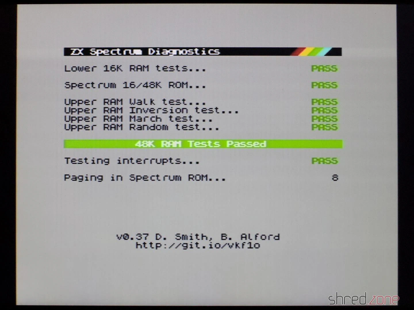
In the end, I could only reuse the ULA, the ROM, the LM1888N and the coil from the old ZX Spectrum. I had also hoped for all the RAM chips and the CPU, but I had less luck with those.
Test run
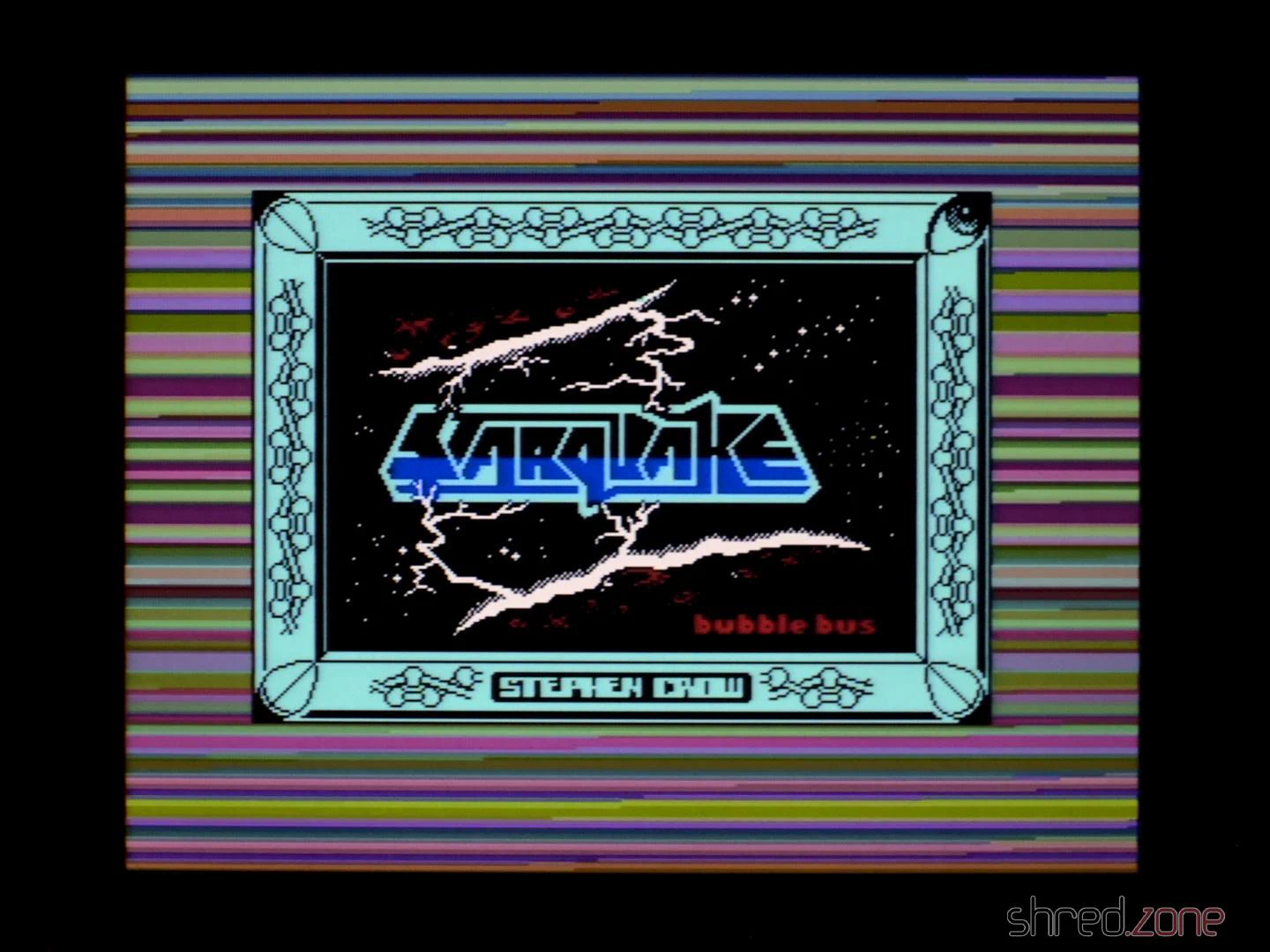
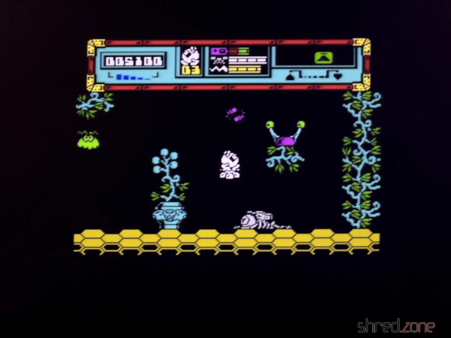
Anyway, it was finally time for a test run. I connected the new Speccy to my computer and used tzxplay to load my favourite game, Starquake. It loaded and ran perfectly. The picture quality of the S-Video output is also excellent, probably the best you can get out of this old design. Only the ZX Spectrum Next with its digital and pixel-perfect HDMI output has even better quality.
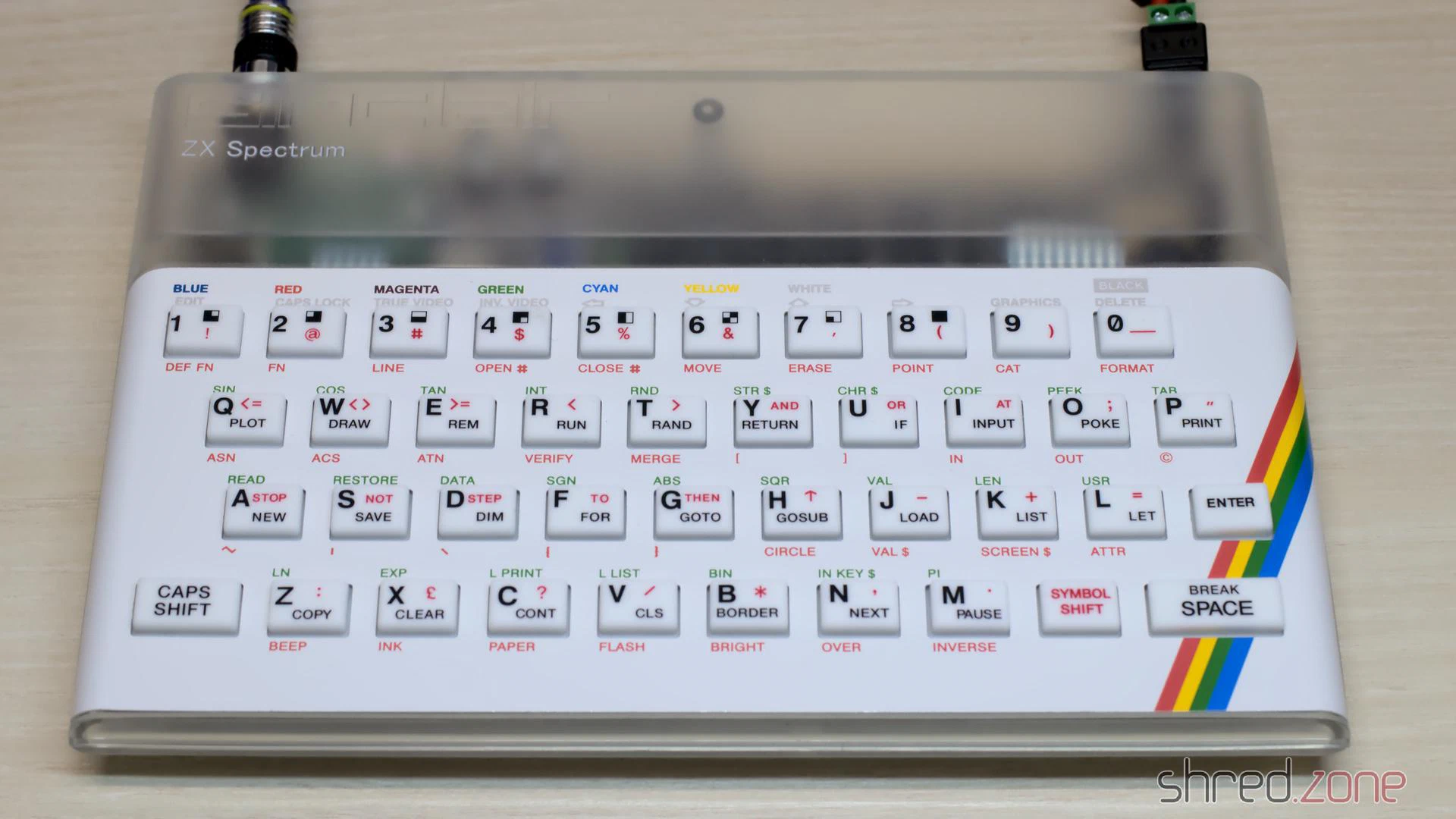
I got the original board without a case. But luckily, there are replica cases, keyboard mats, membranes and faceplates on the market, with which you can assemble a brand new exterior. Of course, I chose a transparent case so that you can admire the beautiful black motherboard from the outside. Well, at least a little bit.
And here it is, a ZX Spectrum in practically new condition.