However, they were quite inconvenient. Cassettes were slow. It took several minutes for a game to load. With a “collection” of several games on one cassette, you first had to fast-forward to the right spot, which wasn’t that easy, as the noise of the data stream sounds pretty much the same to us humans. You could write down the counter readings on the cassette recorder, but the counters weren’t standardised, making the index tied to a specific model.
When I finally got my Amiga with a floppy disk drive, I quickly forgot the times when I had to fiddle with cassettes.
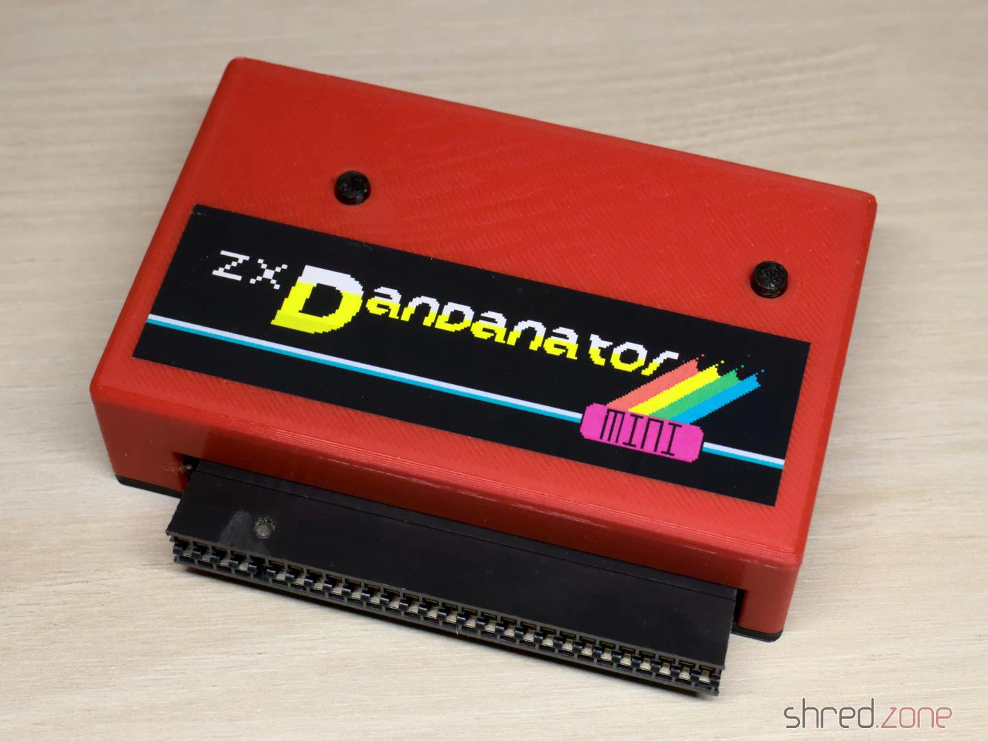
Today I own a few ZX Spectrums, but no cassette recorder anymore. To load software into the computer, I usually use my PC’s headphone jack and tzxplay. But there is a more elegant way. The ZX Dandanator Mini by Dandare is an expansion with 512KB of flash memory where your favourite games can be saved. A boot menu allows you to select one of these games. It is then loaded directly into memory. The Dandanator also offers a Kempston-compatible joystick port.
While assembling my ZX Dandanator Mini, I noticed that the project’s documentation left a few questions unanswered. I hope my blog article will help others with building their own.
Parts
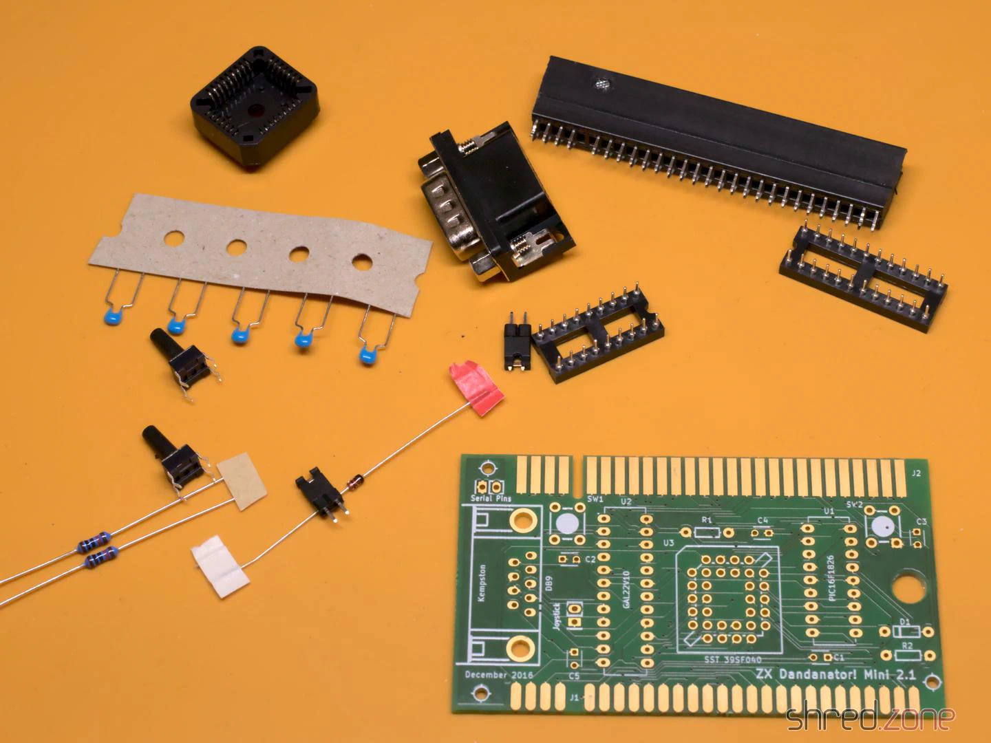
- 1x GAL 22V10 (+ DIP20 socket)
- 1x PIC 16F1826-I/P (+ DIP18 socket)
- 1x SST 39SF040 Flash ROM (+ PLCC32 socket)
- 1x 1N4148 (TH)
- 2x 10kΩ resistors (TH)
- 5x 100nF ceramic capacitors (TH)
- 1x D-Sub connector, 9-pin male, angled, European style (e.g. this one)
- 2x pin headers, 2-pin
- 1x jumper
- 2x tactile switches, 6 mm high (17 mm for the 3D-printed case)
- 1x PCB (Gerber files are here)
- 1x ZX Spectrum Edge Connector (can be found in retro shops, online marketplaces, or DIY)
- 1x 3D-printed case (optional)
You need a programmer capable of flashing the PIC, the GAL, and the Flash ROM (e.g. the XGecu TL-866II Plus with PLCC32 adapter). I also recommend a good PLCC extraction tool.
Classic GALs are no longer produced, but can still be ordered as NOS parts on online marketplaces. A replacement that is still being produced is the Atmel ATF22V10C-10PU. However, you will then additionally need a 3.3kΩ 6-pin resistor network (more on this below).
Assembly
The assembly is straightforward. You start with the flattest components and work your way up to the tallest ones. There are no SMD components, so even a soldering beginner shouldn’t have any problems.
Make sure the sockets are aligned correctly. Unfortunately, there are no markings for pin 1 of the two DIP sockets on the silkscreen. They should be aligned with the notches facing towards the buttons, as seen in the photo. The PLCC socket should match the outline on the silkscreen.
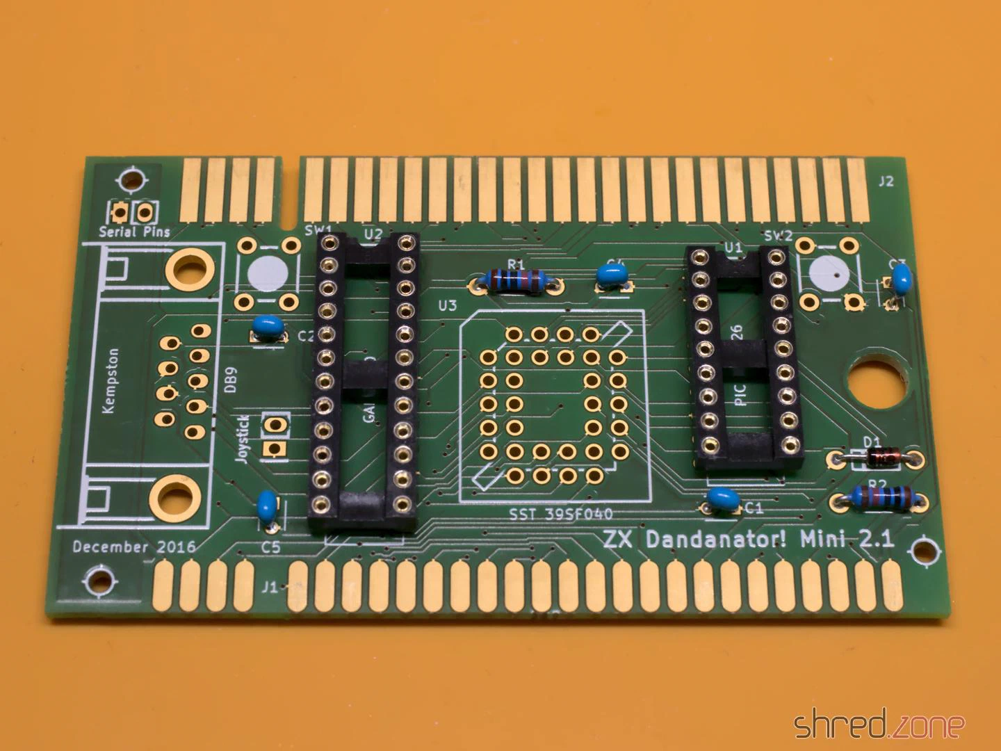
The edge connector is normally meant to be soldered upright, not to the edge of the PCB. So the pins must first be bent inwards on both sides until the connector sits centrally and all pins touch the pads of the PCB. Also, make sure to solder the connector to the correct side of the PCB; that’s the one with the short pads. The connector on the other side is intended for further expansions, such as a joystick interface, but you could even stack several Dandanators together.
If you intend to use the 3D-printed case, leave a gap of about 2 mm between the PCB edge and the connector.
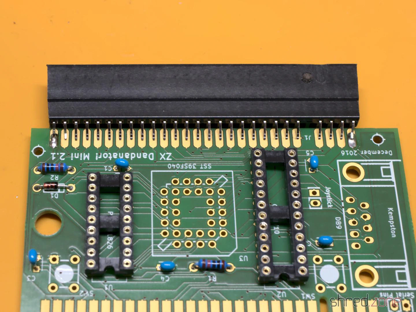
Some of the pads are close to the edge connector on the back. It’s easy to accidentally spill a few drops of solder onto the pads while soldering. A piece of Kapton tape can easily protect them.
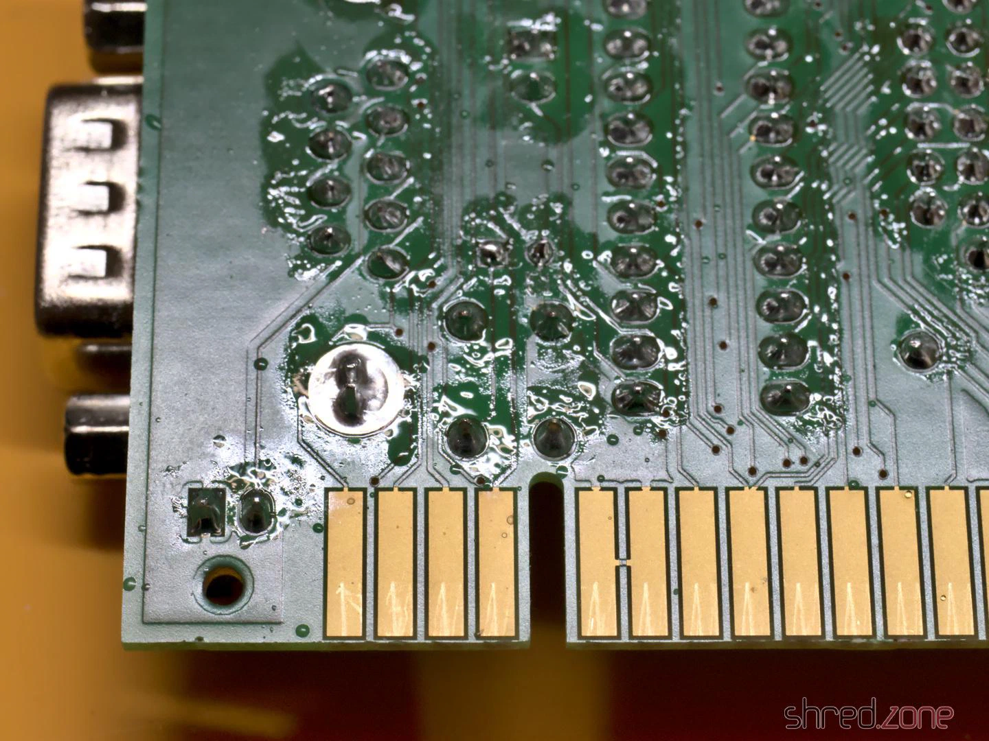
One problem with the ATF22V10C is that it doesn’t have internal pull-ups on the inputs. This means the inputs float when no joystick is connected. This causes problems. On my system, the first game in the list was always started immediately when no joystick was connected. A possible solution is to solder a resistor network onto the bottom side. The resistors are connected to pins 8, 9, 10, 11, and 13 of the ATF22V10C. The common bus is soldered to pin 24. Be careful not to bridge or short-circuit adjacent pins.
This problem shouldn’t occur with the ATF22V10B, but at the time of writing, this variant was either sold out or absurdly expensive.
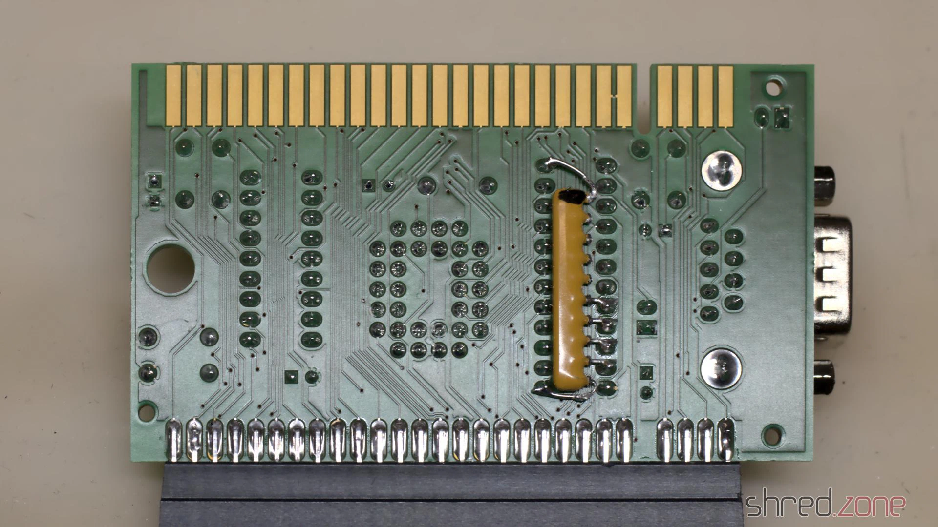
Although this problem probably doesn’t occur with older GALs, the manufacturers still recommend not leaving input pins floating. In my opinion, the pull-up resistors should have been part of the Dandanator design.
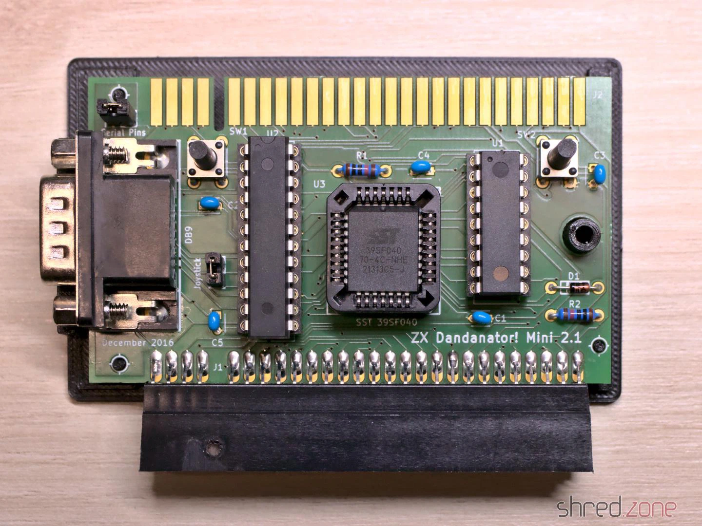
In the final step, you clean the PCB and check it for solder bridges and other faults. A short circuit can destroy the voltage regulator in the ZX Spectrum, which is relatively difficult to repair.
The “Joystick” jumper is there to activate the joystick port. It should be closed if no other joystick interface is used. The “Serial Pins” jumper seems to be intended for in-circuit programming and should not be closed. (Nothing will break if you accidentally close it, but then the joystick will be permanently pressed to the right.)
Once the assembly is complete, the next step is to program the chips. They are all programmed differently.
Flashing the chips
- GAL: The fusemap can be downloaded here. If you are using an ATF22V10 and the XGecu programmer, make sure you select the
(UES)variant as the chip type. - PIC: An initial firmware can be downloaded here. I tried flashing it with the minipro software, but couldn’t get a working PIC this way. Ultimately, I used the original software from XGecu.
- Flash ROM: The Flash ROM contains the games and also pokes. The image file is generated by a ROM Assembler tool.
The ROM Assembler is written in Java, so it runs on every modern operating system. If you know your way around Java, you can easily compile the latest version yourself from the source code. You can also download a jar file from the Dandanator download page and run it using the command java -jar dandanator-mini-*.jar.
The GUI of the ROM Assembler is fairly self-explanatory. You can simply drag and drop TAP, SNA, Z80, and POK files of your favourite games into it until the flash memory is full. In the settings, you can change the font and language, and even use a custom background image.
Many games can be found at World of Spectrum. An extensive collection of POK files is available here.
Once you have put together your favourite games, create a ROM image and write it to the Flash ROM.
Let’s play!
The Dandanator is connected to the ZX Spectrum’s expansion port. Remember to unplug the computer from the power first.
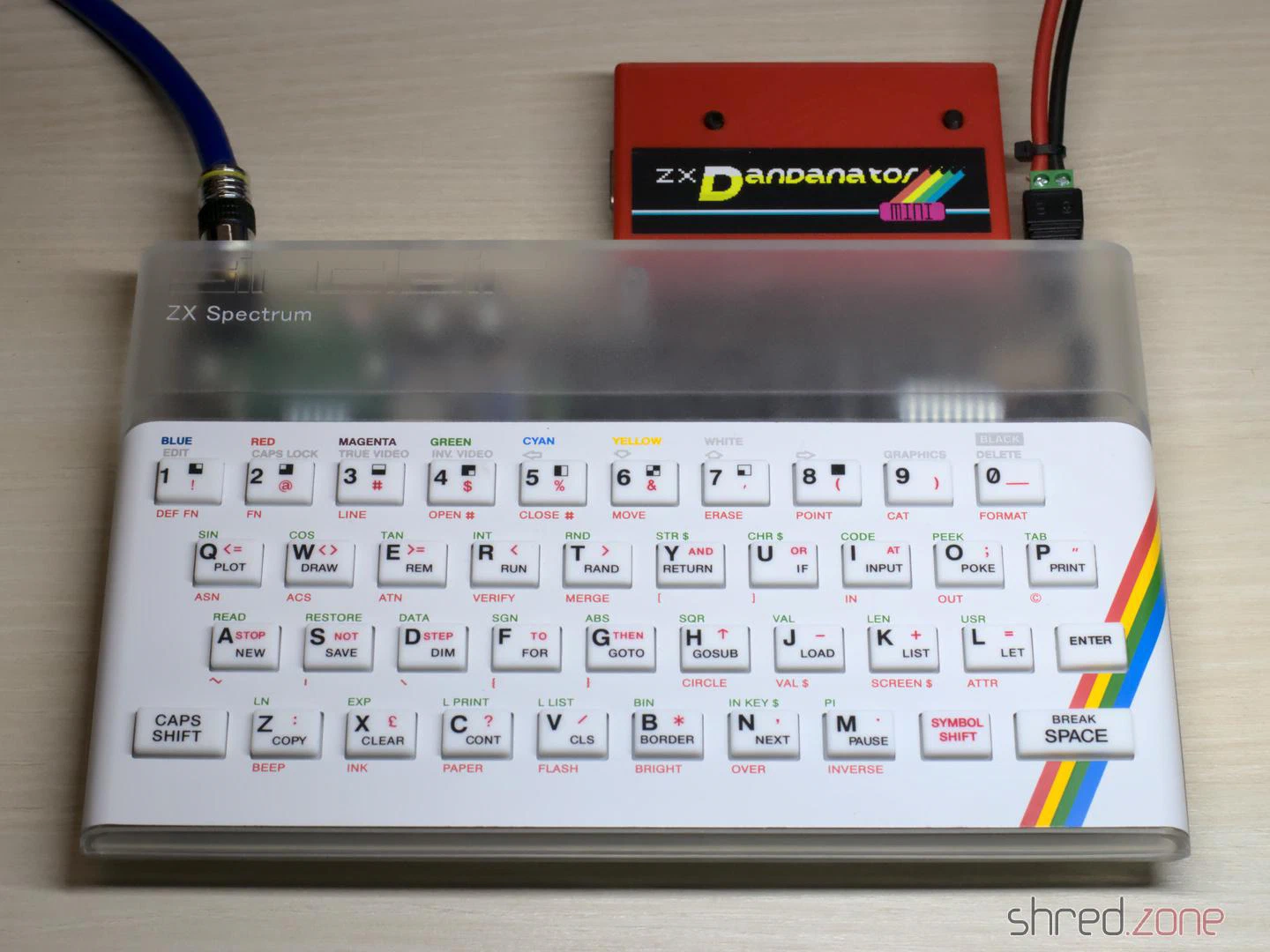
Now switch on your Speccy and press the right button on the Dandanator to reach the main menu.
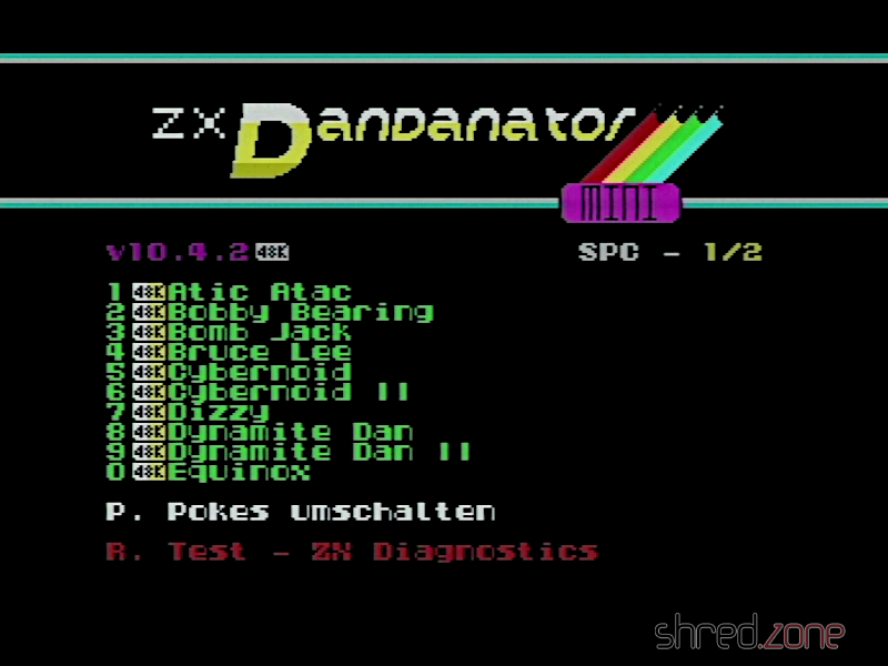
You can select a game, either by using the joystick or pressing the corresponding key, then select the pokes to apply, and finally start the game.
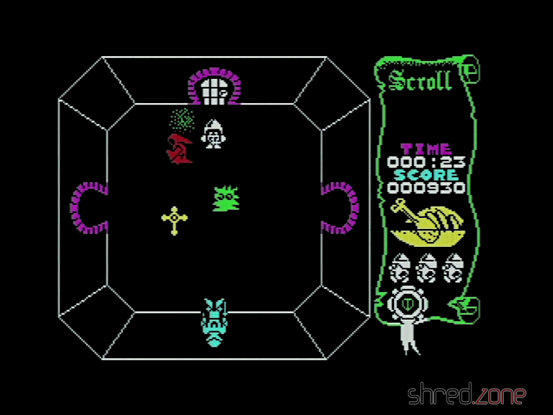
When using the Dandanator for the first time, you should turn the Speccy off, then hold down both buttons and turn it back on. The Dandanator will then flash the latest firmware version to the PIC.
The right button always takes you back to the main menu. The computer no longer needs to be reset.

The project can be found at Codefloe.
The Problem
It all started when my clothes washer broke down. I replaced it with a new one, one that is also IoT capable by using the Home Connect network. I liked the idea because the machine is located in a shared laundry room at the basement of the building. If I knew about the progress and the remaining time, I could go to the basement and swap the laundry right on time, not too soon and not too late.
However, my WLAN does not reach the basement, so I couldn’t connect the washer to the Home Connect cloud. I tried PLC, but that made my DSL connection instable, so it wasn’t a solution either. I pondered about buying an LTE router, but the data tariff would cause monthly costs that I wasn’t really willing to pay.
Then I discovered LoRa, which is a radio communication technique that is specially designed for Long Range (hence its name) communication, with a range of up to several kilometers (on optimal conditions). It should be easy for LoRa to send data from the basement to my flat, and indeed, a first test was successful.
LoRa solves the problem of transporting the data. However, it comes with a price: The individual data packages are very small (about 50 bytes worst case), and in Europe there is also a 1% duty cycle restriction that needs to be respected. So it wasn’t possible to just connect the washer to the Home Connect cloud using LoRa as some kind of WLAN repeater.
Instead of that, I would have to connect to the washer directly, read its state and compress the information to what I actually need, before sending it. The problem is now that the connection between the appliance and the Home Connect cloud is proprietary and encrypted.
I found the solution to that problem in a blog post “hacking your dishwasher” by Trammell Hudson. By smart reverse engineering, Trammell was able to find a way to directly connect to his home appliances, without having to go through the Home Connect cloud. This was the last part of the puzzle that I needed.
Concept
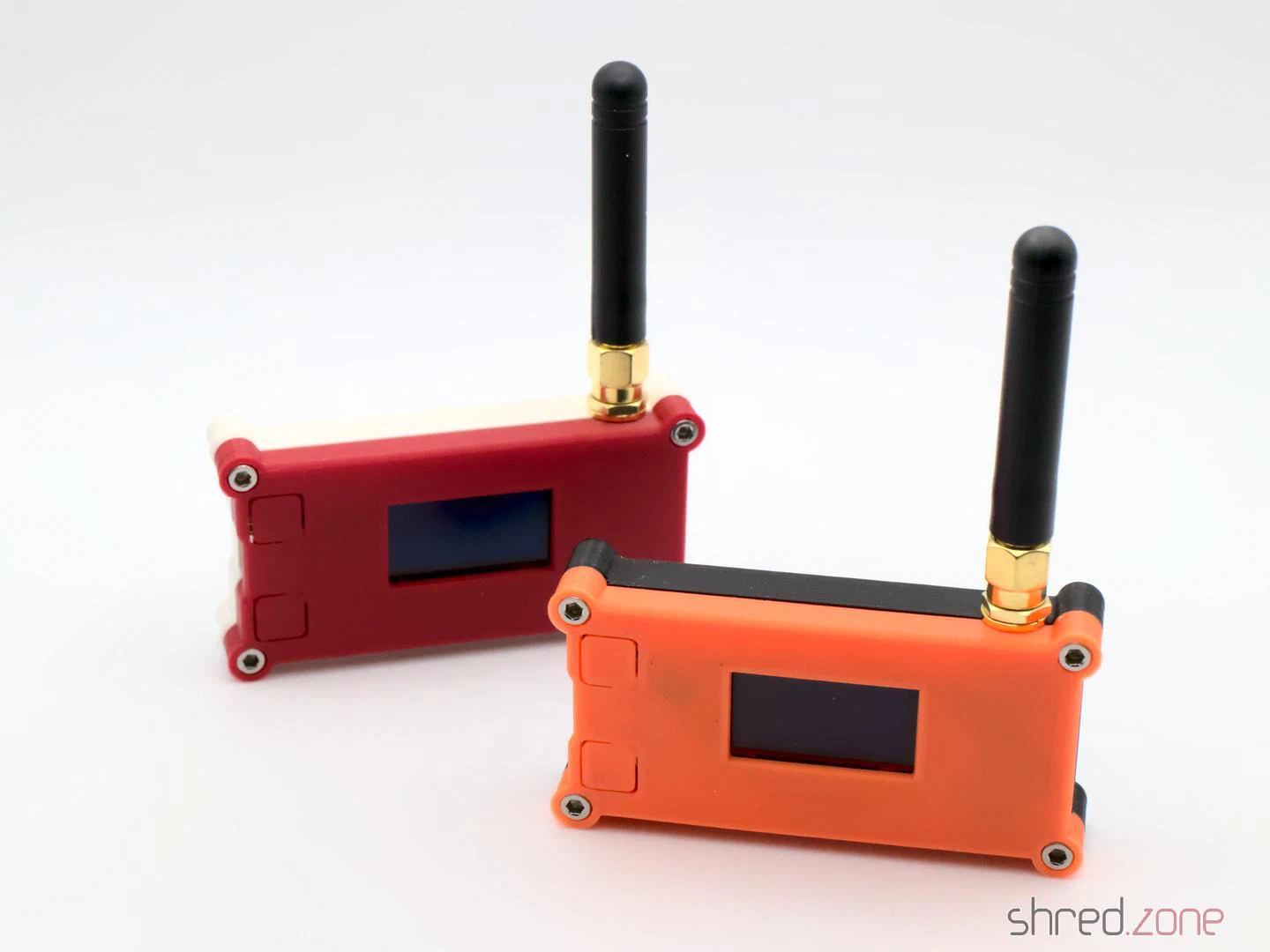
So there is a LoRa “sender” at the basement. It spawns a WLAN access point that the washer connects to. It then communicates with the washer, retrieves its state change events, compresses them, and sends them out via LoRa.
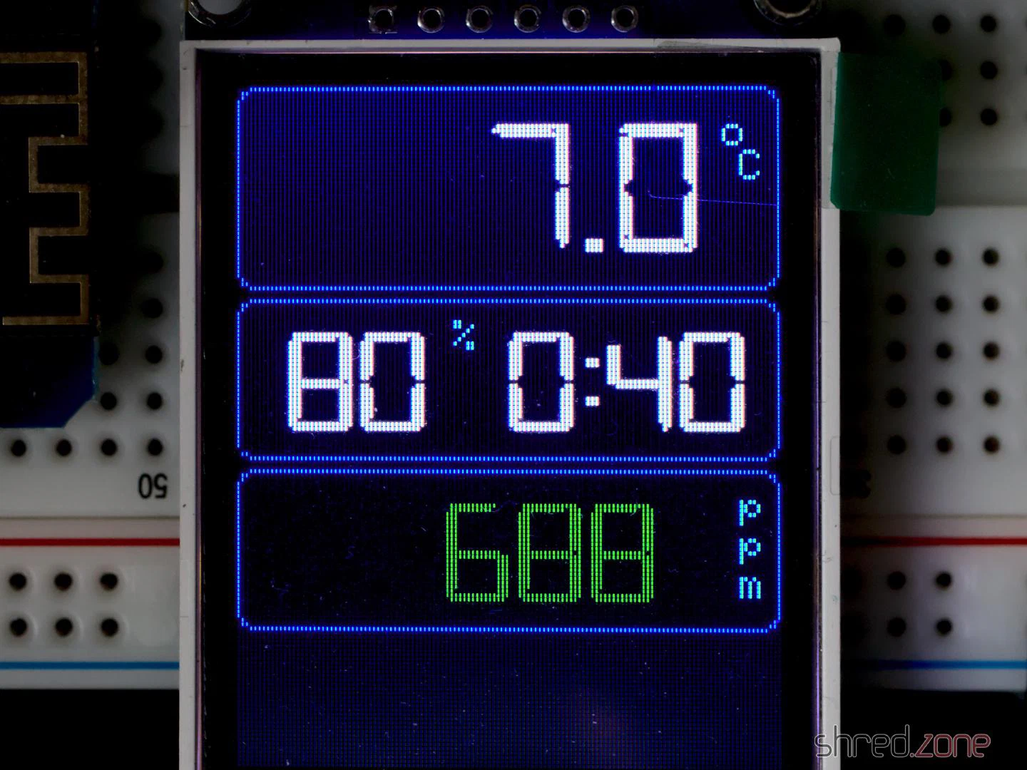
In my flat, a LoRa “receiver” uncompresses the information. From it, JSON bodies are generated and sent to my home automation’s MQTT queue. The generated JSON bodies resemble those sent by Home Connect. A display that is connected to MQTT shows the current progress and the remaining time of the washer. I will also get a message on my phone when the washer is completed, or if an error has occured.
Implementation
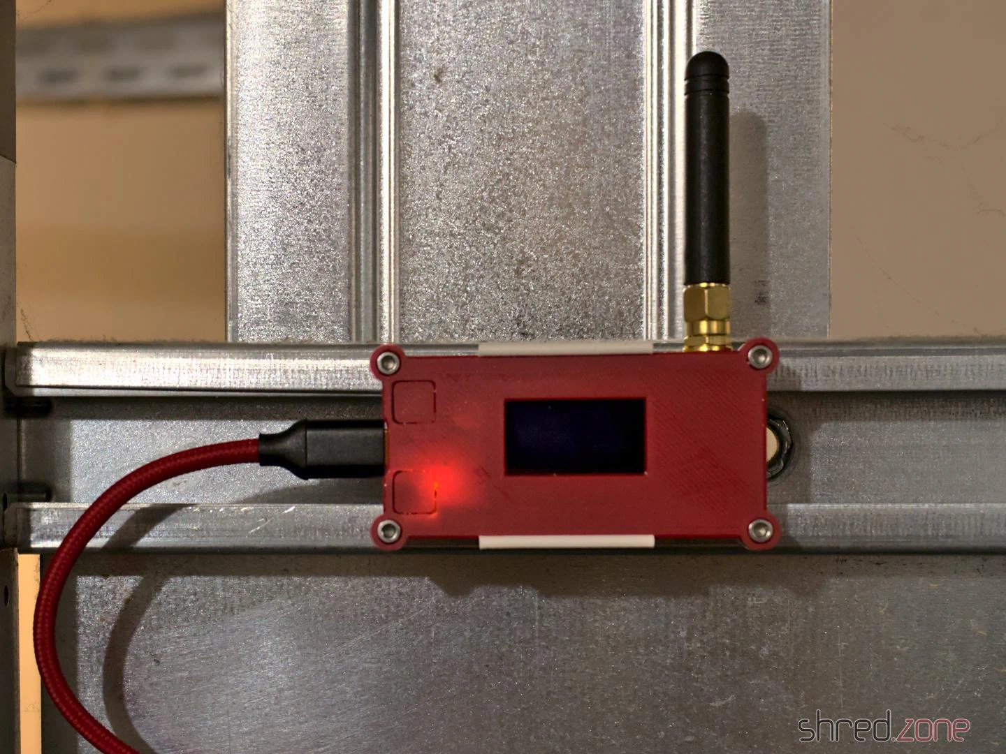
Thanks to Trammell’s hcpy source code, it was surprisingly simple to write a C++ class for the ESP32 that opens a web socket connection to the washer and starts communicating with it.
As mentioned above, the washer is sending JSON messages that contain mostly integer based key-value pairs. To stuff as much information as possible into a single LoRa packet, I came up with a simple compression. The first byte is stating the type of information, followed by a 16-bit integer key, optionally follwed by the value. These are the possible types:
- 0: Represents the constant
0(so no value needs to be transported) - 1: Represents an unsigned 8-bit integer (so the value consumes 1 byte)
- 2: Represents a negative unsigned 8-bit integer (the positive value is transported, and then negated on the receiver side)
- 3,4: The same, but for 16-bit integers (the value consumes 2 bytes)
- 5,6: The same, but for 32-bit integers (the value consumes 4 bytes)
- 7: A boolean constant
false(so no value needs to be transported) - 8: A boolean constant
true(so no value needs to be transported) - 9: A string (followed by the null-terminated string as value)
These key-value pairs are collected until the LoRa package is full or the sender is flushed. A length byte is added that contains the total length of the pairs, so the receiver is able to unpack all of them again.
To secure the communication, a SHA256 based HMAC is generated. A random 16 bit package number is added as well, which is used by the receiver for acknowledgement. Finally, the package is encrypted using AES256.
The receiver side will unencrypt the package and generate an HMAC, using a shared secret. If the HMAC matches, an acknowledge package with the package number is sent back to the sender. After that, the payload is uncompressed and converted to JSON strings that are sent to MQTT.
It is important to know that the transport encryption is not state-of-the-art. There are several sacrifices that had to be made to keep the LoRa transport small and simple:
- Only the first 4 bytes of the MAC are used, for space reasons.
- The RSA256 encryption does not use a mode of operation, mainly because it would be hard to re-synchronize the LoRa connection if a package was lost. On the other hand, we are only sending the washer state. If someone would want to find out whether the washer is running or not, they could just check if a package has been sent within the past minute.
- The transport is not secured against replay attacks. The receiver should provide a random nonce, which is then used by the sender for the next package. This is something that should definitely be addressed.
So the LoRa connection provides an acceptable encryption, and is also protected against lost packages, since the sender will reattempt to send the package if there was no acknowledgement from the receiver.
Configuration
To directly connect to the Home Connect appliance, an encryption key and (depending on the protocol) an initialization vector is required. Both parts cannot be retrieved by the public Home Connect API, but you need to trick the API into thinking that you are connecting from the Home Connect app. This is where Trammell’s hcpy project comes into play. It will let you log into your Home Connect account, and then extract a profile of your appliance and writes it into a config.json file. This file is required for setting up my project.
The config-converter.py in my project will take this config.json file and extract all the necessary parts from it. It will print the appliance’s key and iv values for your sender/config.h. It will also create a new random shared secret for the LoRa encryption. And last but not least, it will create a receiver/mapping.cpp file, which is used to convert the integer keys and values to strings similar to the Home Connect API.
If you came this far, you made the hardest part. After that, the LoRa transceivers need to be configured. Unfortunately the parameters depend on the country where the sender is used, so there are no general default settings.
The following values are proposals and are only valid for countries of the EU. You are responsible to find the correct settings for your country. Failure to do so may result in legal problems, claims for damages, and even imprisonment.
LORA_BAND: This is the frequency used for LoRa transmissions. For EU countries this is usually867E6.LORA_POWER: The power of the LoRa sender, in dB. For EU countries this must be 14 or less.LORA_PABOOST:truefor EU countries.LORA_SPREADING: The spreading factor. For EU countries, values between 7 and 12 are allowed. Higher values span longer distances, but also exhaust the permitted 1% duty cycle sooner. You should use the lowest possible value that gives a stable LoRa connection, and rather try to enhance reception by finding a better place for the LoRa devices or by using better antennas. The value should be 9 or less, as the duty cycle limit is likely to be exceeded with higher spreading factors.LORA_BANDWIDTH: The bandwidth, must be125E3in EU countries.LORA_SYNCWORD: A sync word. You can choose basically any values, or just use the default0x12.
Make sure that the sender and the receiver are using the same settings, otherwise the transmission will fail.
The other settings are mainly about the WLAN access point for your appliance, the WLAN settings of your home network, and the credentials to access your MQTT server.
And that’s it! Actually it was quite a fun project, and I learned a lot about ESP32 programming and LoRa networks. I also spent way too much time with it, but maybe it will pay off because I get the laundry done sooner now.
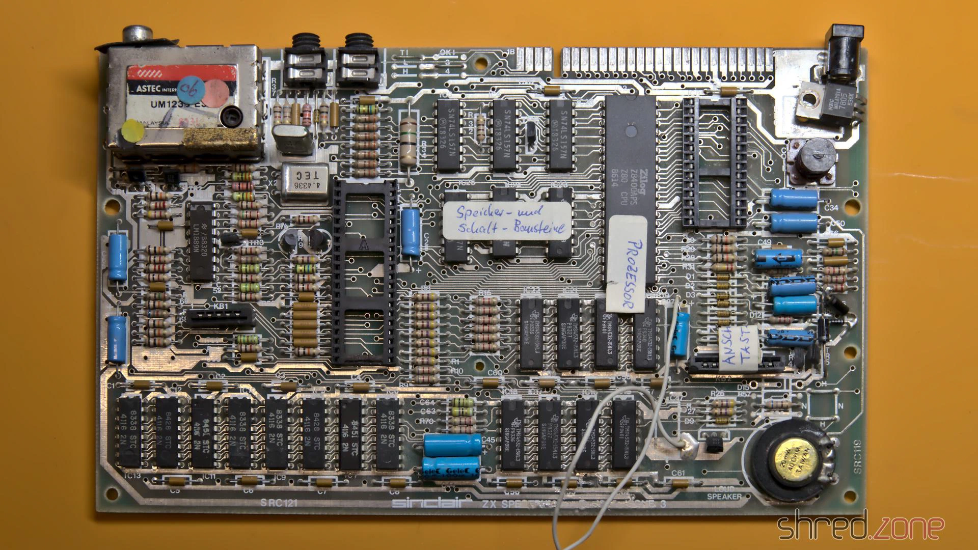
For testing, I plugged in the diagnostic module, but the computer didn’t even start with it and the D0 LED stayed permanently dark. There had to be a short circuit somewhere on the data bus.
That wasn’t too bad, because I plan to build a completely new ZX Spectrum for myself anyway. I want to use as many new components as possible. Only the ULA, the CPU, the LM1889N, the coil and the RAM chips will be reused, as they are no longer manufactured and are correspondingly precious.
So I first removed everything valuable. The scavenged original board was quite a sad sight, but the prospect of a brand new Speccy emerging from it made it less painful.
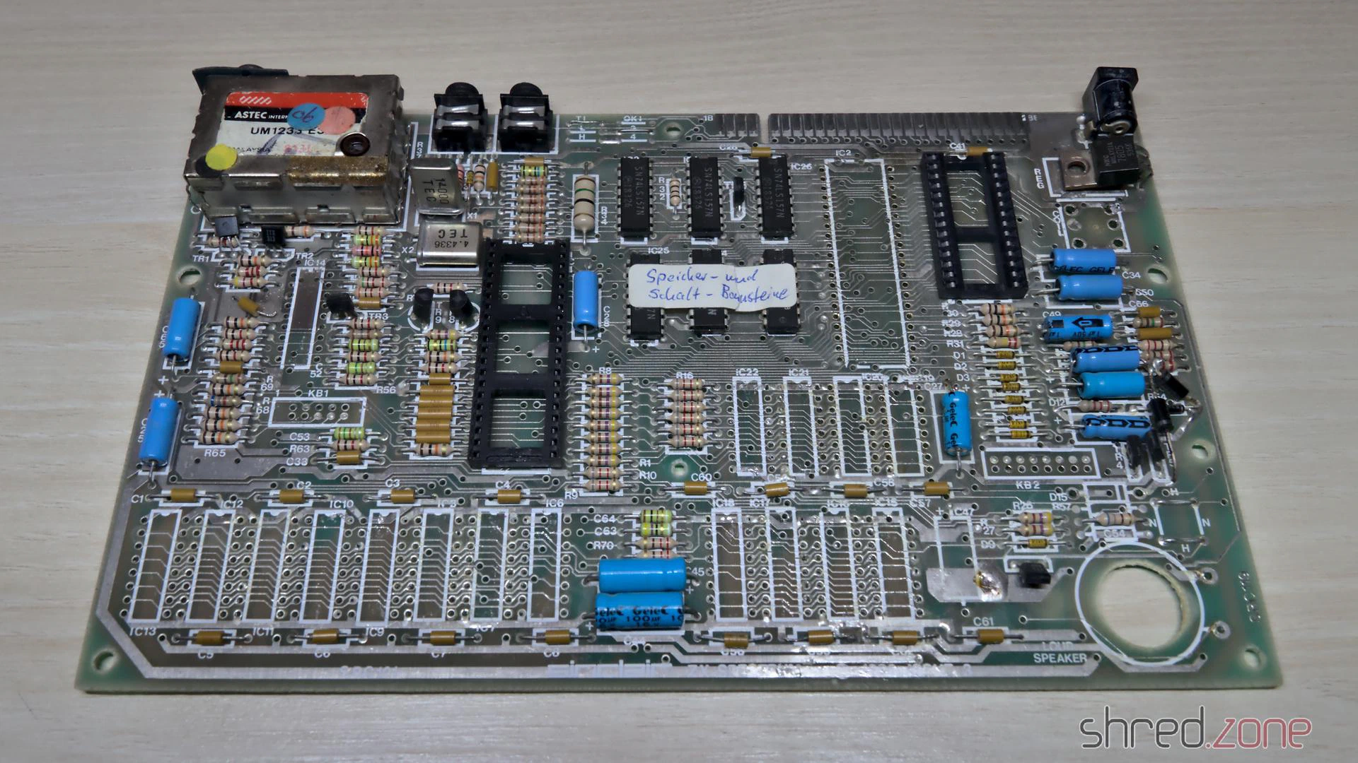
I already checked the ULA in another Speccy, it was fine. Unfortunately, out of the 16 RAM chips, only nine passed the tester. That was much less than I had hoped. I still have a few of these old RAM chips in stock, but replacements are hard to come by.
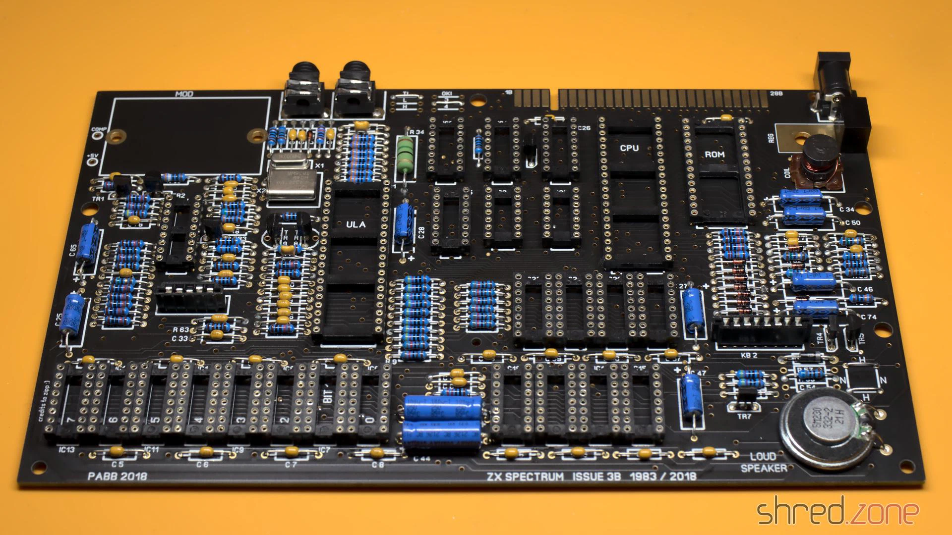
A new board
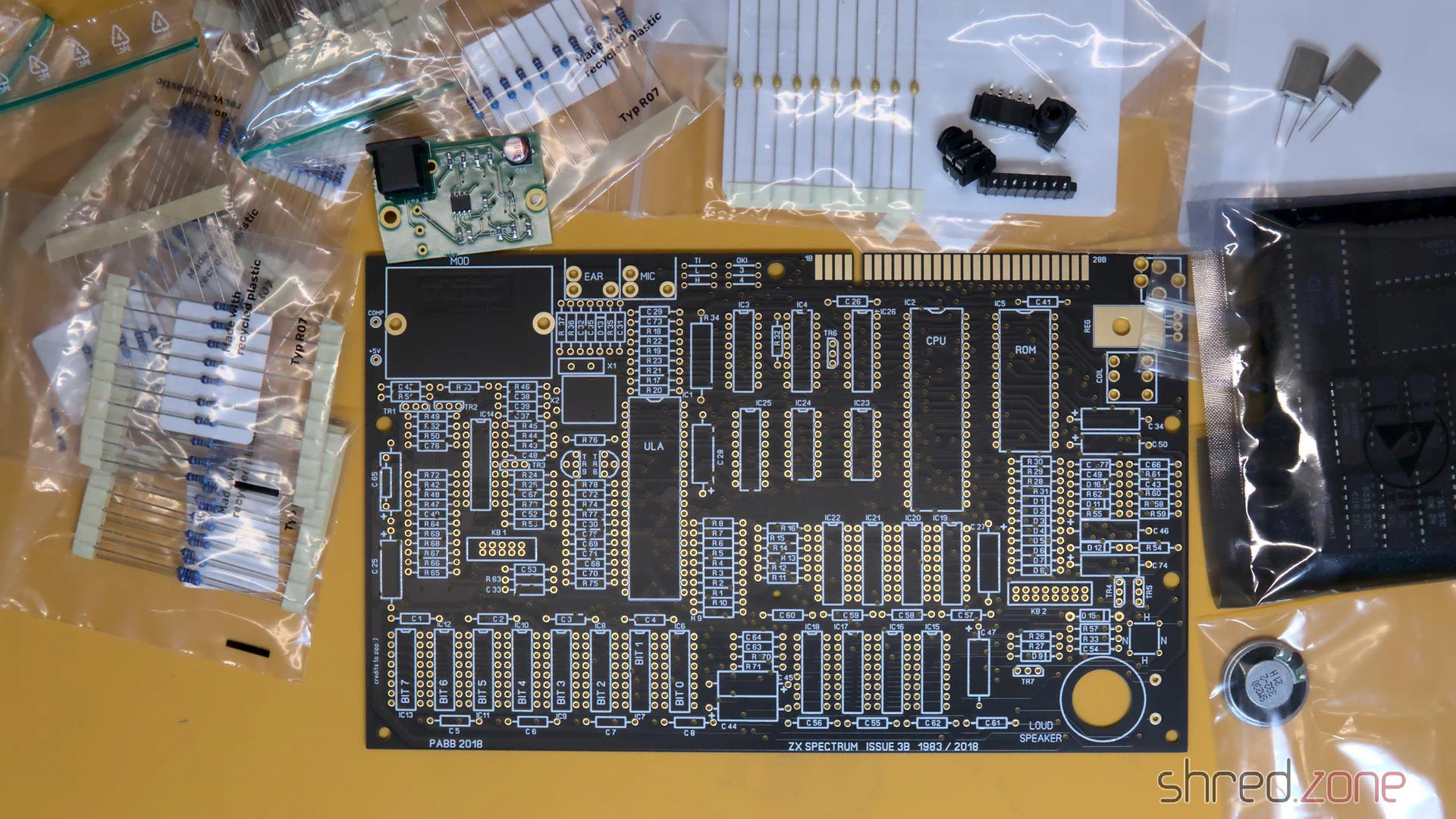
I have put together a bill of materials for the required parts. It contains as many still available components as I could find. The rest can still be obtained as NOS parts from online marketplaces, in some cases there are also replacement types or recreations (like the Retroleum Nebula or vRetro vLA82).
Four wire jumpers determine the type of the upper RAM chips and the ROM chip manufacturer. The correct configuration is also in my bill of materials.
Instead of the modulator, I decided on an S-Video mod and a 3D-printed base plate. A far simpler alternative would be to solder an RCA connector to COMP and GND and use it as a composite output.
After a lot of soldering, the assembly was finally practically finished. But before the valuable chips find their way into their sockets, I checked whether all three voltages (+5V, +12V, -5V) were present and within tolerance.
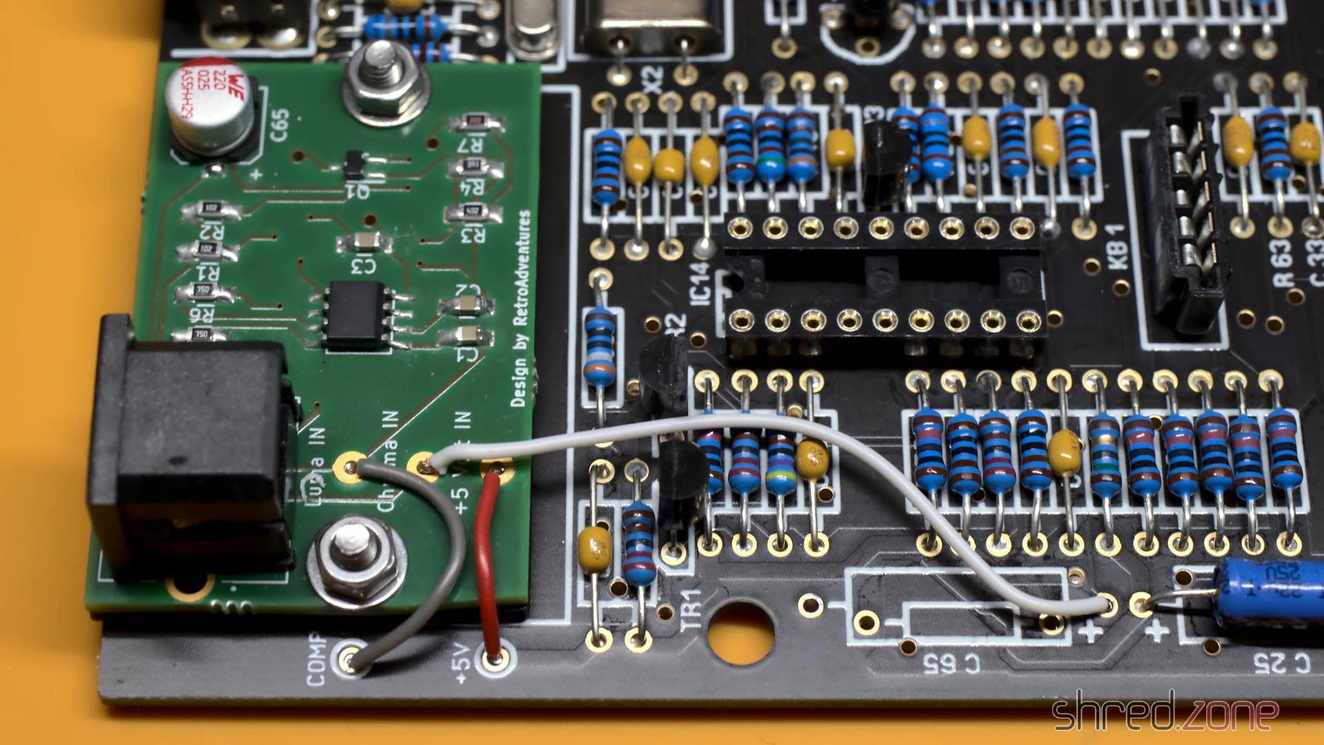
The S-Video mod takes the place of the original modulator, but is not soldered in; instead it is held by two screws. The screws also provide the ground connection, so they must not be made of plastic. Three wires then connect the board to +5V and the composite signal as luma. The chroma signal is connected to the positive end of C65. This must not be populated, so that the luma and chroma signals do not mix.
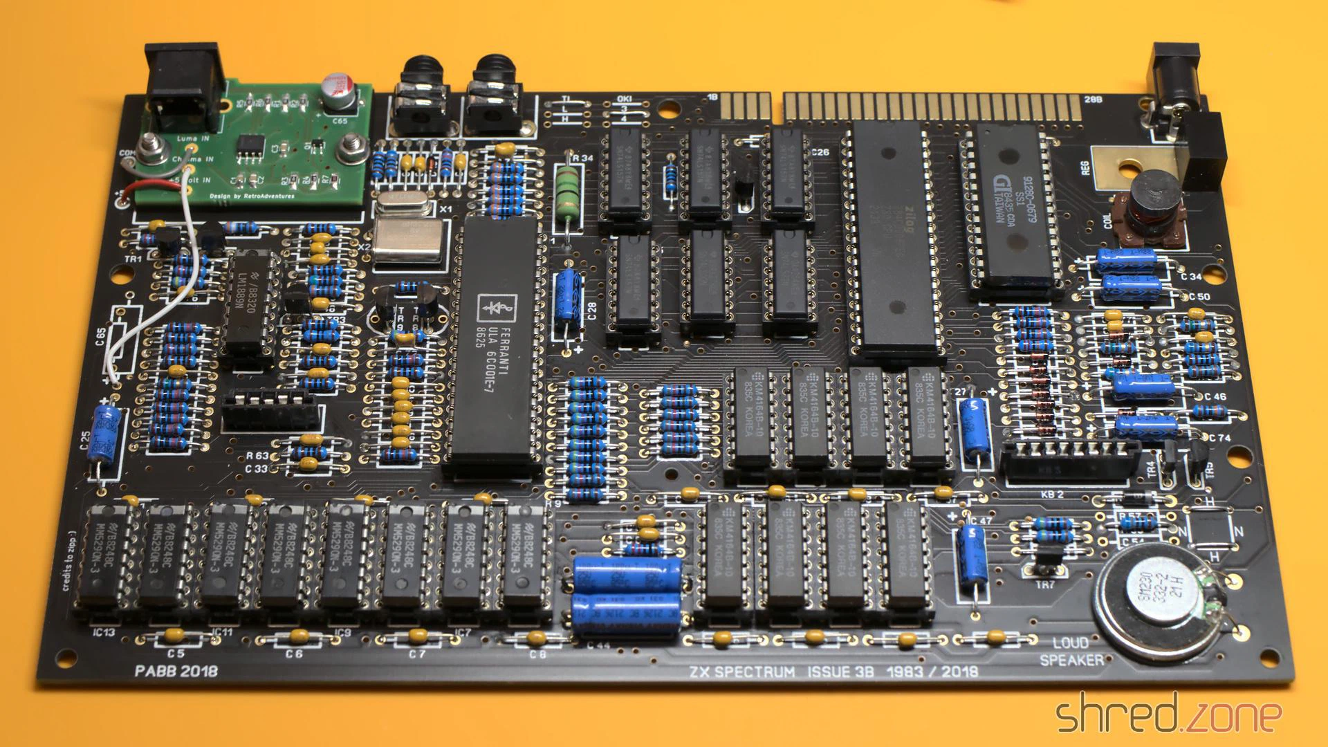
After that, the new board was finally finished and ready for a first test.
Bug fixing
So, power on, and then I saw this:
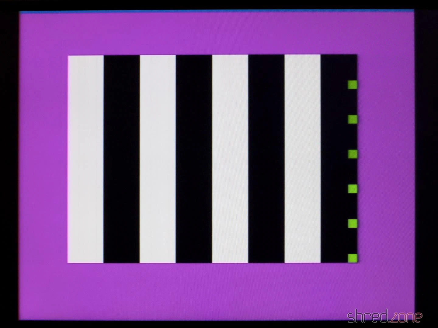
The diagnostic module showed no activity on the CPU bus control lines. My suspicion was confirmed when I checked the CPU clock input with an oscilloscope. Only a flat line could be seen there.
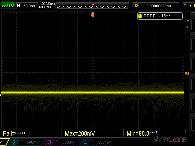
The CPU clock is generated by the ULA, but the clock signal was present there.
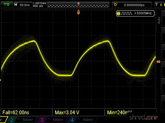
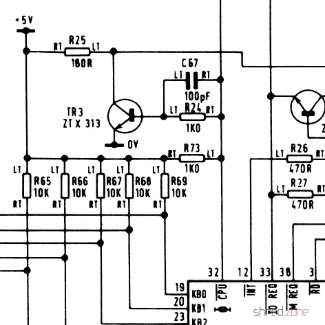
A look at the schematic shows that transistor TR3 is located between the ULA clock output and the CPU clock input, probably to amplify the signal. Strangely, the signal to the right of R24, which is directly connected to the clock output, was still present. However, to the left of R24 (connected there to the base of the transistor), the signal was missing. When I removed TR3, the clock signal appeared there too, so TR3 had to be the cause.
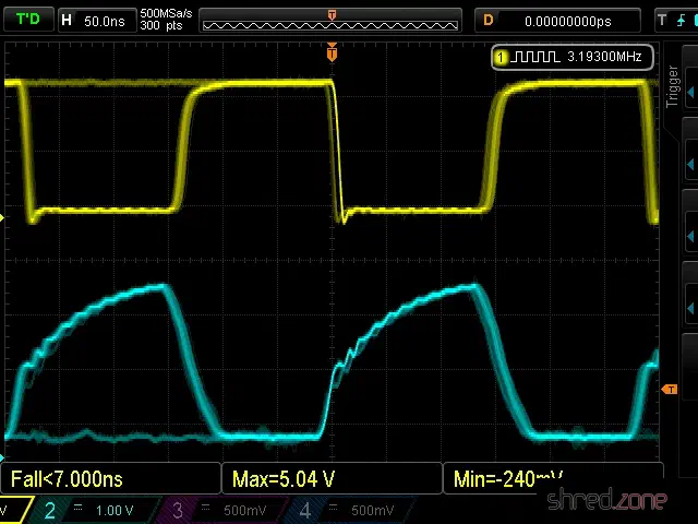
After a longer search, I found out that the Spectrum is very picky about the type used for TR3. The original ZTX313 is no longer manufactured, so I first used a BC548, which was recommended as a replacement type in other places. For TR3, however, the only recommended replacement type is the MPS2369, which is now also hard to come by. With this type, the clock signal was finally fine (cyan: ULA clock output, yellow: CPU clock input).
To my delight, the new Spectrum then started up and showed the famous start screen.
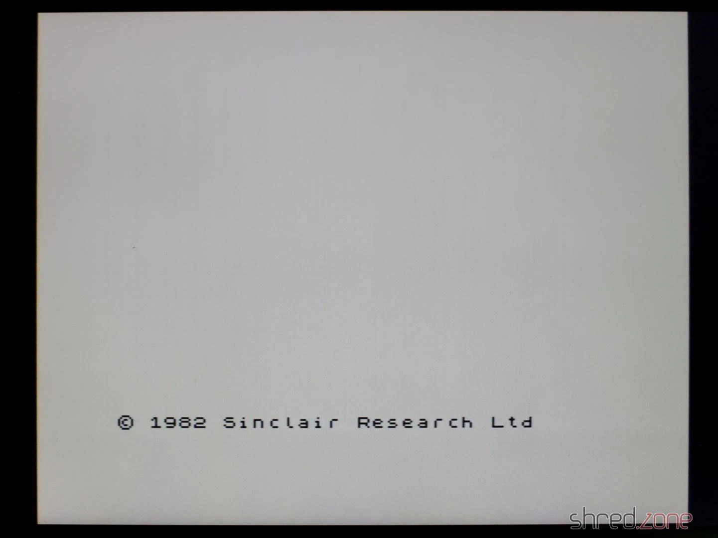
As the next step, I carried out a complete diagnosis. Now I got the error that the M1 signal was missing.
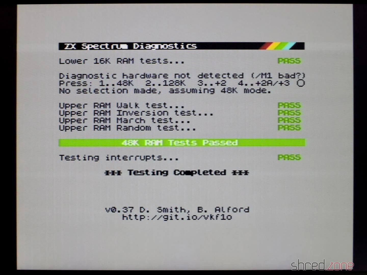
The M1 signal is generated by the CPU and indicates the first of four machine cycles in which the next instruction is read in. The Spectrum itself does not use the M1 signal, but a few expansions like the ZX Interface 1 require it.
After replacing the CPU, all diagnostic checks were finally passed.
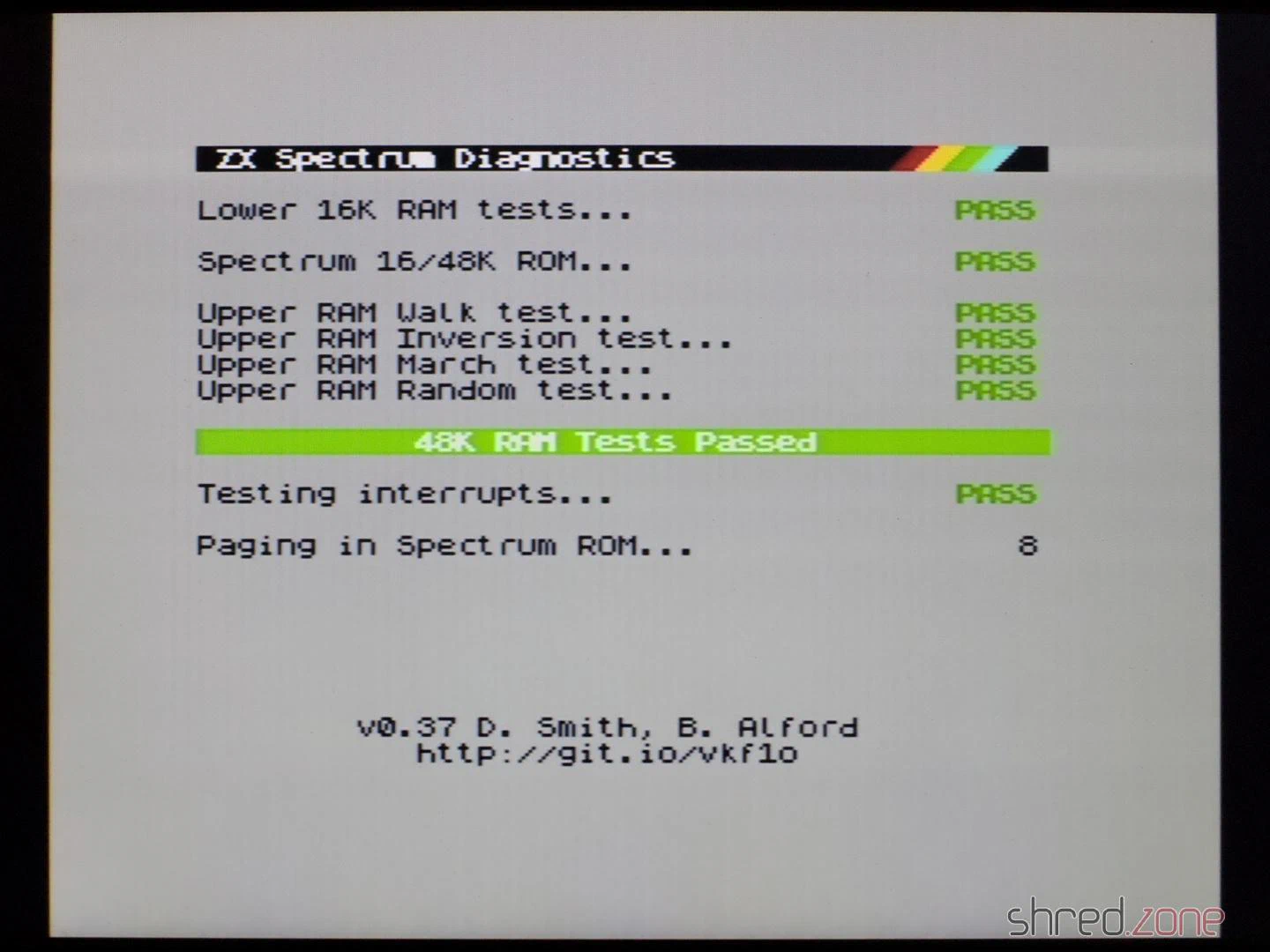
In the end, I could only reuse the ULA, the ROM, the LM1888N and the coil from the old ZX Spectrum. I had also hoped for all the RAM chips and the CPU, but I had less luck with those.
Test run
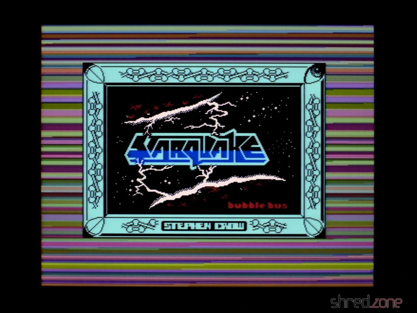
Anyway, it was finally time for a test run. I connected the new Speccy to my computer and used tzxplay to load my favourite game, Starquake. It loaded and ran perfectly. The picture quality of the S-Video output is also excellent, probably the best you can get out of this old design. Only the ZX Spectrum Next with its digital and pixel-perfect HDMI output has even better quality.
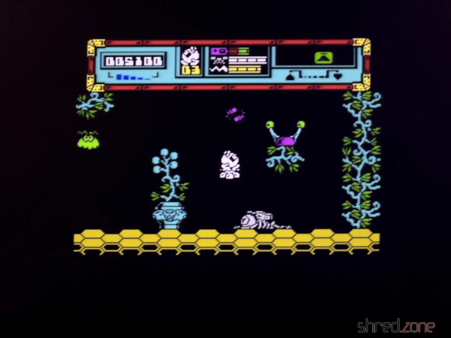
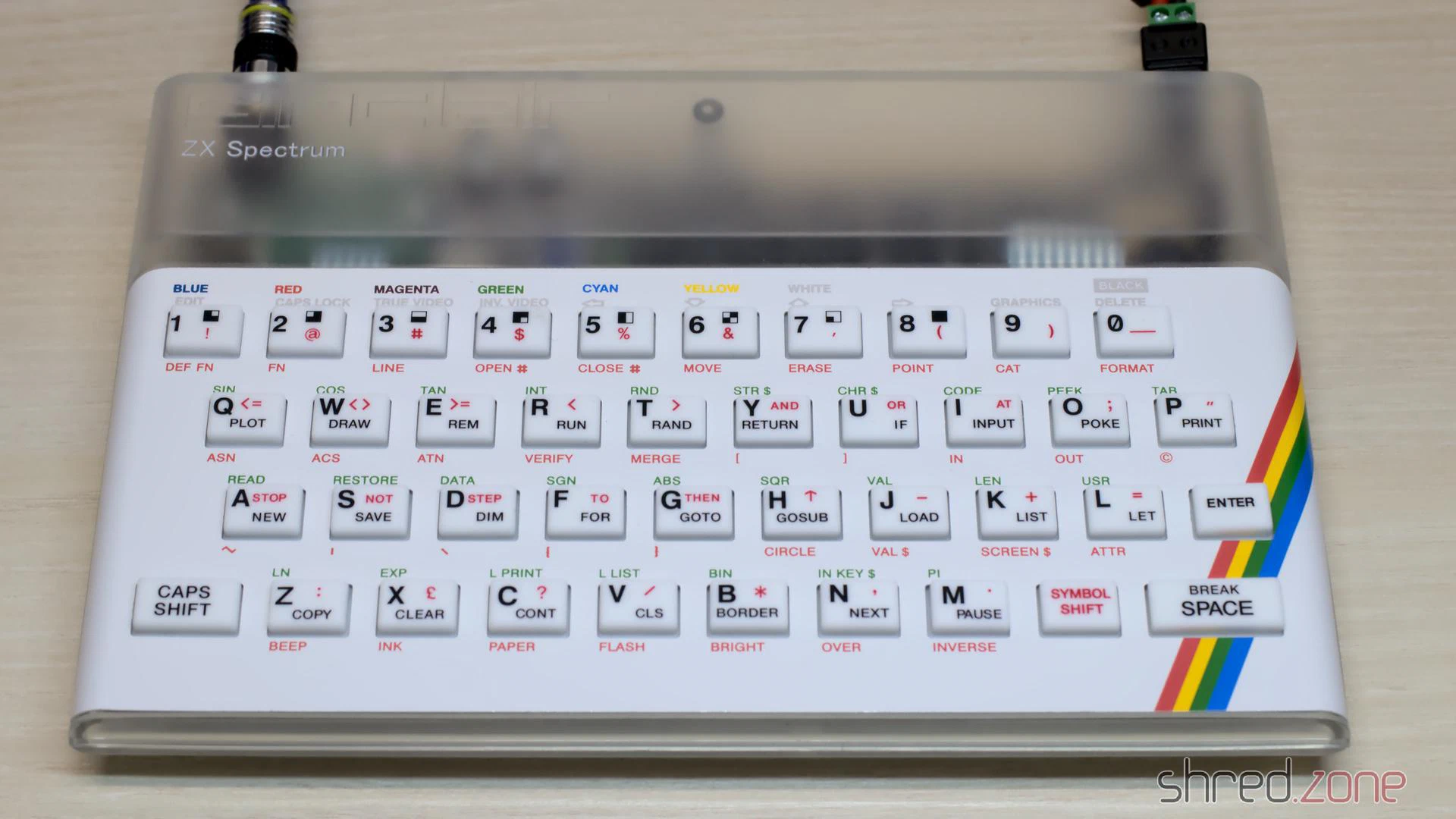
I got the original board without a case. But luckily, there are replica cases, keyboard mats, membranes and faceplates on the market, with which you can assemble a brand new exterior. Of course, I chose a transparent case so that you can admire the beautiful black motherboard from the outside. Well, at least a little bit.
And here it is, a ZX Spectrum in practically new condition.
The Superfo Harlequin is a ZX Spectrum 128K clone. It is special because even though it’s a 128K Spectrum, it still fits into an 48K Spectrum case. It’s also special because the ULA custom chip is replicated by discrete 74HC-type standard chips that can be replaced easily if one of them should get broken. It’s just a small advantage though, because the RAM chips, sound chip, and Z80 CPU are rare by now.
I have ordered the Harlequin 128K Black Large DIY Kit at ByteDelight. It comes with all components that are required to build the main board, even those that are difficult to find elsewhere. There is also a Flash ROM chip enclosed in the kit, but it does not contain a Sinclair ROM image for license reasons. What’s still required to build a complete Speccy is a ZX Spectrum case with keyboard, and a Flash ROM programmer for the Sinclair ROM.
Assembling
The Harlequin has only a single SMD component, and that one was even presoldered. All the other components are through-hole, so this DIY kit is even suitable for soldering novices.
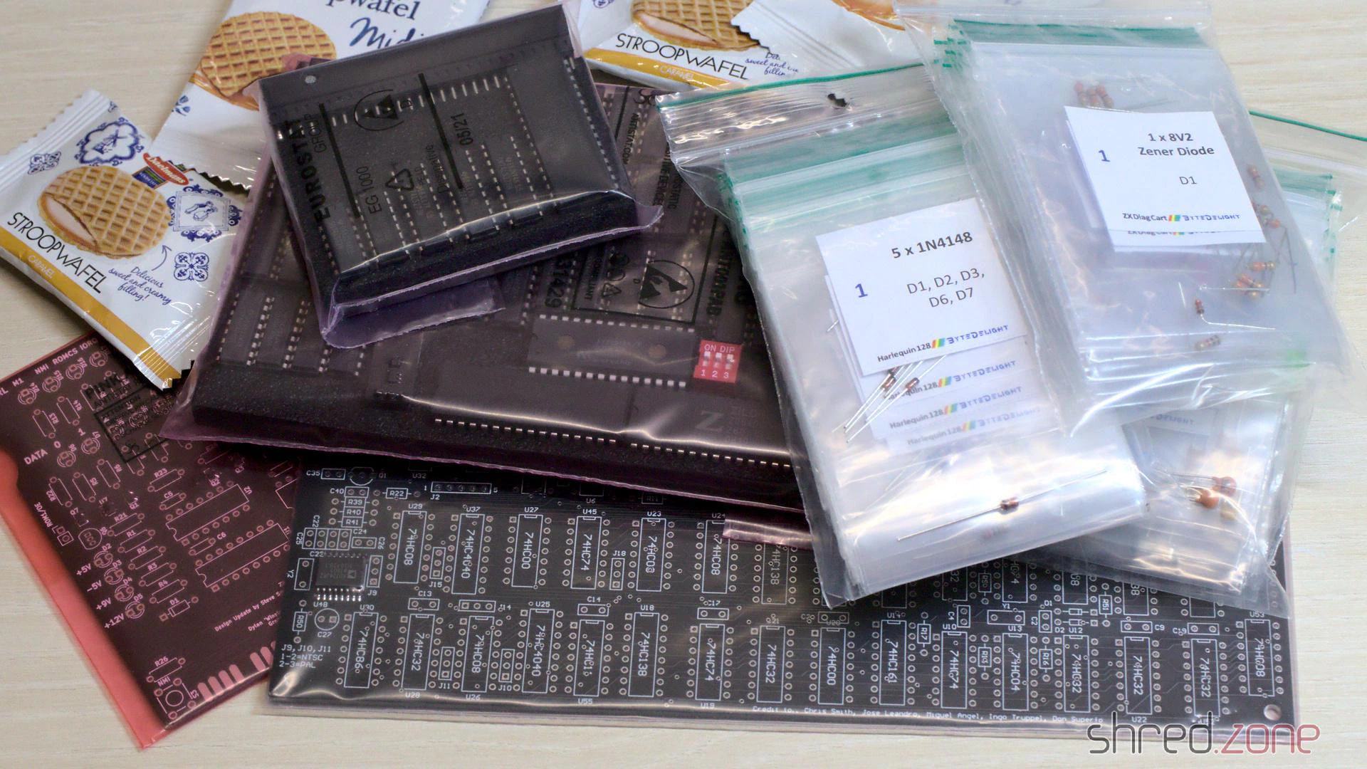
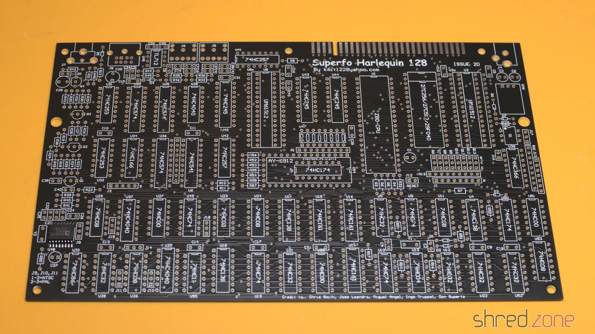
I spent the rest of the day with getting the components out of their bags, locating their correct location and then soldering them in. The ByteDelight kit was carefully assembled. Every component comes in separate bags per value, and are enumerated in their optimal order for assembling. It’s literally just soldering by numbers. 😄
The most boring part was to solder in all the 51 sockets. The DIY kit came with standard sockets, but I generally prefer turned pin sockets, so I used that ones instead.
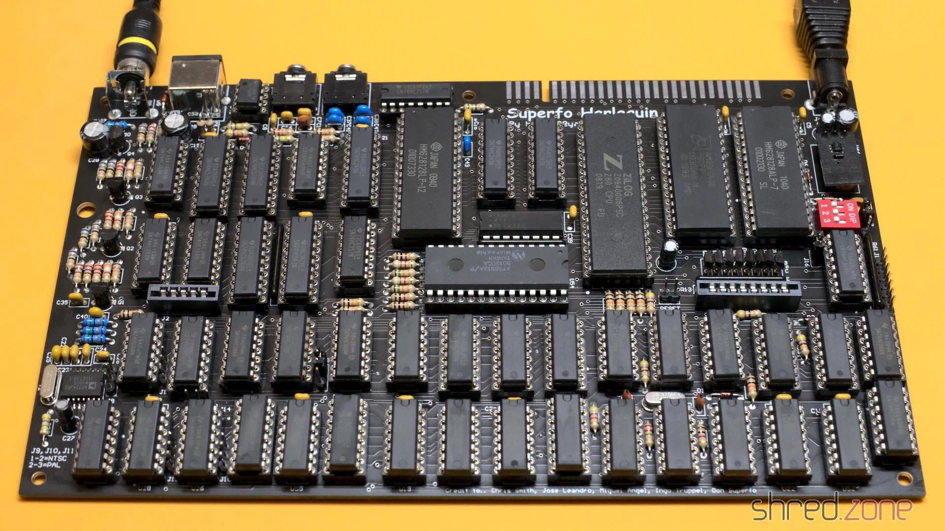
The kit also contains the crystal that is needed for an NTSC setup, so you can choose between a PAL and NTSC machine. The board itself is pre-configured for PAL though. For an NTSC machine, a few traces at the bottom side of the PCB need to be cut.
Flashing the ROM
The DIY kit comes with an AMD AM29F040B Flash ROM. It is large enough to contain up to 8 ROM images. A DIP switch selects the image to be used. The pre-flashed image contains a Diag ROM, some other software, but no ZX Spectrum ROM for license reasons. The board itself also supports original Spectrum 48K and 128K ROMs, as well as 27C256 and 27C512 EPROMs.
ROM files can be found on the internet. I decided to keep the first six Flash ROM banks, and use bank 7 for a Spectrum 48K ROM, and bank 8 for a Spectrum 128K+2 ROM.
For flashing, I use the XGecu TL866II+ programmer and the minipro open source software. First I read the original content of the Flash ROM:
minipro --device 'am29f040b@DIP32' --read harlequin.bin
Then I made a copy of the first six banks. It’s easy with the dd command. With a block size of 65536 bytes, the banks can be selected with the skip and count options. To keep the first six banks:
dd if=harlequin.bin of=harlequin-6banks.bin bs=65536 count=6
After that, I use cat to compile a new binary. Note that each bank must be 65536 bytes large, so if a ROM image is smaller, it must be duplicated (or quadruplicated):
cat harlequin-6banks.bin \
  48k.rom 48k.rom 48k.rom 48k.rom \
  128k+2.rom 128k+2.rom \
  > harlequin-new.bin
The new image can then be burned to the Flash ROM:
minipro --device 'am29f040b@DIP32' --write harlequin-new.bin
With the Flash ROM inserted into the Harlequin board, it was finally completed and ready for a first start. Unfortunately the maker of the Harlequin board saved a rectifier bridge, so it’s still important to take care for the correct polarity of the power plug. Like the ZX Spectrum, the Harlequin needs a power supply with a 5.5/2.1 mm barrel plug with center negative. Most power supplys on the market are center positive.
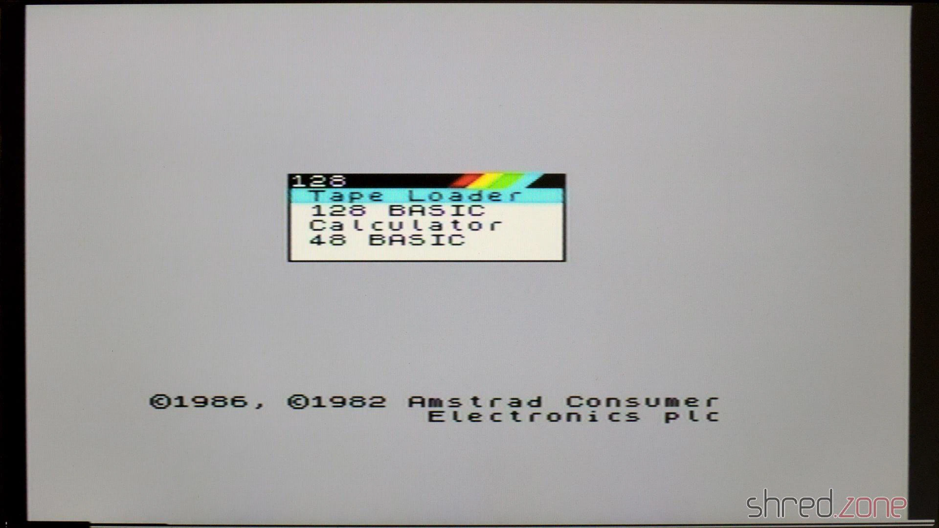
Even though the Harlequin has a lot more chips than an original ZX Spectrum, it is very frugal. It only consumes 1.7W at 9V, while the original Speccy consumes 4.8W. On the other hand, the Harlequin does not need 12V and -5V to run, so these voltages are not generated. This might be a problem for a few very exotic expansions.
The Case
The DIY kit only comprises everything that is needed to assemble the main board. What’s missing is a case with keyboard, and a power supply. The board has the same dimension as an original ZX Spectrum 48K board, so you can use original cases (e.g. the standard “rubber key” case or the ZX Spectrum Plus case), or buy a new replica case with new membranes, keymat and faceplate. The latter case is more expensive, but you get a brand new case in return, and you can pick from a large variety of colors.
I decided for a white keyboard, and a transparent case so one can still admire the beautiful Harlequin board even inside a closed case.
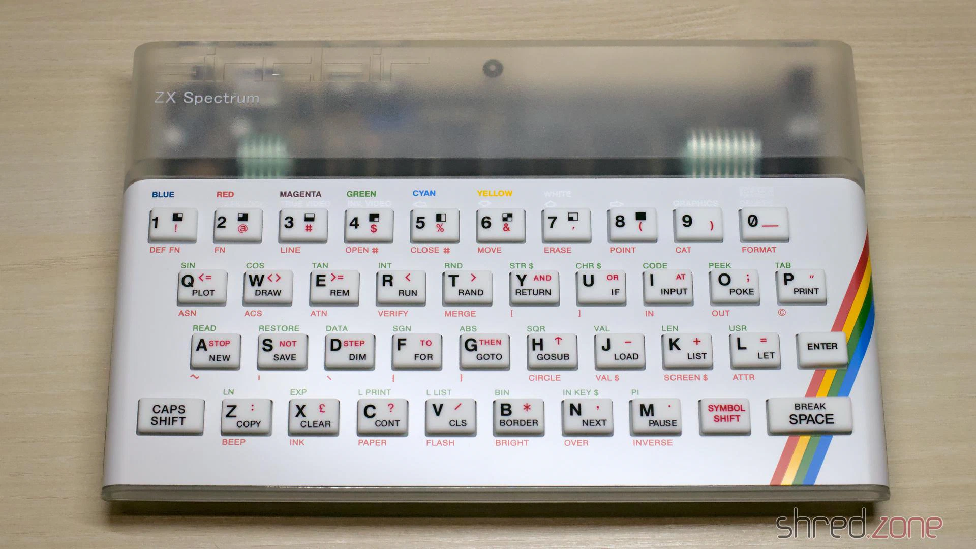
The Harlequin has a separate RGB mini DIN connector. It is made in a manner so it won’t interfere with a classic case. However you might want to use the RGB connector as it offers a much better image quality. Shops like ZX Renew offer special Harlequin cases with a cutout for the RGB connector. If you want to use a classic case, you might need to cut out a bit of the beautiful old case to access the connector.
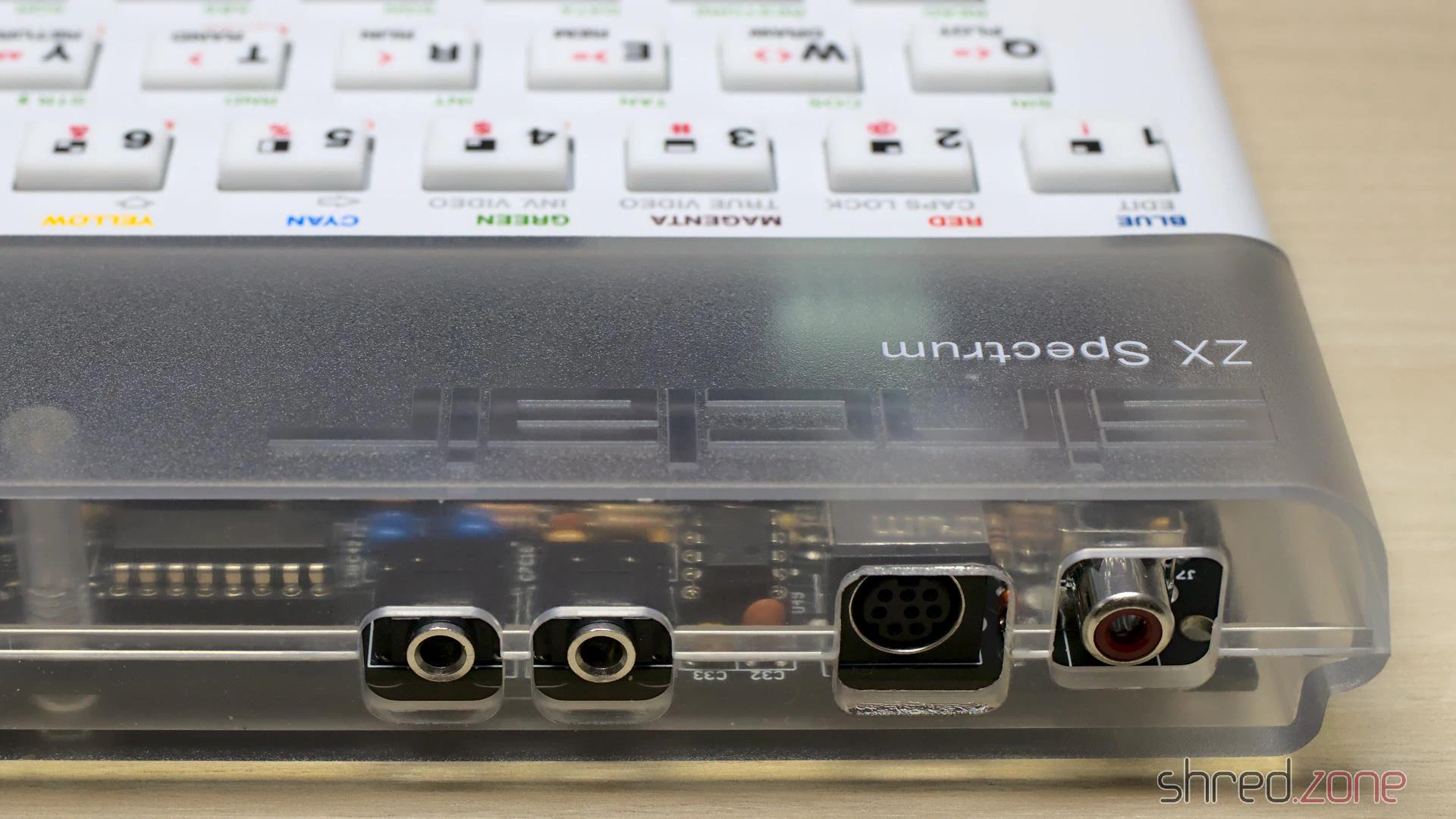
Since we are talking about making holes into old cases: The Harlequin has a built-in joystick interface. If you want to, you can cut out a space for a 9 pin Sub-D male connector, and wire it to the board. I refrained from making a cut into my beautiful Harlequin case, and use a classic Kempston joystick interface instead.
Let’s Play
The simplest way to load software into the Harlequin is by the Mic/Ear port. There are smartphone apps and also a lot of tools that can generate the sounds to load TAP or TZX files, so there is no need to dig out the old tape recorder and audio cassettes.
I am using my tzxtools. The tzxplay command plays back TZX and TAP files to the standard audio output. I connect the sound card output to the mic/ear connector using a classic phone jack cable.
Since the Harlequin is a full-featured 128K clone, it also comes with an AY-3-8912 sound chip and even a stereo output. So the first thing I did was loading a game that makes use of that soundchip for in-game music.
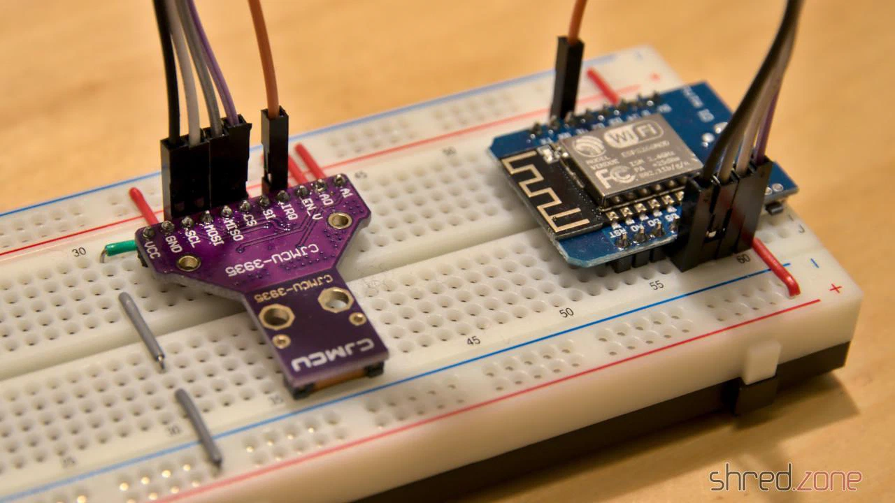
The sensor module can be found at many online shops selling products from China. It is not really cheap, but still affordable. I decided to use an ESP8266 as microcontroller, so I can read the sensor data by WLAN. The sensor is connected to the ESP via SPI. There was also some space left for a SK6812 RGBW LED indicating the sensor status.
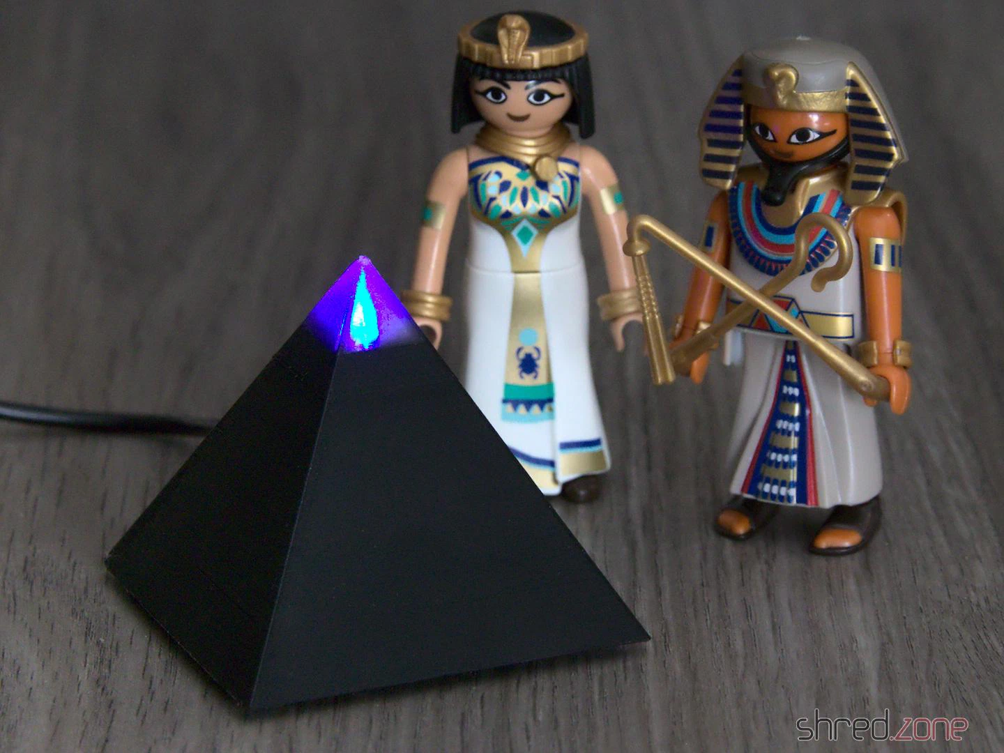
The result of this project can be found at Codefloe. It’s called Kaminari (which is Japanese for lightning), and also comes with OpenSCAD files for a 3D printed, pyramid shaped case with illuminated tip. In this article I will explain a bit about how I developed the Kaminari firmware.
UPDATE: Meanwhile I have removed the pyramid case from the project. The reason is that in that case, the ESP and the sensor are too close together, so the ESP’s WiFi antenna was massively disturbing the sensor. There is no replacement case.
The first problem was the calibration. The sensor is roughly pre-calibrated, but must be fine-tuned to 500 kHz ±3.5% via the TUN_CAP register. For this purpose, the antenna frequency can be routed to the IRQ pin and then be measured by the ESP. I chose to prescale the frequency by a ratio of 128, giving an IRQ frequency of 3,906.25 Hz. For measurement, I’ve set an IRQ handler that is just counting up a variable on each interrupt. I then reset the counter, wait for 1000 ms, then read the counter, and get the IRQ frequency in Hz units. It’s not 100% accurate, but good enough for this purpose.
The TUN_CAP register offers 16 calibration steps. Just incrementing it until the frequency matches, would take up to 16 seconds. Instead I used an algorithm called successive approximation to find the correct calibration value in only 4 iterations, taking a quarter of the time.
TUN_CAP register useless.The next problem is finding a good noise floor level. This is some kind of background radio noise filter. If the level is too low, the sensor cannot operate properly because of interfering background noise. If it is set too high, the lightning detection quality declines.
The noise floor level cannot be calibrated just once at the start. Radio noise sources come and go, may it by turning on an electronic device or just by a change in the weather. I did some experiments, and the most promising solution is a kind of tug-of-war. When the AS3935 detects too much noise, it triggers an interrupt, and the noise floor level is raised to the next higher step. If the last level change was 10 minutes ago, the ESP attempts to reduce the level by one step.
In order to reduce the number of level changes, I have added a counter. Each noise interrupt increments the counter, and every 10 minutes the counter is decremented. The level is raised when the counter reaches 2, and lowered when the counter reaches -2.
Sometimes I noticed a “noise level runaway”, where the AS3935 triggers a lot of noise interrupts in a very short time, raising the noise floor level to its maximum value immediately. To stop that behavior, further noise interrupts are being ignored for one minute after a noise interrupt has been processed.
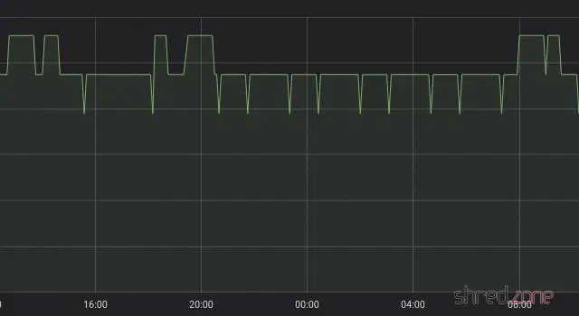
Now the noise floor level has settled to an average of 95 µVrms here. In the graph, one can see that the level is raised at some time, but then reduced again after a while. One can also see the frequent attempts to lower the level a bit further, immediately followed by a raise back to the average level. It seems that the AS3935 and the ESP have negotiated a good compromise. 😉
The AS3935 seems to be set up in an optimal way now, but I still get some false lightning events from time to time. There are a few registers left to experiment with, namely WDTH (watchdog threshold), SREJ (spike rejection) and MIN_NUM_LIGH (minimum number of lightning). I have raised the watchdog threshold to 2, and did not have a false lightning event since then.
Now I have to wait for some real lightnings… 😄