However, they were quite inconvenient. Cassettes were slow. It took several minutes for a game to load. With a “collection” of several games on one cassette, you first had to fast-forward to the right spot, which wasn’t that easy, as the noise of the data stream sounds pretty much the same to us humans. You could write down the counter readings on the cassette recorder, but the counters weren’t standardised, making the index tied to a specific model.
When I finally got my Amiga with a floppy disk drive, I quickly forgot the times when I had to fiddle with cassettes.
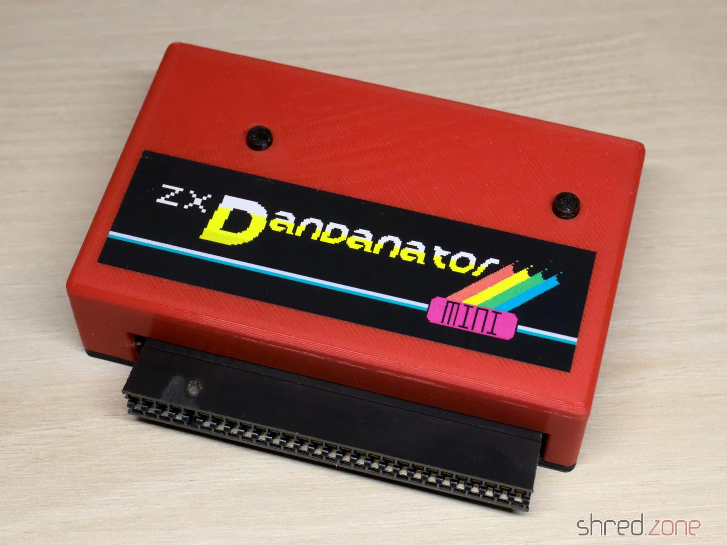
Today I own a few ZX Spectrums, but no cassette recorder anymore. To load software into the computer, I usually use my PC’s headphone jack and tzxplay. But there is a more elegant way. The ZX Dandanator Mini by Dandare is an expansion with 512KB of flash memory where your favourite games can be saved. A boot menu allows you to select one of these games. It is then loaded directly into memory. The Dandanator also offers a Kempston-compatible joystick port.
While assembling my ZX Dandanator Mini, I noticed that the project’s documentation left a few questions unanswered. I hope my blog article will help others with building their own.
Parts
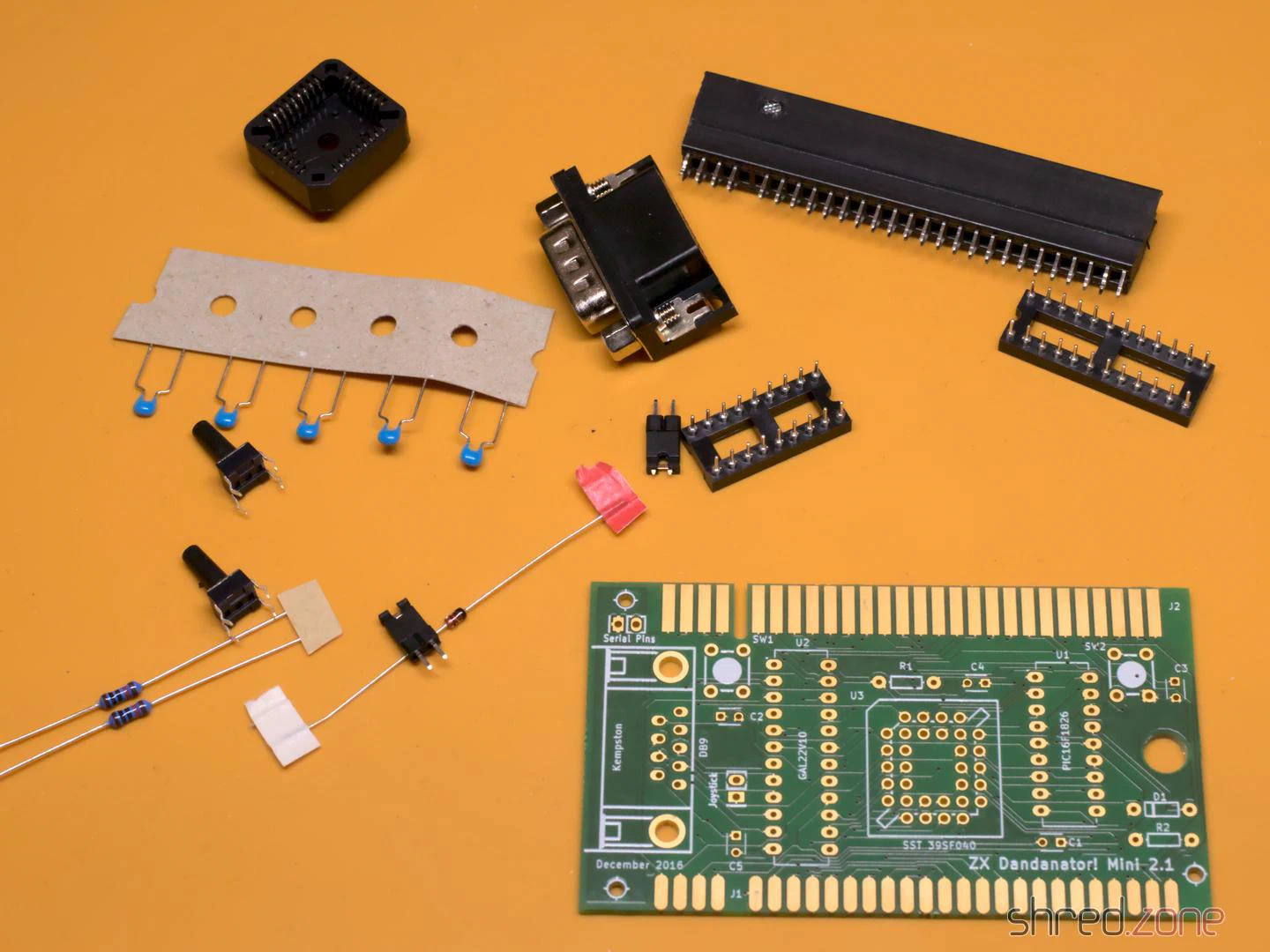
- 1x GAL 22V10 (+ DIP20 socket)
- 1x PIC 16F1826-I/P (+ DIP18 socket)
- 1x SST 39SF040 Flash ROM (+ PLCC32 socket)
- 1x 1N4148 (TH)
- 2x 10kΩ resistors (TH)
- 5x 100nF ceramic capacitors (TH)
- 1x D-Sub connector, 9-pin male, angled, European style (e.g. this one)
- 2x pin headers, 2-pin
- 1x jumper
- 2x tactile switches, 6 mm high (17 mm for the 3D-printed case)
- 1x PCB (Gerber files are here)
- 1x ZX Spectrum Edge Connector (can be found in retro shops, online marketplaces, or DIY)
- 1x 3D-printed case (optional)
You need a programmer capable of flashing the PIC, the GAL, and the Flash ROM (e.g. the XGecu TL-866II Plus with PLCC32 adapter). I also recommend a good PLCC extraction tool.
Classic GALs are no longer produced, but can still be ordered as NOS parts on online marketplaces. A replacement that is still being produced is the Atmel ATF22V10C-10PU. However, you will then additionally need a 3.3kΩ 6-pin resistor network (more on this below).
Assembly
The assembly is straightforward. You start with the flattest components and work your way up to the tallest ones. There are no SMD components, so even a soldering beginner shouldn’t have any problems.
Make sure the sockets are aligned correctly. Unfortunately, there are no markings for pin 1 of the two DIP sockets on the silkscreen. They should be aligned with the notches facing towards the buttons, as seen in the photo. The PLCC socket should match the outline on the silkscreen.
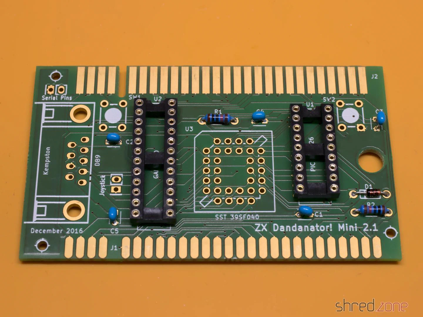
The edge connector is normally meant to be soldered upright, not to the edge of the PCB. So the pins must first be bent inwards on both sides until the connector sits centrally and all pins touch the pads of the PCB. Also, make sure to solder the connector to the correct side of the PCB; that’s the one with the short pads. The connector on the other side is intended for further expansions, such as a joystick interface, but you could even stack several Dandanators together.
If you intend to use the 3D-printed case, leave a gap of about 2 mm between the PCB edge and the connector.
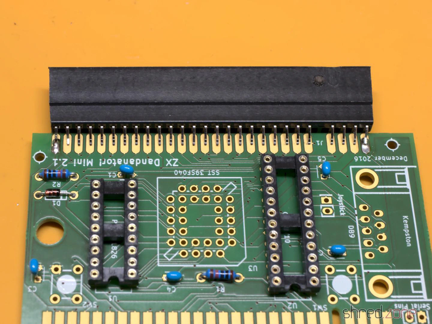
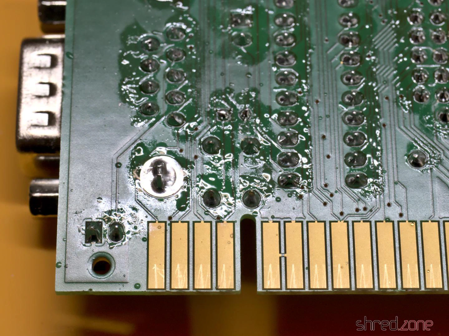
Some of the pads are close to the edge connector on the back. It’s easy to accidentally spill a few drops of solder onto the pads while soldering. A piece of Kapton tape can easily protect them.
One problem with the ATF22V10C is that it doesn’t have internal pull-ups on the inputs. This means the inputs float when no joystick is connected. This causes problems. On my system, the first game in the list was always started immediately when no joystick was connected. A possible solution is to solder a resistor network onto the bottom side. The resistors are connected to pins 8, 9, 10, 11, and 13 of the ATF22V10C. The common bus is soldered to pin 24. Be careful not to bridge or short-circuit adjacent pins.
This problem shouldn’t occur with the ATF22V10B, but at the time of writing, this variant was either sold out or absurdly expensive.
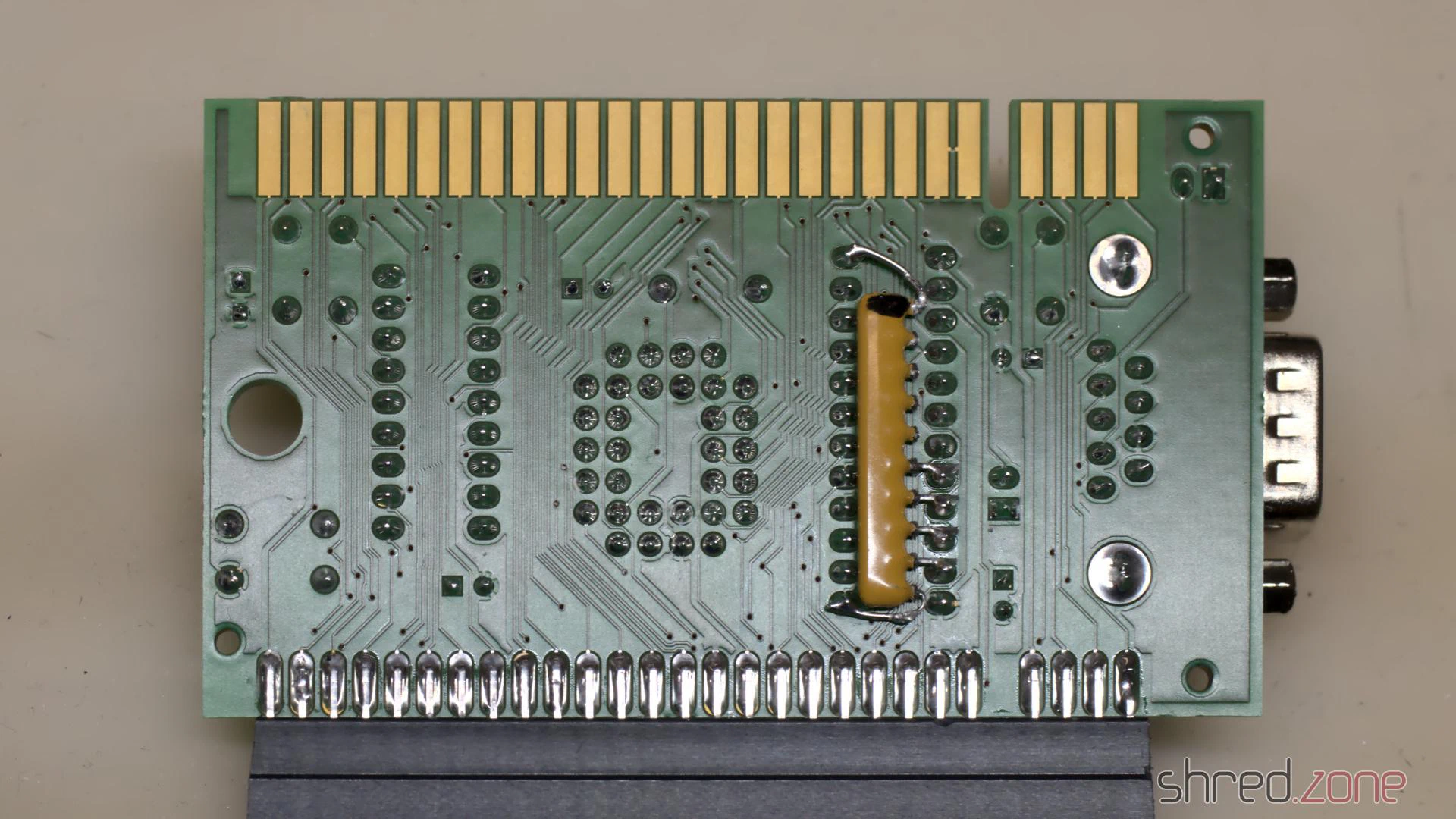
Although this problem probably doesn’t occur with older GALs, the manufacturers still recommend not leaving input pins floating. In my opinion, the pull-up resistors should have been part of the Dandanator design.
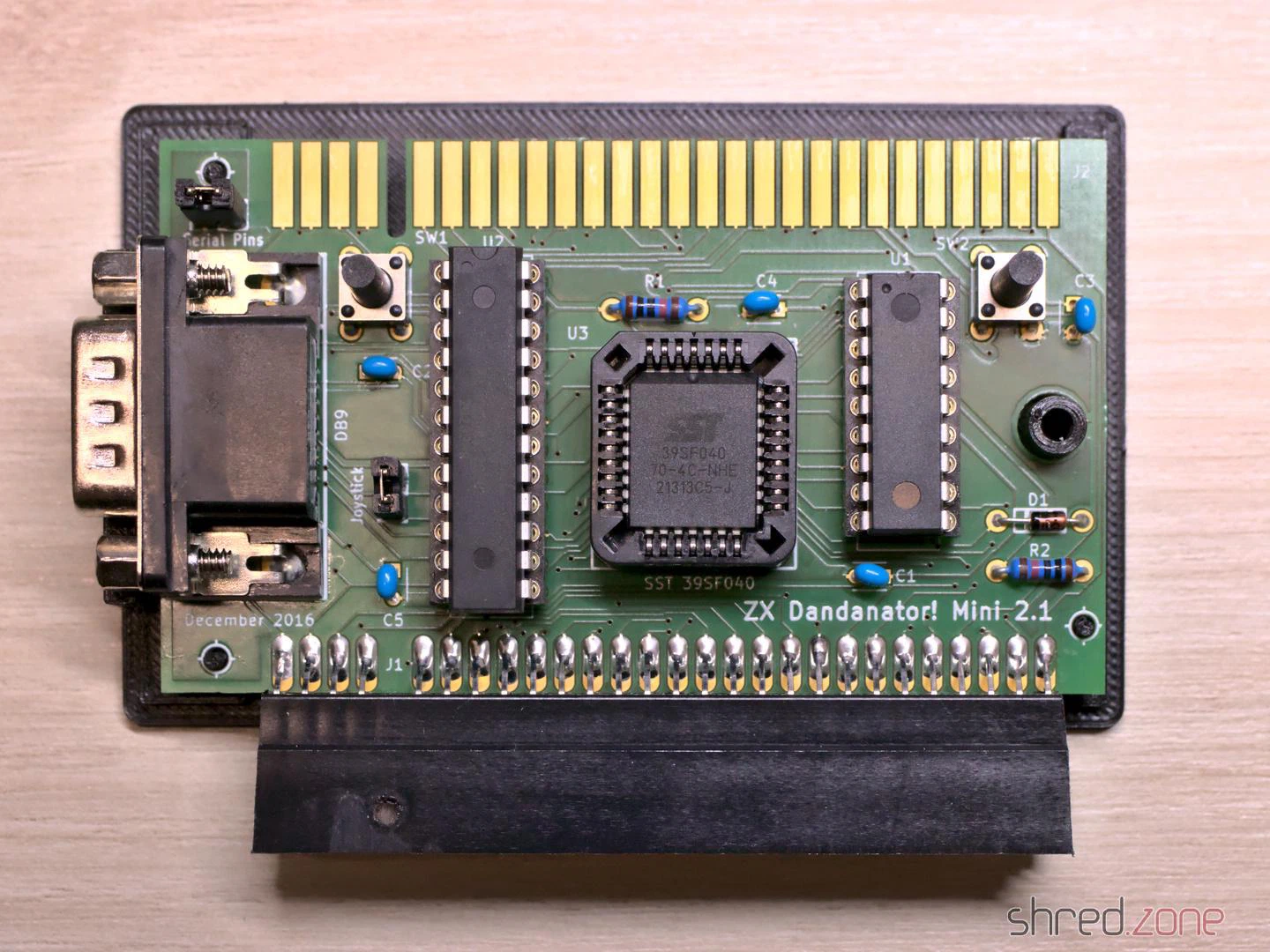
In the final step, you clean the PCB and check it for solder bridges and other faults. A short circuit can destroy the voltage regulator in the ZX Spectrum, which is relatively difficult to repair.
The “Joystick” jumper is there to activate the joystick port. It should be closed if no other joystick interface is used. The “Serial Pins” jumper seems to be intended for in-circuit programming and should not be closed. (Nothing will break if you accidentally close it, but then the joystick will be permanently pressed to the right.)
Once the assembly is complete, the next step is to program the chips. They are all programmed differently.
Flashing the chips
- GAL: The fusemap can be downloaded here. If you are using an ATF22V10 and the XGecu programmer, make sure you select the
(UES)variant as the chip type. - PIC: An initial firmware can be downloaded here. I tried flashing it with the minipro software, but couldn’t get a working PIC this way. Ultimately, I used the original software from XGecu.
- Flash ROM: The Flash ROM contains the games and also pokes. The image file is generated by a ROM Assembler tool.
The ROM Assembler is written in Java, so it runs on every modern operating system. If you know your way around Java, you can easily compile the latest version yourself from the source code. You can also download a jar file from the Dandanator download page and run it using the command java -jar dandanator-mini-*.jar.
The GUI of the ROM Assembler is fairly self-explanatory. You can simply drag and drop TAP, SNA, Z80, and POK files of your favourite games into it until the flash memory is full. In the settings, you can change the font and language, and even use a custom background image.
Many games can be found at World of Spectrum. An extensive collection of POK files is available here.
Once you have put together your favourite games, create a ROM image and write it to the Flash ROM.
Let’s play!
The Dandanator is connected to the ZX Spectrum’s expansion port. Remember to unplug the computer from the power first.
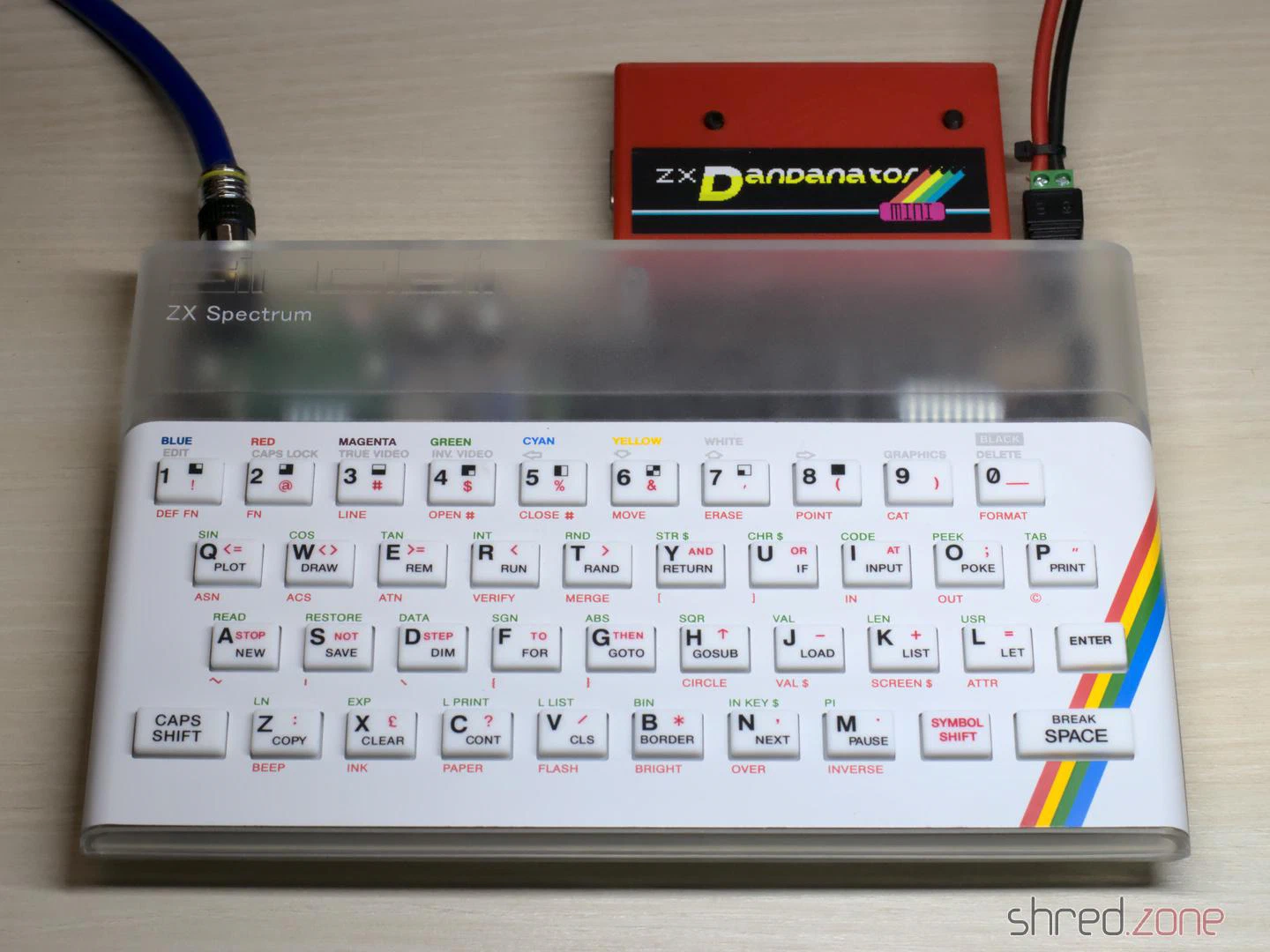
Now switch on your Speccy and press the right button on the Dandanator to reach the main menu.
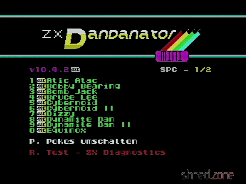
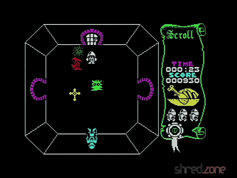
You can select a game, either by using the joystick or pressing the corresponding key, then select the pokes to apply, and finally start the game.
When using the Dandanator for the first time, you should turn the Speccy off, then hold down both buttons and turn it back on. The Dandanator will then flash the latest firmware version to the PIC.
The right button always takes you back to the main menu. The computer no longer needs to be reset.