From my first days of home computing, I still have two ZX Spectrum 48K. The first one is my own one, which I restored in the previous part. This second Speccy was a donation from a friend. It was broken and written off as irreparable, so he wanted to throw it away, but I asked him to give it to me instead.
Let’s find out what we have here…
Memorable Surprise
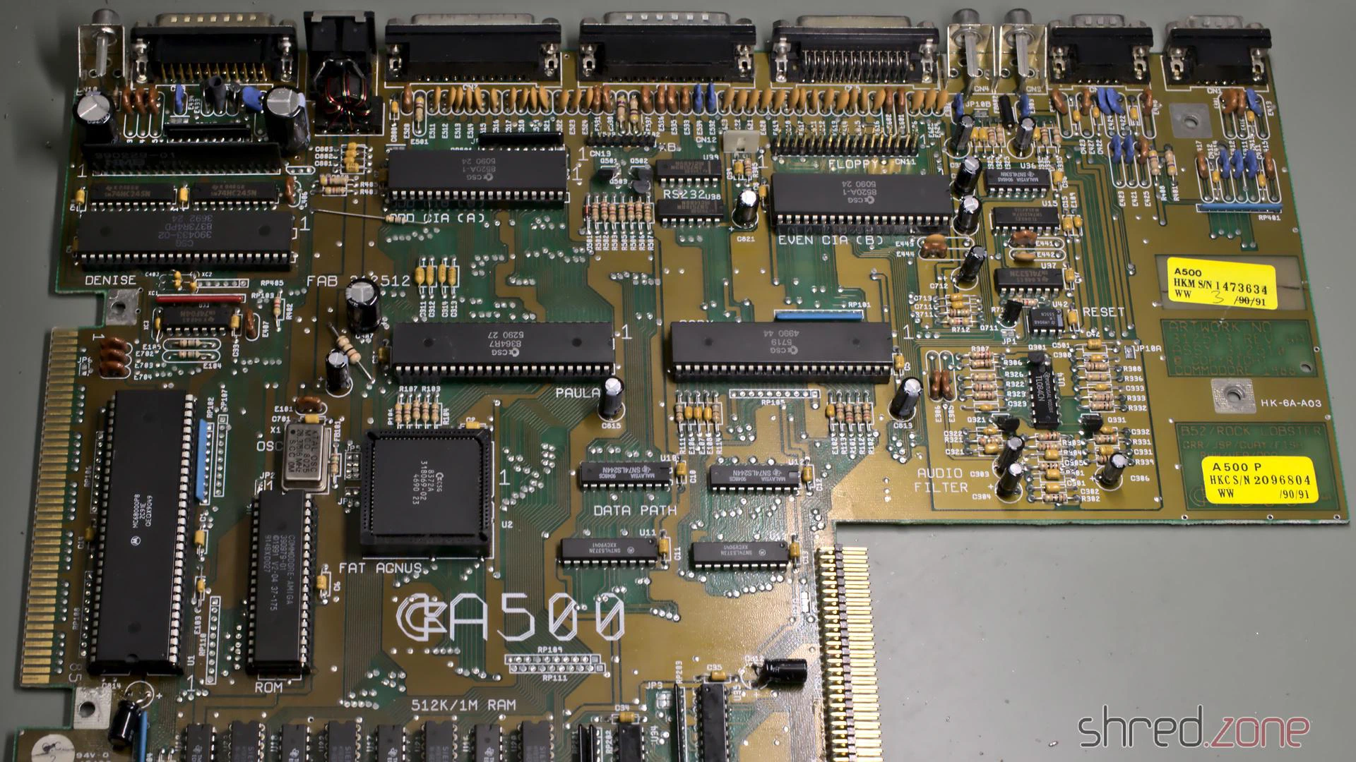
This Speccy also has an Issue Two board, but it seems to be a bit older because it has an older ULA 5C112E-3, while my own one has an ULA 6C001E-6.
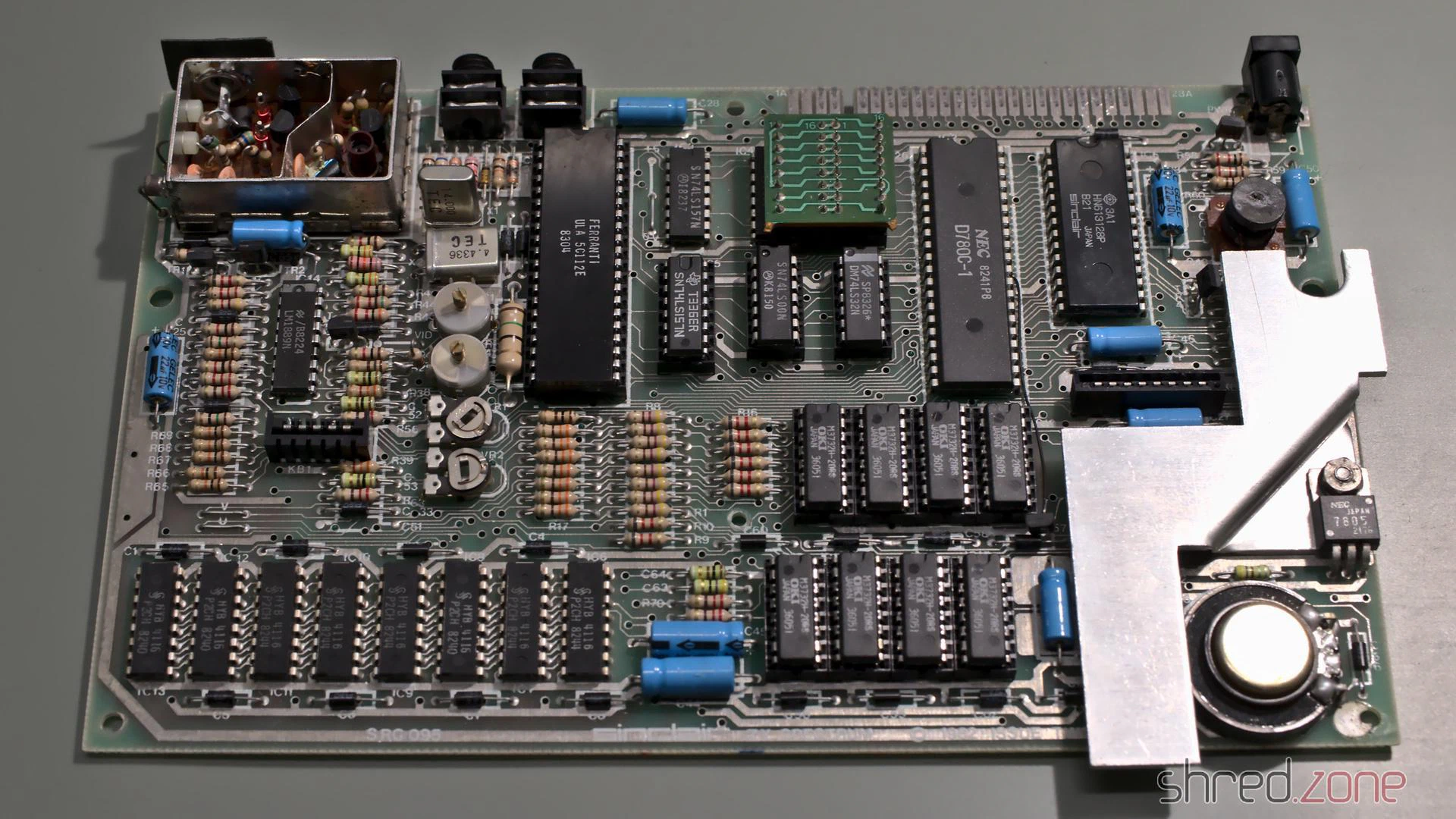
What surprised me was the tiny daughterboard that is used for IC26.
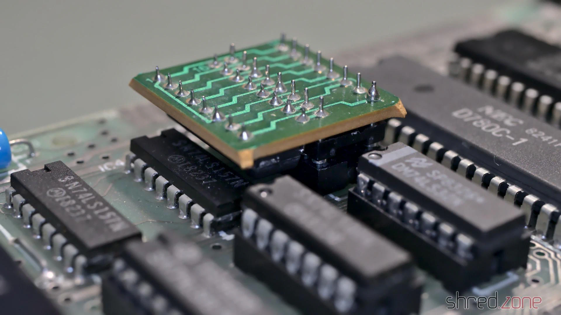
I first thought it was some kind of post-production fix for a PCB error, but it turned out to have a much simpler explanation. For the upper 32K RAM, Sinclair used eight 32KBit DRAM chips of various manufacturers. Those chips were actually 64KBit chips, but one half of the memory turned out to be defective after production, so they were sold with half of the capacity for cheaper.
To run a Spectrum, all eight of the chips need to have the defect in the same half. A wire bridge on the board then configured whether the “upper” or “lower” half of the RAM was to be used. For the OKI M3732 chips that were used on this board, the internal memory cell addressing is a bit different though. Let’s put it that way, on these chips either the “left” or “right” half was defective. The tiny daughterboard just takes care of the necessary modification on the address lines to run the OKI chips. Maybe they have just been the cheapest around when Sinclair produced this batch. Starting with the issue 3 boards there were jumpers for the OKI chips, and the daughterboard was not needed any more.
Damage Assessment
In order to see anything, I first did the “composite mod” that I also did on my other ZX Spectrum. It just needs a wire and a few minutes of work, so it is well invested time even if this ZX Spectrum actually turns out to be irreparable.
After that, I connected the Speccy to the TV, took a deep breath, and then turned on the power.
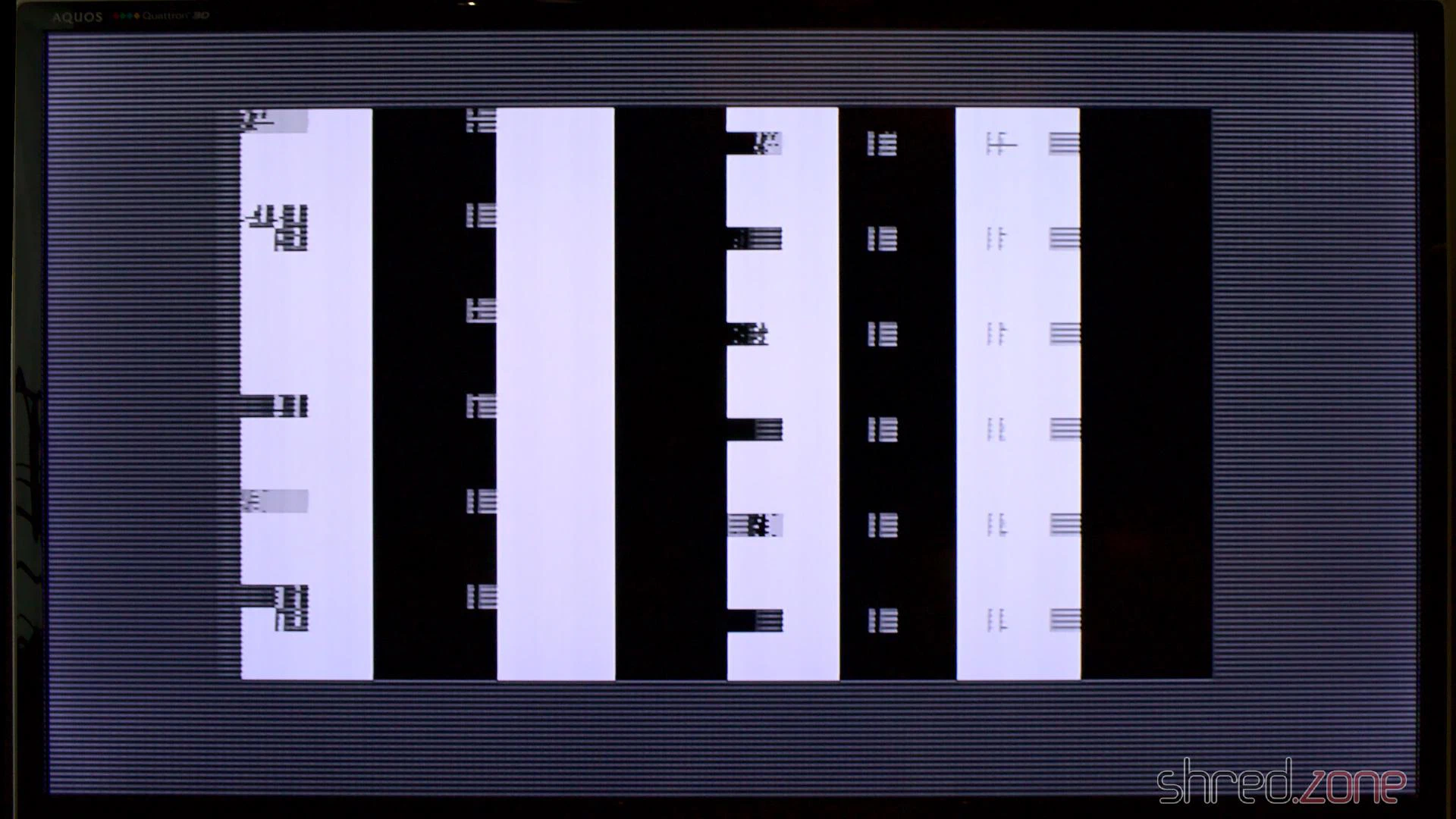
Yes, this computer is definitely broken.
New Coil
The first thing that should be tested on a broken ZX Spectrum is if the voltages are correct. The 4116 RAM chips need three of them: +5V, +12V, and -5V. The +5V were there, but instead of +12V I only got +7V, while the -5V were completely missing.
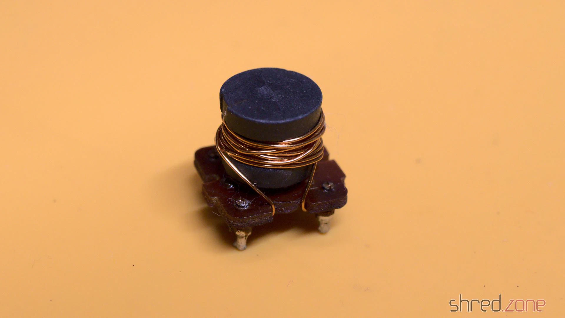
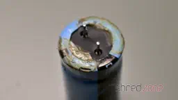
With further checks I found the culprit: the coil was shortened. And there must have been a lot of heat involved, as the insulation plastics was completely melted and got a dark purple color. The left photo shows this coil, the right one shows a good coil for comparison.
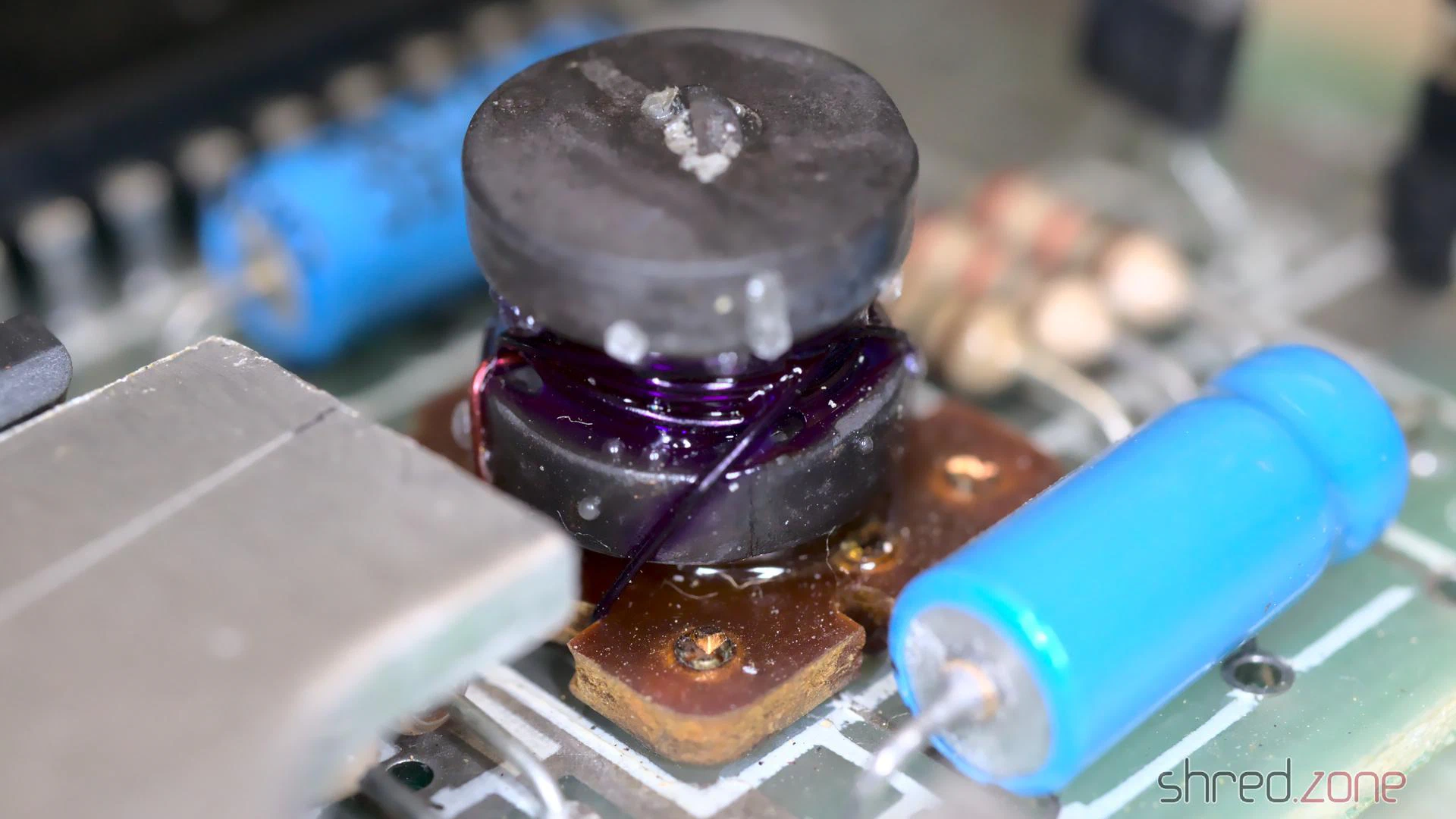
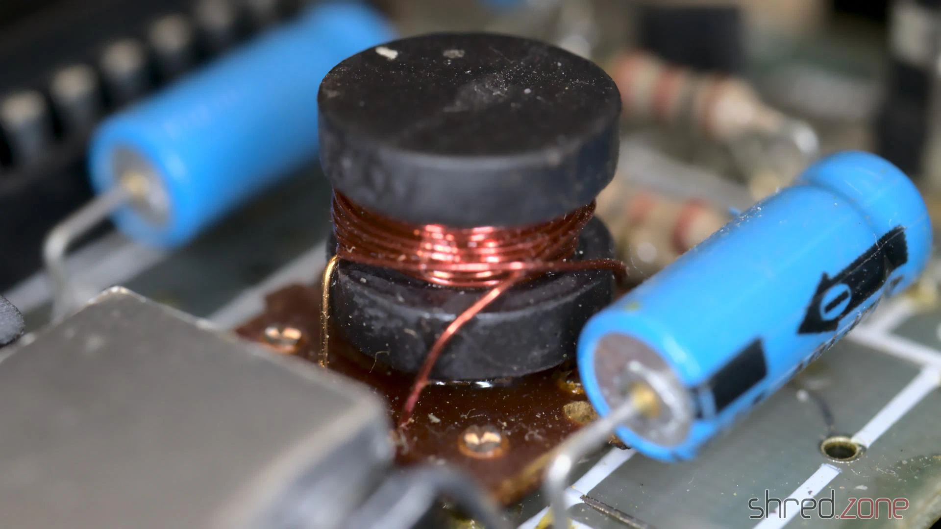
That kind of damage usually happens when an expansion cartridge is removed while the ZX Spectrum is still powered, causing a short circuit on the power lines. This poor computer must have given one last smoke signal before its decease.
The coil was custom made for the Spectrum. One can still get remakes today, but they are quite expensive. So why not just wind a new one myself?
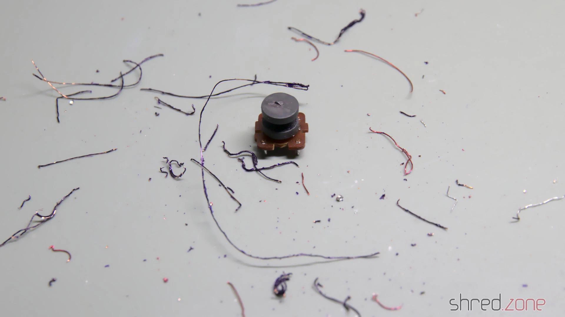
First I thoroughly removed all the old copper wire and the charred insulator plastics. I was hoping that I could just unwind the old coils and count the number of windings, but the insulation was melted to a single lump of plastic. The wire eventually tore, and I had to use a cutter to get the remains off the ferrite core. When I was done, it looked like the coil just exploded on my desk.
Luckily, the circuit diagram gives us all the information we need to know.
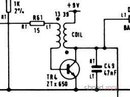
The original coil wire had a diameter of 28AWG (or 0.32mm), so we need insulated transformer copper wire of the same strength. For the inner coil we need about 30cm of wire, for the outer coil about 100cm.
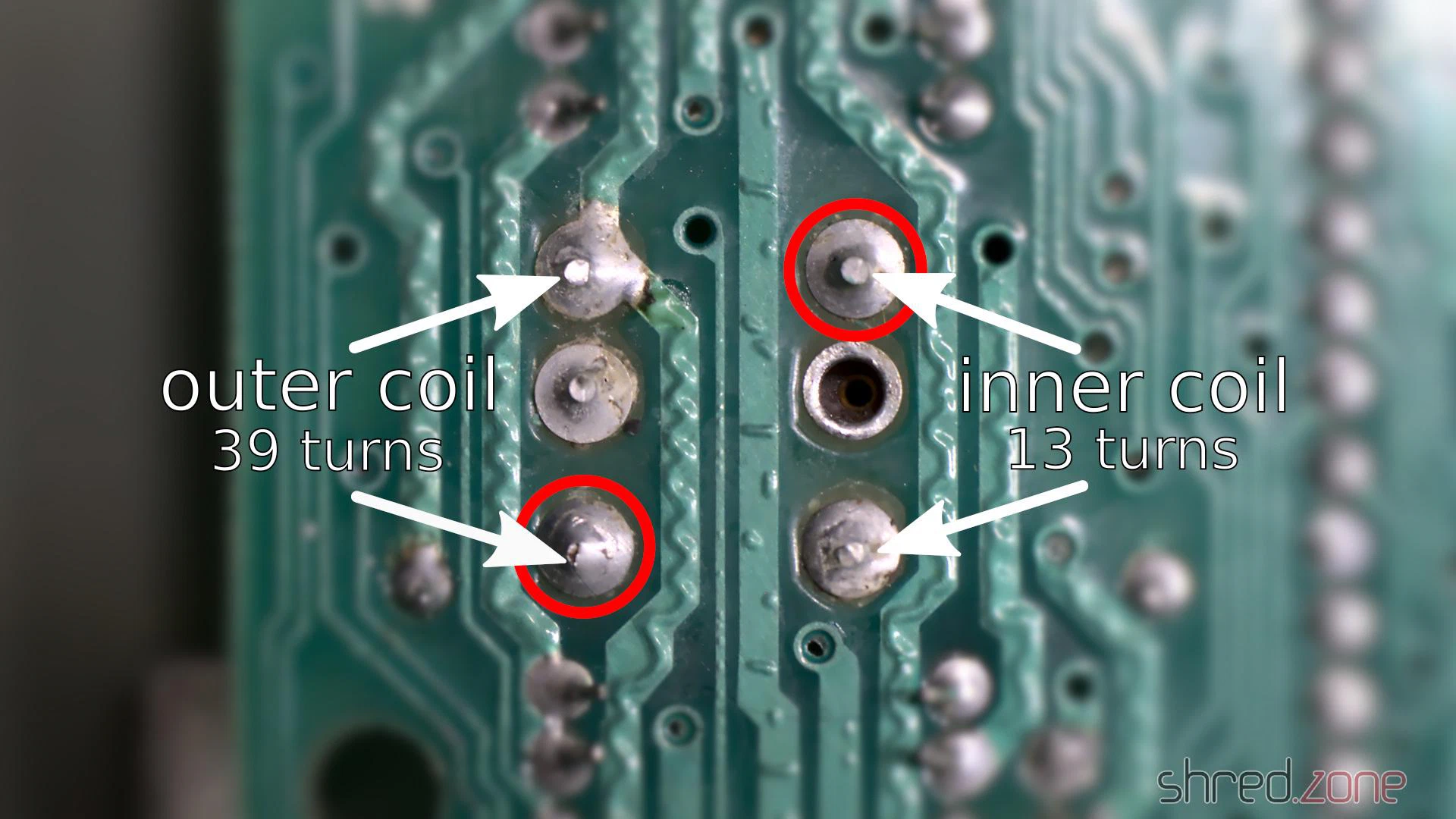
First we start with the inner coil. Wind a bit of the wire firmly around the pin marked in red on the next photo, then do 13 turns around the ferrite core, then wind the wire firmly to the other pin. The windings on the ferrite won’t need to be perfect, but should still be as tight as possible. I recommend to rewind the inner coil even if it appears to be intact, as the insulation might already be damaged.
After that, we do the same with the outer coil, having 39 turns. It is important that both coils are wound in the same direction. It doesn’t matter whether both coils are wound clockwise or counter-clockwise, as long as you use the same direction for both coils. The original coils are wound counter-clockwise when looked from above.
Finally, use a lighter to remove the insulation on all four pins, then use flux and a bit of solder to fix the wire ends to the pins. Now check with a multimeter. Both the primary and secondary coil should have less than 1Ω, but there should be no resistance between both coils.
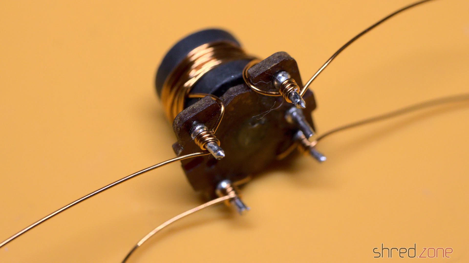
Now the coil can be soldered to the board again. The fifth pin serves as a key for the correct orientation.
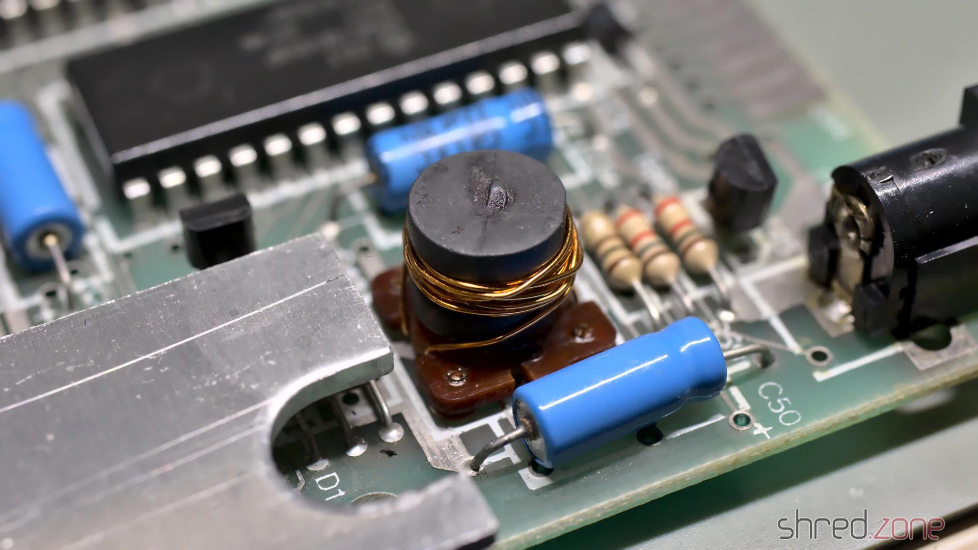
A shortened coil always causes secondary damage, so I preemptively replaced the components that usually fail as well:
- TR4: It can (and should) be replaced with a ZTX651, which is stronger and more reliable. They can still be found at good electronic retailers. I was researching for a standard transistor as replacement, but even though there were some types, the ZTX651 was always the strongest recommendation.
- TR5: The original type is not available any more, but can be replaced with a ZTX751 or a standard BC557 (which must be mounted facing in the opposite direction).
- D16: This can be any standard 5V1 Zener diode.
After that, I connected it to power, and (to my surprise, to be honest) all the three voltages were back and correct.
What’s Next?
The picture on the TV was still unchanged, but I had already expected that more components would be damaged.
I checked the temperatures of the ICs with my finger. If you try this at home, be very careful because a broken chip can get so hot it can easily burn your skin within a second.
The ULA got warm, but that’s normal. The CPU also got a bit warm, which wouldn’t be a surprise on modern computers, but the Z80A is supposed to stay cold. I unsoldered it, and replaced it with a 40 pin socket and a used SGS Z80A CPU that I once recovered from a broken ZX-81.
I powered it up again, and it just worked! 🎉
So there was just a burnt coil and a broken CPU. This repair was much easier than I had expected.
Finishing Works
Like on my other ZX Spectrum, I first replaced all the old electrolytic capacitors. I also used a fresh 7805 voltage regulator, and thermal paste for better cooling.
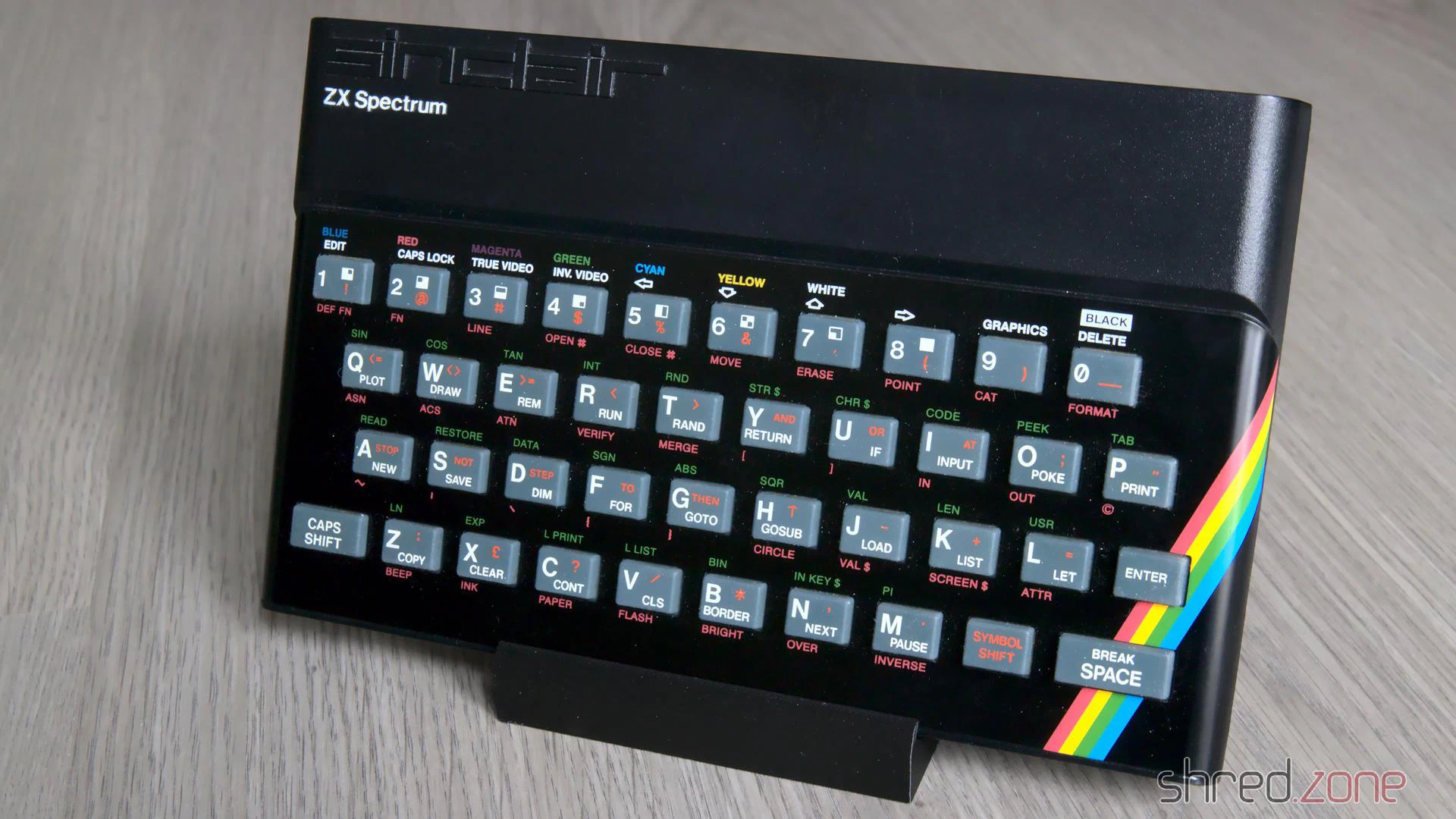
My first Spectrum got a transparent case and a chrome faceplate. For this ZX Spectrum I decided to keep the original look, so I just replaced the broken keyboard membrane. The old faceplace had some visible dents and scratches, so it was replaced as well. I then washed the original case in warm water with a bit of dish detergent, and then put it all back together.
And that is the story of the two sisters who got a nice makeover, and are now fit for the next 30 years. 🙂
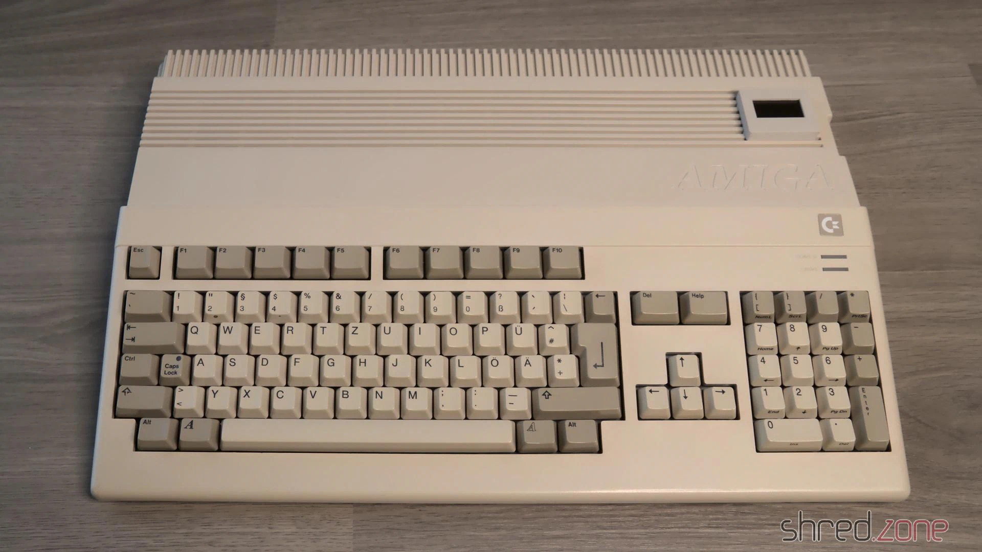
After the test run was successful in the previous part, it’s now time to put my Amiga back together.
Whitening
I’ve got the case parts and keycaps back from whitening at the CBM Museum Wuppertal. And the mandatory before-after photos proove that they did a great job:
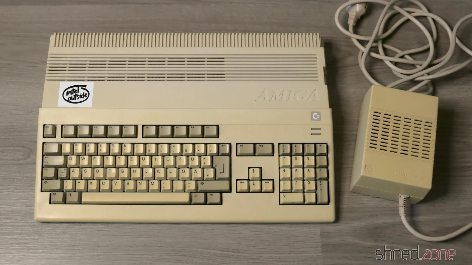
Sadly the PSU case is made of a cheaper material, and could not be whitened any further without risking the dreadened “marbling”, so it stills look a bit yellowed. (I forgot to use a ring light for the photos, but I did my best to make both pictures comparable.)
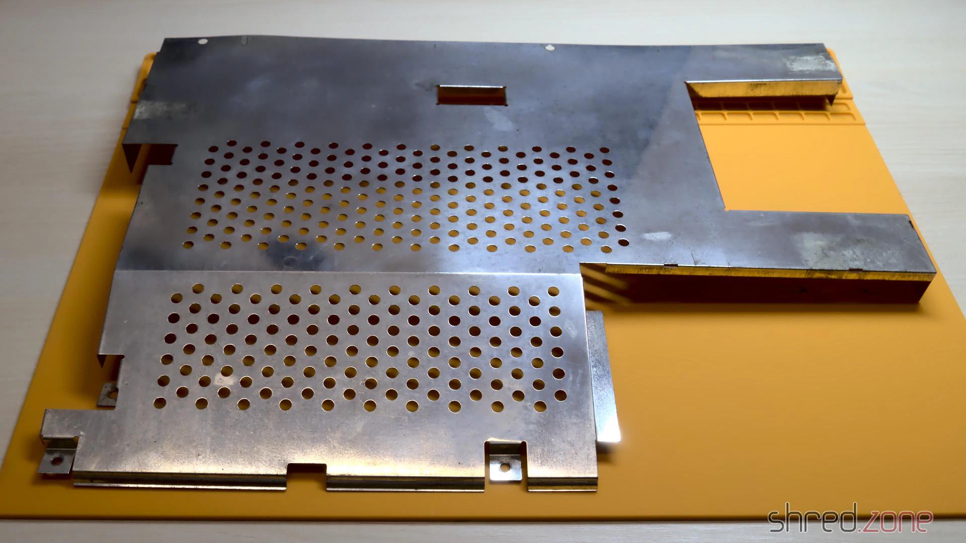
Removing the Rust
Due to my careless storage in the cellar, the metal shielding got a bit of rust over the years. I removed the worst rust spots with a fiberglass pen. Then I polished the shields with Nevr-Dull wadding polish, which removed a lot of the rust film. The result is still far from perfect, but it’s hard to impossible to restore the original look of the shielding, so I decided to keep it that way.
PSU
I have already prepared the PSU in in the last part. Now that I also got the PSU case back, it’s time to put it together. I’ve first replaced the power switch, as the old one got broken over the years. Luckily it’s a standard switch that can still be found at electronic shops.
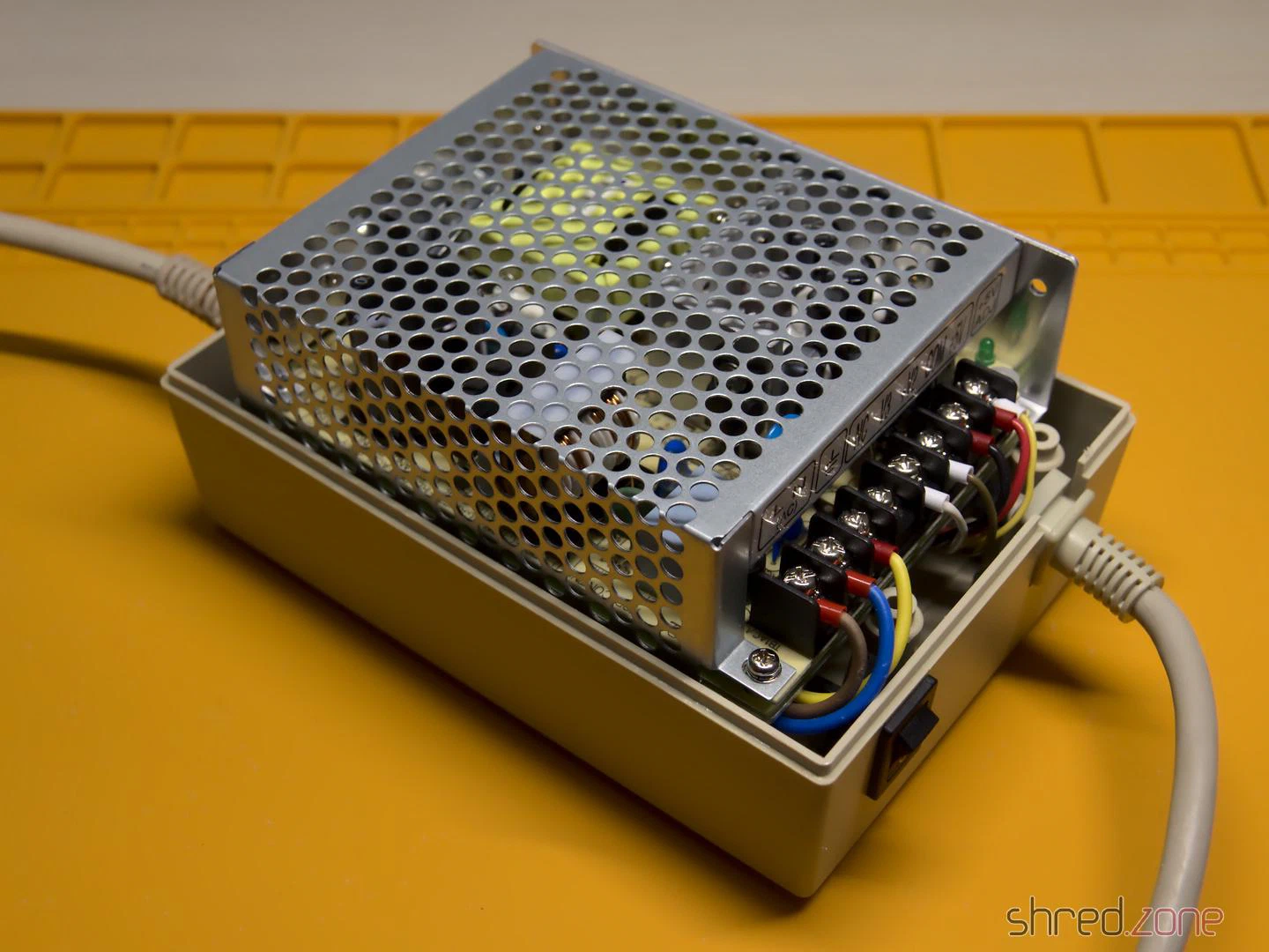
The Mean Well RT-65B fits into the case surprisingly well, almost as if it was made for it. I only had some difficulties to find a proper position for the wires. I tried different positions, and also tried to switch the sides of the mains and Amiga power cables.
The best result seems to be the original orientation of the cables (mains cable at the side of the power switch). With a bit of tweaking, I could finally route all the wires properly, make the RT-65B fit in, and close the PSU case.
I recommend to check the correct wiring (especially of the earthing) and the voltages once again. Also make sure that the terminals are firmly closed, and that no wires are overly bent, squeezed, or punctured.
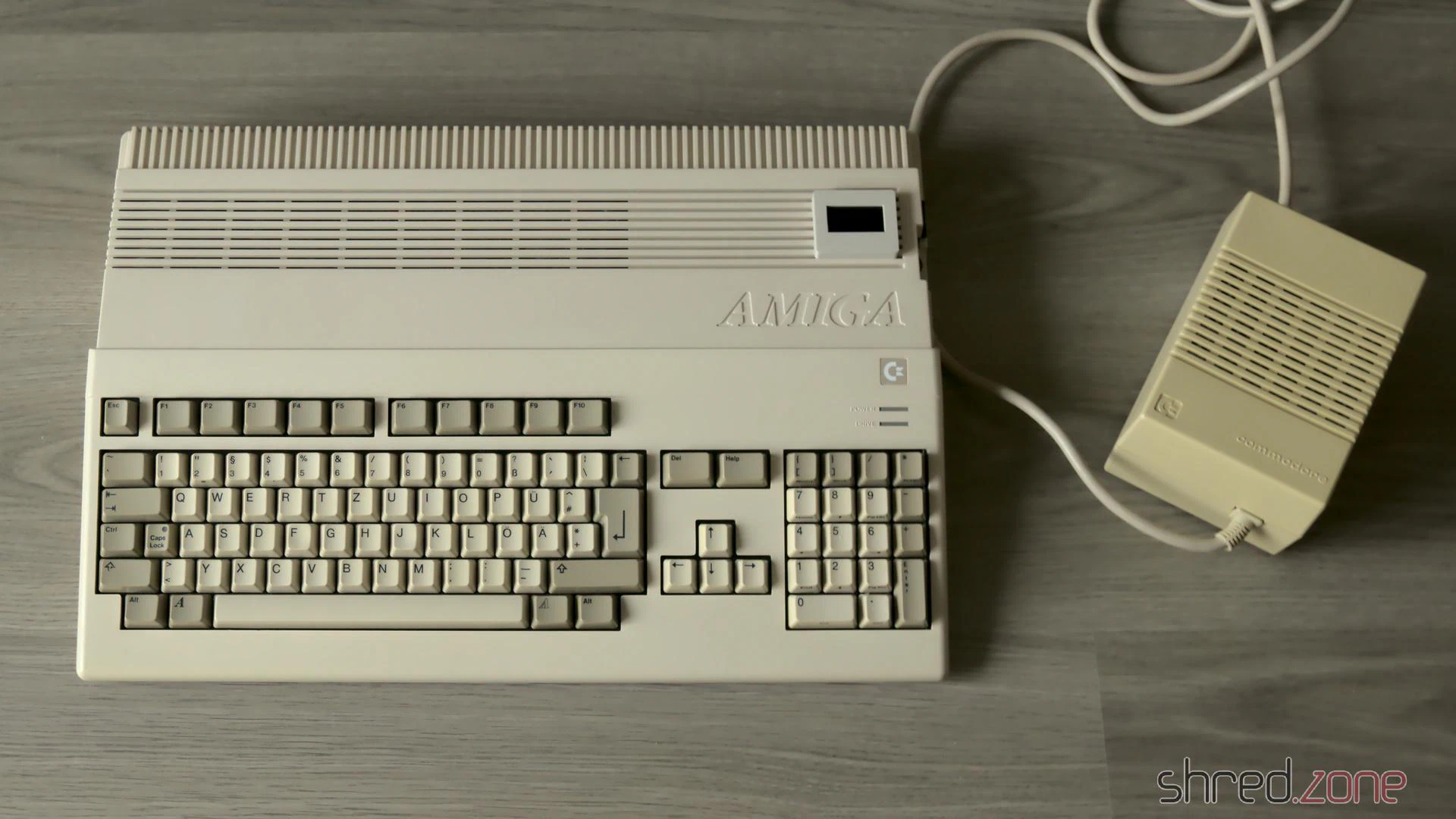
GOEX Drive
The GOEX drive optionally comes with an OLED display that sits on top of the Amiga case and shows the currently selected file, and the current disk track. I can really recommend to order that display with the drive, as it makes selecting a file a lot easier. Unless of course you use the “GOEX on pills” version that offers a disk menu on the screen as OSD, but I wasn’t sure how this version would interfere with the RGB-to-HDMI converter I am using.
The display is readily assembled, and already has crimp connectors at the end of the cable. The idea was to push them through an opening of the ventilation grille, but they just were too big for that. I had to cut them off, push the ribbon cable through an opening, and then solder new connectors to the cable.
HDMI Connector
Next problem was the HDMI connector. I use c0pperdragon’s RGB-to-HDMI converter to connect my Amiga to a TV or monitor via HDMI. But where should I put the HDMI connector so I can reach it from the outside of the case?
My original idea was to cut a matching hole into the back of the Amiga case, but later I dismissed the plan and decided against disfiguring the case even further than I already did in the 1990s. A better idea was to print an expansion port cover with a hole for a HDMI cable, even though I disliked the thought that a cable would then loosely hang out of the case.
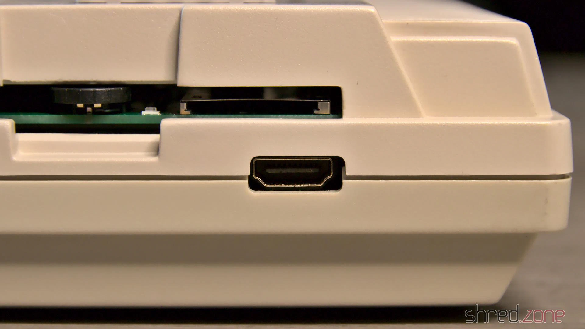
Then I noticed that the GOEX drive left a hole where the floppy drive’s eject button has once been. And this hole is actually big enough for a HDMI connector, almost as if it has always been meant for that purpose.
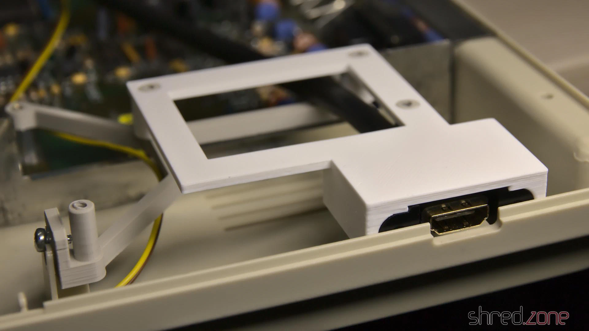
I designed a 3D printed frame that holds the connector of a Delock 85463 panel-mount HDMI connector. You can find the STL file at Printables for reprinting.
It looks a bit weird when a HDMI cable is plugged into that place where once the disk eject button has been, but it is working amazingly well, and saved me from cutting further holes into the Amiga case.
Completed
Now everything was mounted in its place. I couldn’t close the upper shielding though, because the HDMI converter is in the way, so I decided to leave it out.
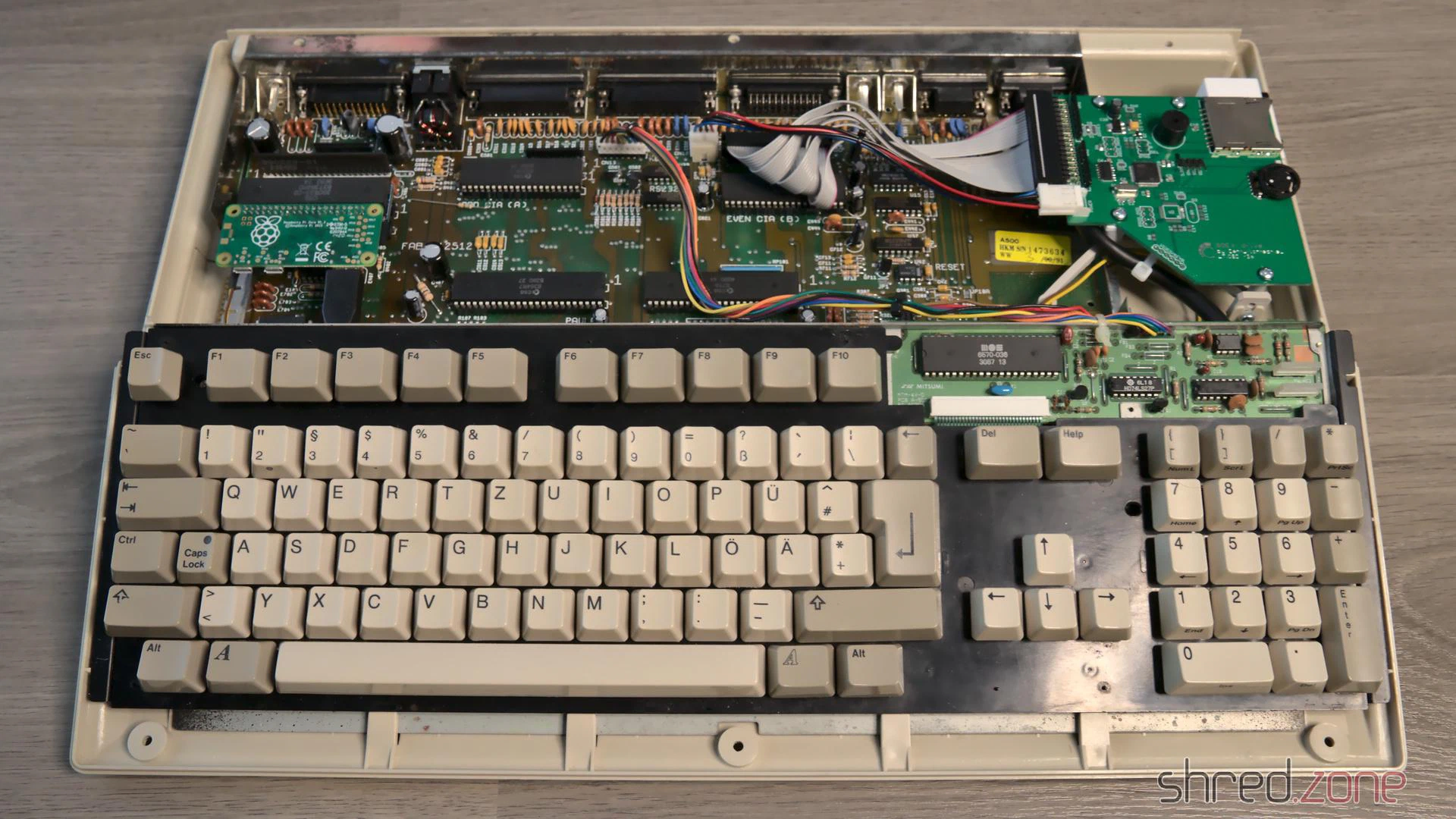
And that concludes the restauration project. Welcome back, Amiga 500. With this hardware upgrade, you should be fit for at least the next decade.
The Kickstart Dilemma
Well, not quite. There is a Kickstart 2.04 ROM installed in this Amiga, and while playing some old games, I found out that a surprisingly large number of them crash on that version of the AmigaOS. It was indeed a big problem of the Amiga back in these days. In the previous generation of home computers, the operating system was static and was never updated, so programmers assumed to find certain routines at fixed positions. When the Amiga got popular, programmers continued to use the operating system like that, ignoring documented rules. Then in 1990, Commodore released Kickstart 2.0, a major AmigaOS upgrade. And suddenly, many poorly programmed games crashed, but instead of the programmers, the Amiga was blamed for it.
I still have an original Kickstart 1.3 ROM here, along with a ROM switch. Maybe I will use that board again. Luckily, I haven’t yet closed the holes that I once drilled into the case, so I can use one for the switch again.
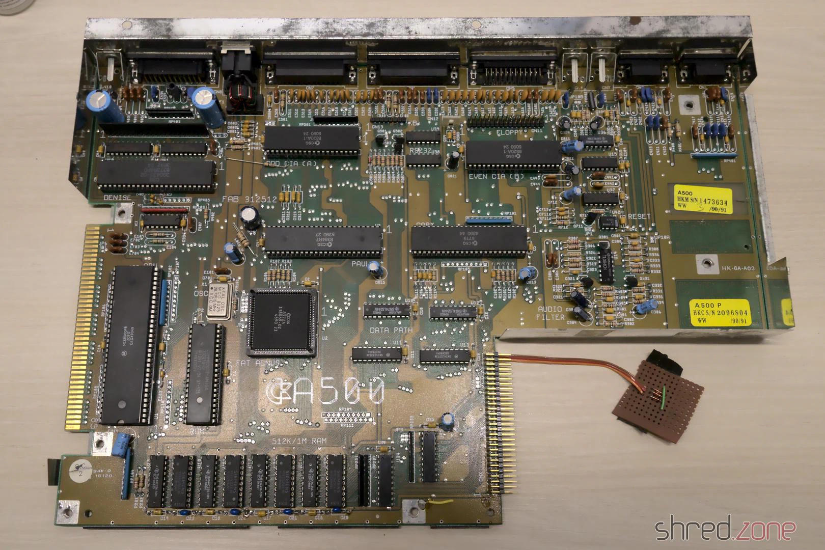
In the first part, I dusted off and checked my old Amiga 500. I’ve also ordered all parts for the project, and they have been delivered by now. Let’s start with the restauration!
Recapping
All home computers of the 1980s and 1990s have been designed for common households, and thus had to be cheap. Commodore did not expect that the Amiga would become an “old dame” some day, so they used standard components. A common problem is that electrolyic capacitors dry out over the years, losing their capacity. Some may even leak and, in worst case, damage the board. So the first restauration step is always to replace all electrolytic capacitors, even if they should still look fine.
As I don’t want to repeat that process in a decade or so, I ordered premium capacitors with an expected lifetime of 10,000 h, which is probably tenfold of the standard caps’ lifetime. At the bottom of this article, I have listed all the caps on my Amiga 500 Rev 6A board.
On the first sight, all capacitors seemed to be fine. Still, after removing one of them, I found traces of dried electrolyte on the board and at the bottom of the component. It really shows that a superficial inspection can be deceiving.
I also removed the wires of my self-made NMI button, and looked for cold solder joints and other potential problems. As final step, I carefully washed the mainboard with IPA.
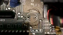
HDMI Output
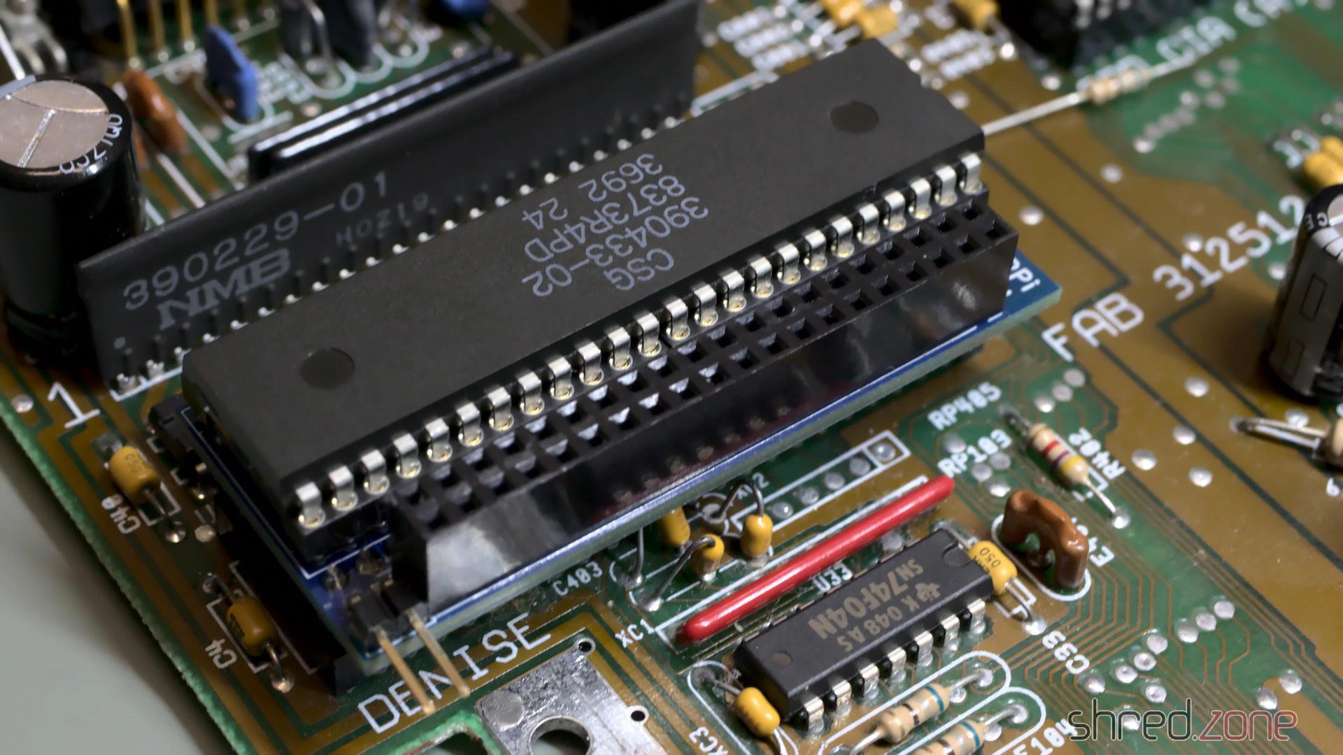
Let’s start with the next construction site. As it gets more and more difficult to find TVs with a SCART connector (and I never liked them anyway), I want to connect my Amiga 500 via HDMI. Luckily there is a project by c0pperdragon that adds a pixel-perfect HDMI output to the Denise chip. The converter cannot be bought at shops, but you need to assemble it yourself. It consists of a few standard components that can be bought at good electronic shops, while the board can be ordered at PCB manufacturers. The assembly requires some fine-pitch SMD soldering though. If you don’t feel comfortable with that, you maybe find a private seller for a readily assembled board.
To install the adapter, the Denise chip is removed from its socket first. Then the adapter is placed into the socket, and Denise into the adapter. A button can be connected for changing the configuration and taking screenshots, but that is not really required for operation.
The RGBtoHDMI firmware needs to be extracted to a FAT formatted MicroSD card. Make sure to use release 20210322_f771e51 or later. Earlier releases will not work, but only show four colored rectangles.
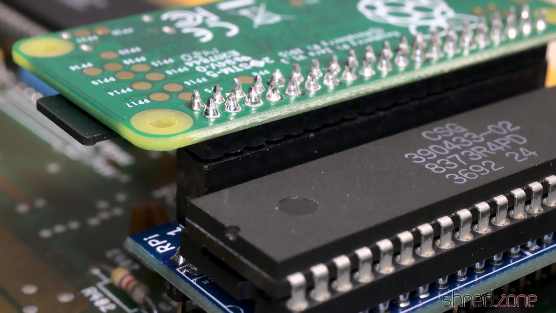
Finally the Raspberry Pi Zero is plugged into the socket. Be very careful here! The pin header will also fit if not aligned properly, and may then damage your Raspberry or (even worse!) your Amiga.
New Power Supply
In the first part I found some liquid at the bottom of the power supply’s PCB. I suspected it was capacitor liquid, but my contact at the CBM Museum Wuppertal explained me that it was just a lot of flux. Still, the old power supply would need a technical overhaul, which I can only recommend to people who know exactly what they are doing.
WARNING: Switched power supplies may still contain high voltages hours after they have been disconnected from mains. I strongly advise against attempting repairs yourself. If you decide to keep your old PSU, please ask a trained technician to restore it for you!
As I am not “trained personnel” myself, I decided against restoring the original PSU, but for replacing it by a Mean Well RT-65B. It has sufficient power, and also fits nicely into the original Amiga PSU case.
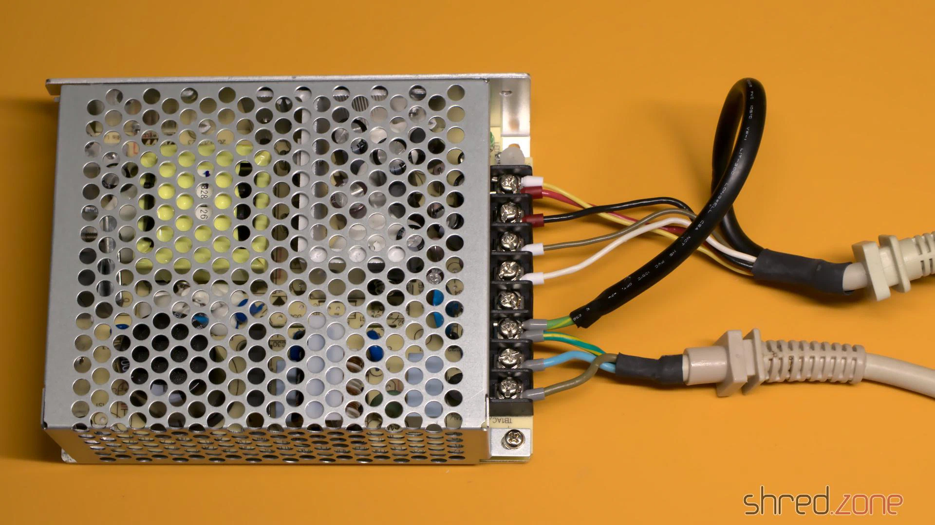
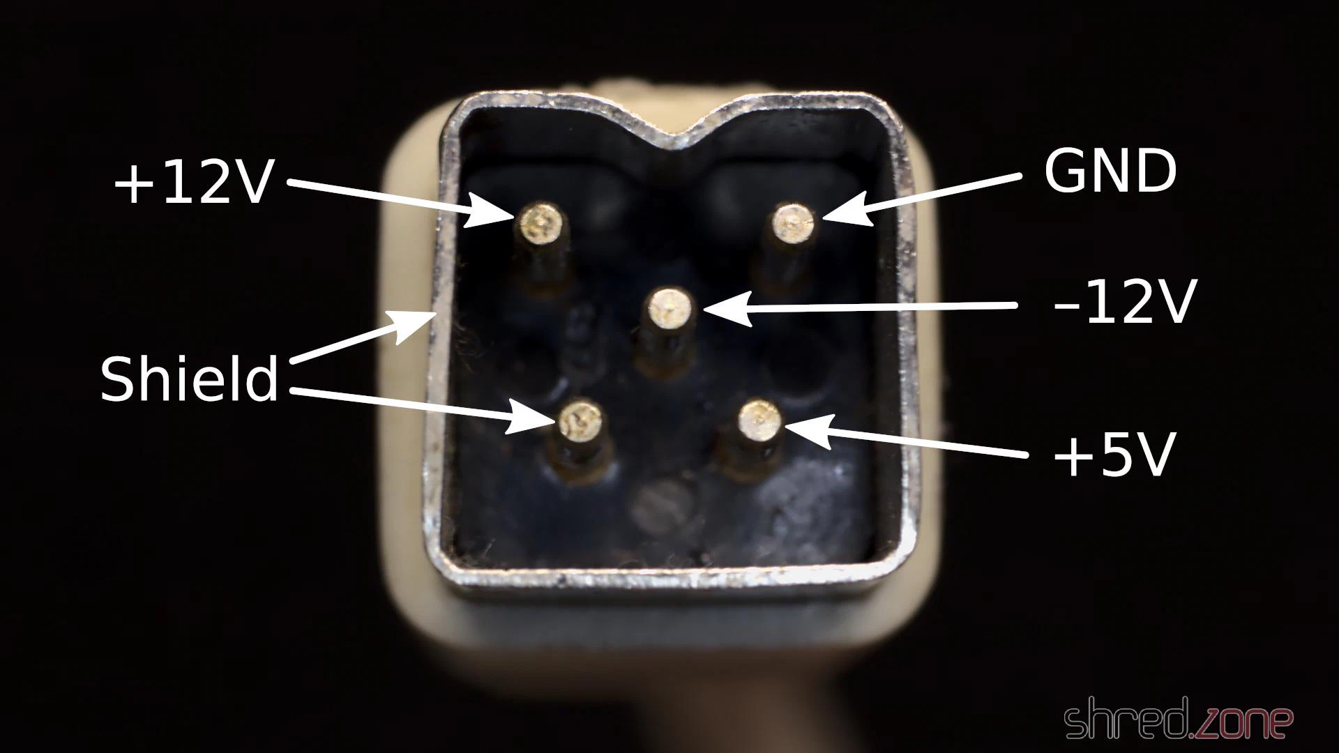
Before I removed the wires from the old PSU, I took notes on what color is connected to what voltage. Then I removed the wires, put crimp shoes on the wire endings, and connected them to the corresponding output of the new PSU.
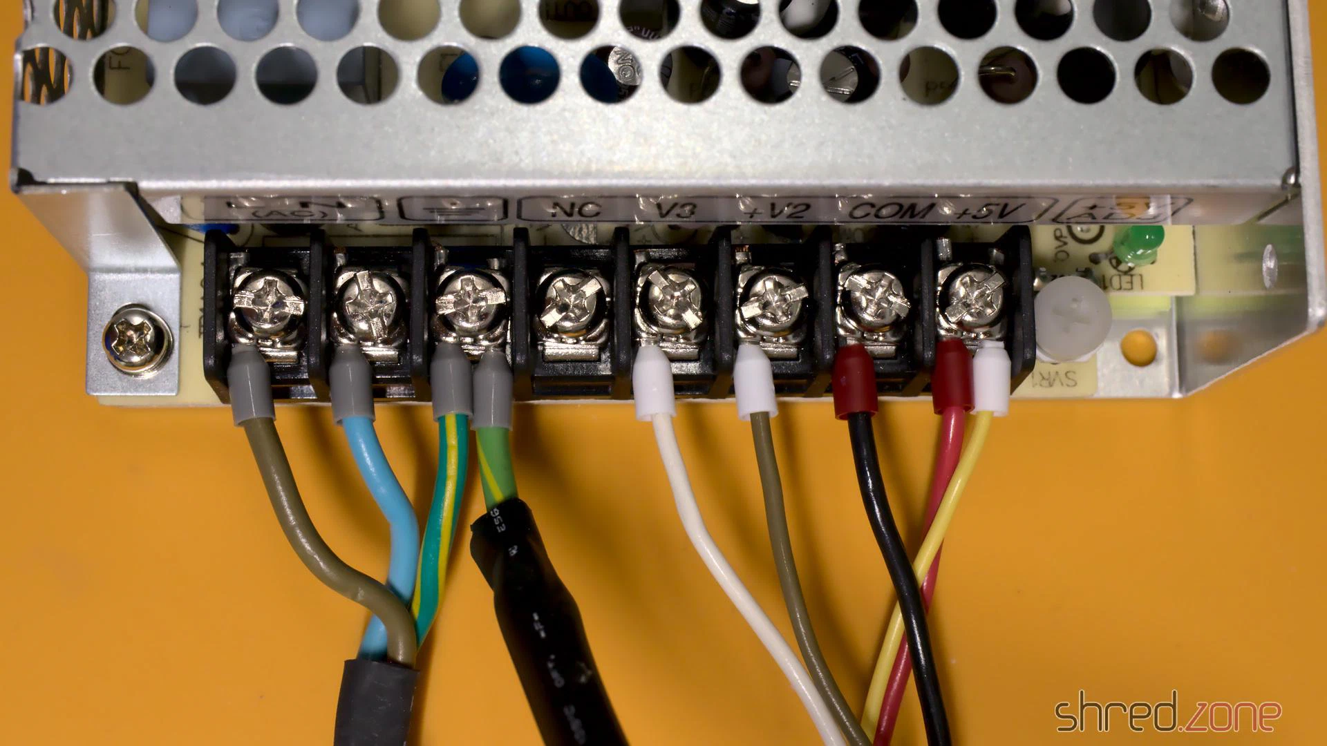
My original PSU had a separate SEN wire. It is connected to +5V at the power plug, and is used so the old PSU could compensate wire losses and provide exactly 5V there. The replacement PSU does not provide a sense connector, so I just connected the SEN wire to the +5V line to increase the total cross-section and reduce losses, but it can also just be left open.
The “shield” wire must be connected to earth.
ATTENTION: There were different variants of Amiga 500 power supplies on the market. Your number of wires, and the wire color code, may be different. Do not just rely on my photos!
This is how it looked like after the wiring:
Do not connect your PSU to mains yet! First switch your multimeter to continuity test mode, and test if your earthing is connected to the PSU case, and to the shield and the shield pin of the Amiga power plug. After that, test if the power lines are properly connected. Now you can power up your PSU, and use your multimeter to check the voltages at the Amiga power plug.
ATTENTION: Please be very careful when you test the PSU outside the case. Make sure you cannot accidentally touch the live terminals. Also do not open the shielding of the PSU.
Test Run
After I made sure all voltages are correct, it was finally time for a first test run.
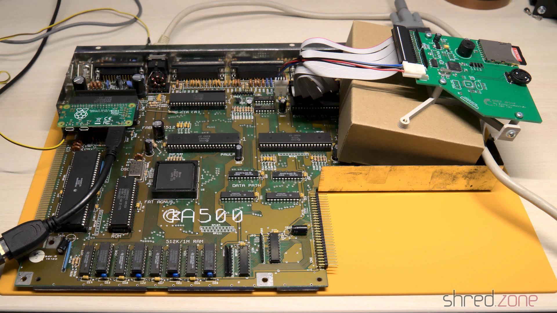
As I don’t have many disks any more, I had ordered a GOEX drive as a replacement for the original floppy drive. It emulates a disk drive, but uses ADF files from a SD card. It even emulates the mechanical noises of the head stepper motor, which actually sounds much better than expected. I connected it to the floppy header of the mainboard, and used a cardboard box to make sure it won’t cause short circuits.
Then I checked everything again. Is the mainboard okay? Is the HDMI converter properly connected? Is the GOEX drive connected? Is the Raspberry properly seated and the MicroSD inserted? Is nothing there that might cause a short circuit? Is the PSU protected against accidental touching the live terminators?
And then, after almost 30 years, it was finally time to wake up my Amiga 500 again.
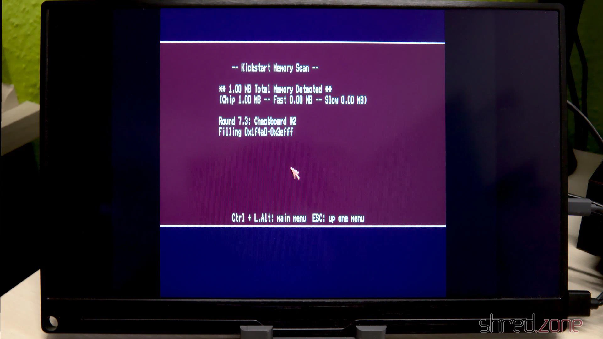
I first booted an Amiga Test Kit disk and checked the RAM and the CIAs. After that, I ran some demos. The picture quality of the HDMI converter is stunning!
Meanwhile I also got the case and keyboard back from the whitening service. I cannot wait to put it all back together, and enjoy my shiny new Amiga 500.
Capacitor List
The caps list of my Amiga 500 Rev 6A, and the replacement parts I used:
| Qty | Type | Reference | Manufacturer Number |
|---|---|---|---|
| 2 | 3300µF 10V | C401 C402 | Panasonic EEU-FR1A332 |
| 1 | 470µF 16V | C307 | Panasonic EEU-EB1E471 |
| 6 | 100µF 16V | C811 - C816 | Panasonic EEU-FR1E101B |
| 2 | 47µF 16V | C821 C822 | Panasonic EEU-FR1H470B |
| 4 | 22µF 35V | C303 C304 C324 C334 | Panasonic EEU-FR1H220 |
| 2 | 10µF 35V | C306 C712 | Panasonic EEU-FR1H100B |
Notes:
- All capacitors are radial and have a lead spacing of 5mm.
- C401, C402: Height should be 24mm or less to fit under the shielding.
- C324, C334: Bipolar caps may enhance audio quality. I haven’t tested that though.
- You can use any fitting capacitors with the same capacity and the same (or higher) voltage.
- Temperature rating should be 85°C or, even better, 105°C.
A few years after I got my Amiga 500, I bought an Amiga 4000 from the pay I got doing my civilian service. At its peak, it was housed in an RBM Big Tower case, and had all kind of expansion cards and an 68060 accelerator board. It was my pride and joy. Later, after Commodore went bankrupt, I switched to Linux systems. My Amiga 4000 was put on a diet and moved back into a desktop case.
The restored Amiga 500 is meant to be used for playing old games and watching demos. In contrast to that, the Amiga 4000 is supposed to become a workstation again. It should be connectable to modern monitors, and should be as silent as possible.
This is the state of the case before restauration.
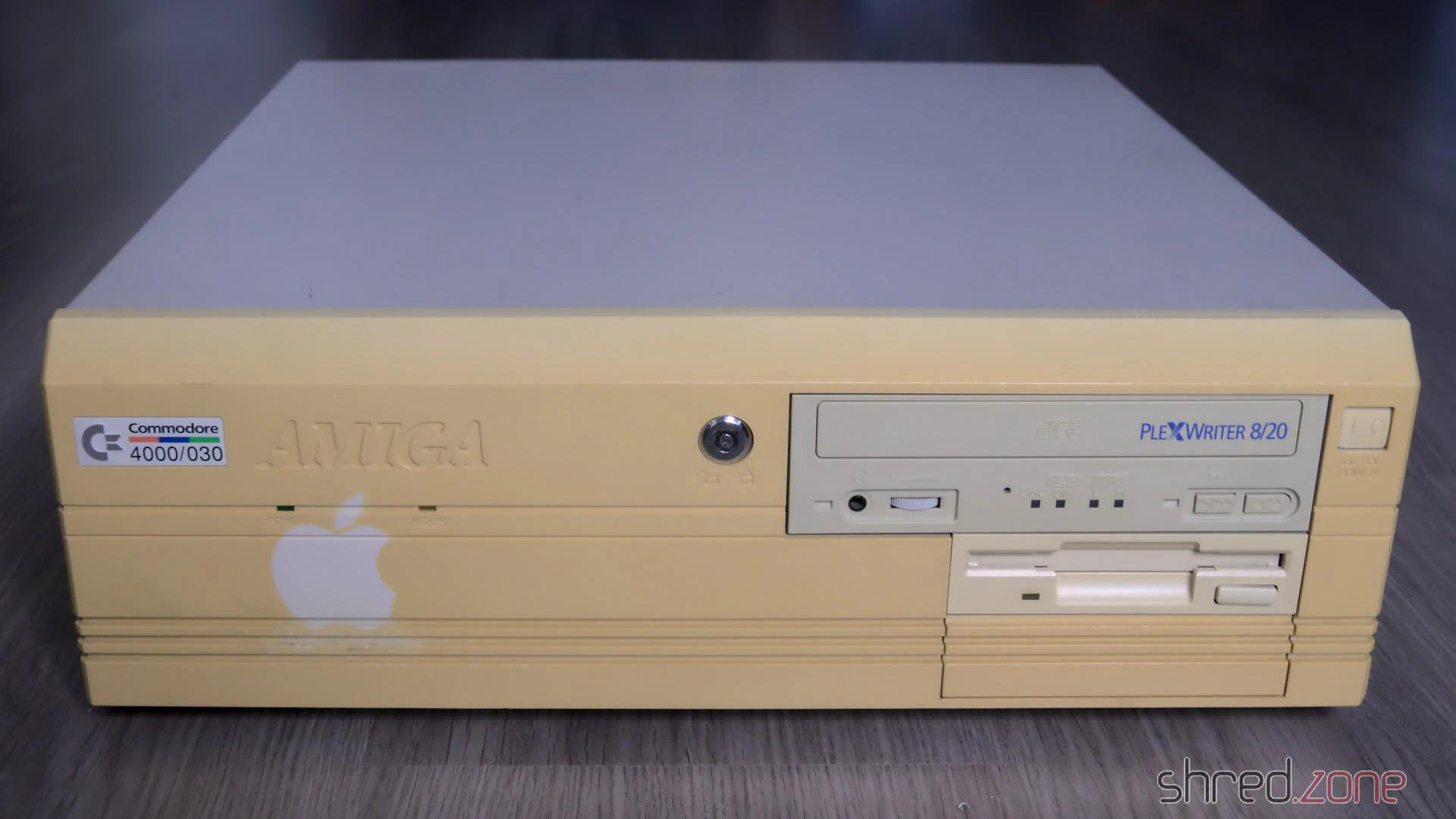
The computer has suffered a lot in the past decades. The powder coating of the metal cover got a lot of deep scratches from CRT monitors that were placed on it. The plastic front got a deeply yellowed tint. To make things worse, there was a sticker on the front that kept the plastic from yellowing, but now the outline is permanently “burned” into the front instead. The keyboard was in a similar state, although not that badly yellowed.
The CBM Museum Wuppertal already did an excellent job with whitening my Amiga 500, so I decided to also let them whiten the front panel and the keyboard. The experts at the museum warned me that the logo might stay visible after whitening though, but then I could still resort into dying the front black, or even 3D print a new front.
Meanwhile a paint shop is taking care for repainting the metal cover. I decided to keep the original color, RAL 7044 (silk grey).
Let’s have a look at the inside now.
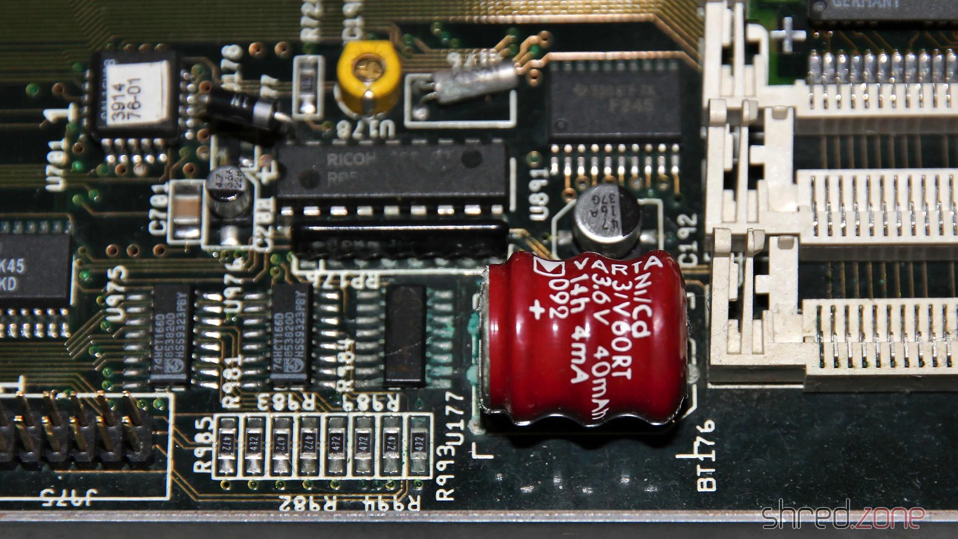
Leaked Battery
A true Amiga killer is the NiCd battery that serves as a power backup for the RTC. Sooner or later it leaks and spills battery lye onto the PCB. The lye corrodes the components and traces in its vicinity. If untreated, the board can become irreparably damaged over time. When I first heard about the problem eight years ago, I immediately cut out the battery, but sadly it had already leaked.
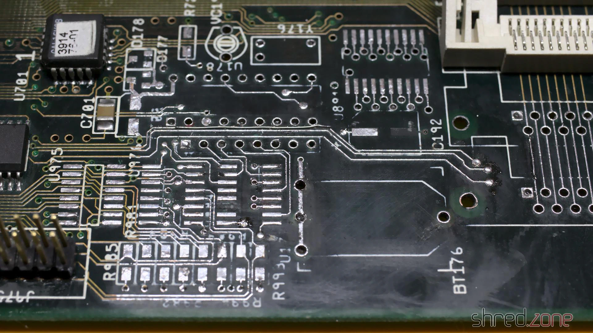
For the restauration, I needed to repair this part of the PCB. I generously removed all affected components. Then I neutralized the lye with vinegar essence, rinsed the area with water, then cleaned and dried it with IPA. After that, I used a fiberglass pen to remove the solder mask down to the bare copper, to have an unobstructed look at the damage.
I lost two pads that seemed to be too damaged by the lye. They just came off while I was cleaning the board. Luckily one of them was not connected, and the other one could be replaced with a short piece of wire.
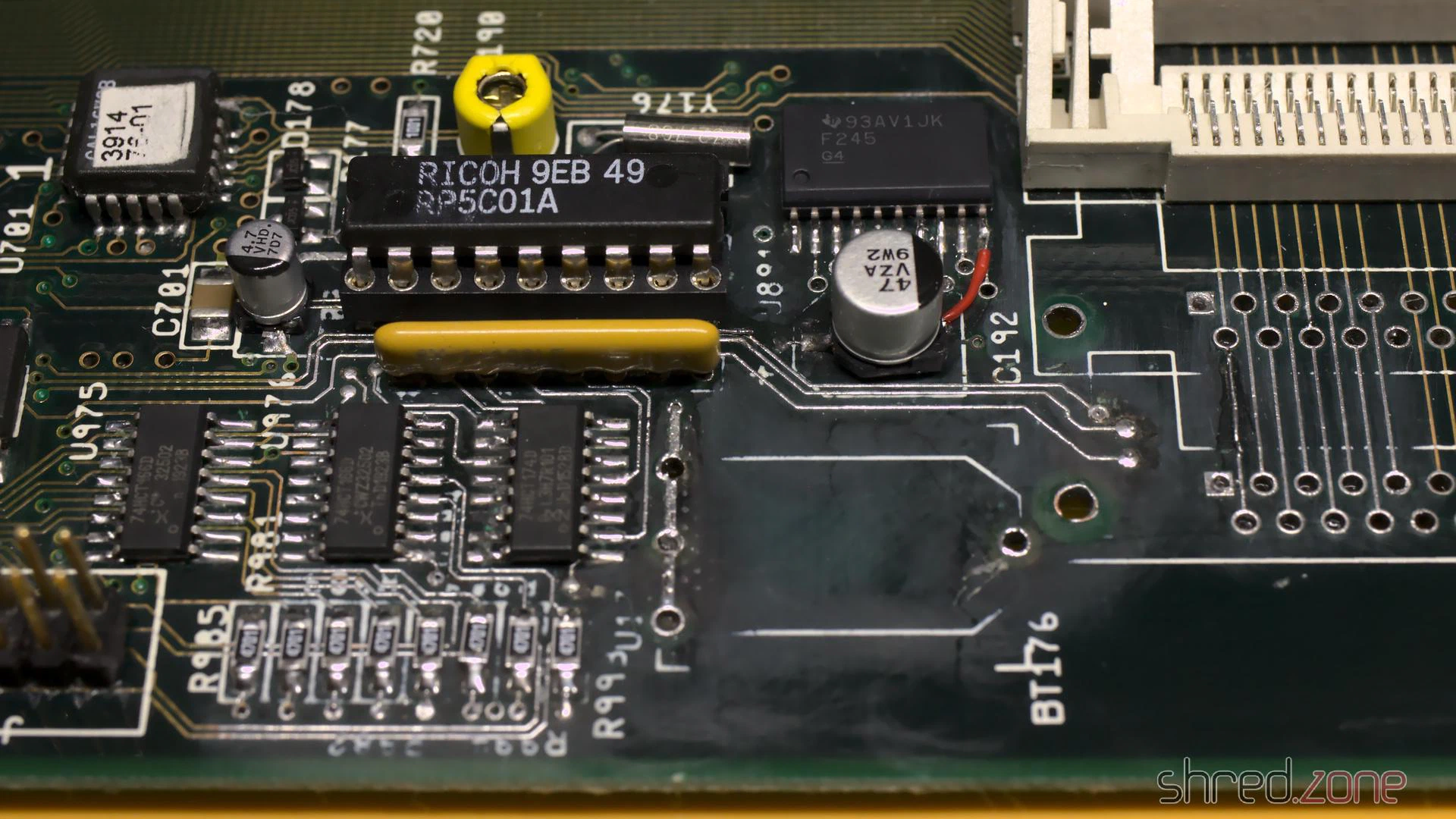
After that I rang all the traces. Three of them were open and also needed to be fixed with a piece of wire. I then used solder to tin the bare copper traces and protect them from corrosion. Finally, I soldered in fresh components.
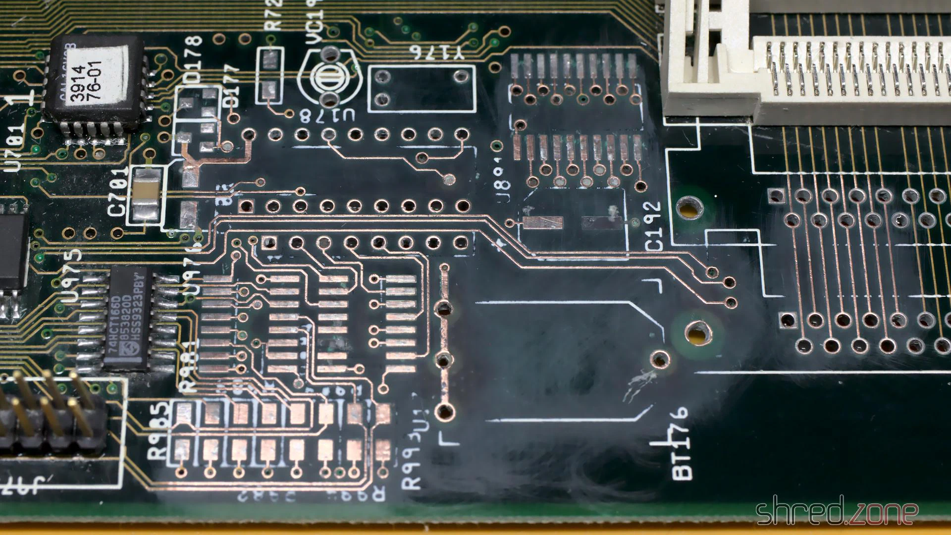
The lye may run to the bottom side through the vias, so it should be checked as well, and repaired if necessary. Luckily I could see no damage on my board.
Since the old rechargeable battery almost killed my Amiga, I decided to use a 3V button cell for backing up the RTC. To prevent the cell from being charged when the power is turned on, I replaced R179 with a standard diode.
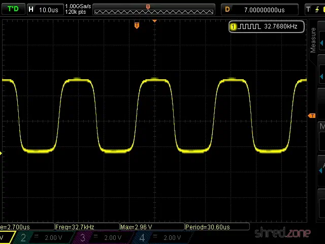
Since I removed the crystal and capacitors, the RTC needs a recalibration. I connected pin 17 of the RTC chip (U178) to a scope, and then used a plastic screwdriver to adjust VC190 until the measured frequency was exactly 32768 Hz.
Recapping
Electrolytic capacitors may leak, similar to the battery, and it is recommended to replace all of them with modern premium caps. Some people replace them with ceramic capacitors. They cannot leak, but may have other disadvantages. There are good arguments on both sides, so it’s a decision that everyone has to make themself. I decided to order the premium capacitors from my Amiga 4000D Bill of Material list. They are made by Panasonic and have an expected lifetime of up to 10,000 hours, which is maybe the tenfold of the original caps. They are also certified for temperatures of up to 105°C, which further extends lifetime.
There are different ways to remove the old electrolytic capacitors. The recommended way is to use two soldering irons, or a hot air rework station. I decided to use a different method that I read about, and twist them off with pincers. It worked surprisingly well, and it took only a few minutes to remove all the caps. To avoid causing damage to the pads, care must be taken that the caps are only slowly twisted, but not pulled from the board.
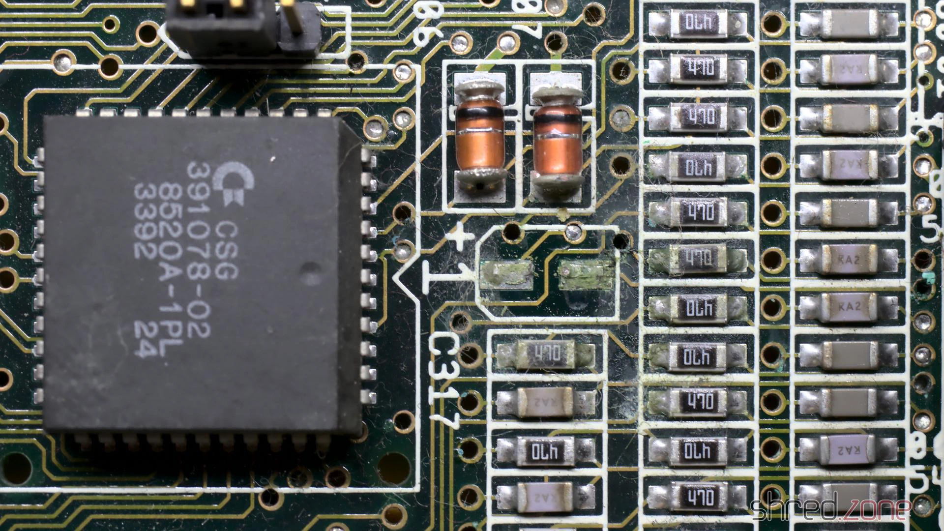
On the Amiga 4000 the leakage usually starts in the “audio corner”, where many SMD caps are concentrated on a small space. I was lucky because all the caps were still intact there. On my board, C317 has leaked though. It was visible by the corroded solder joints around it. When they were heated, there was also a typical telltale smell of microwaved fish. Again, I generously removed the components around the damaged part, cleaned the PCB, and soldered in new parts.
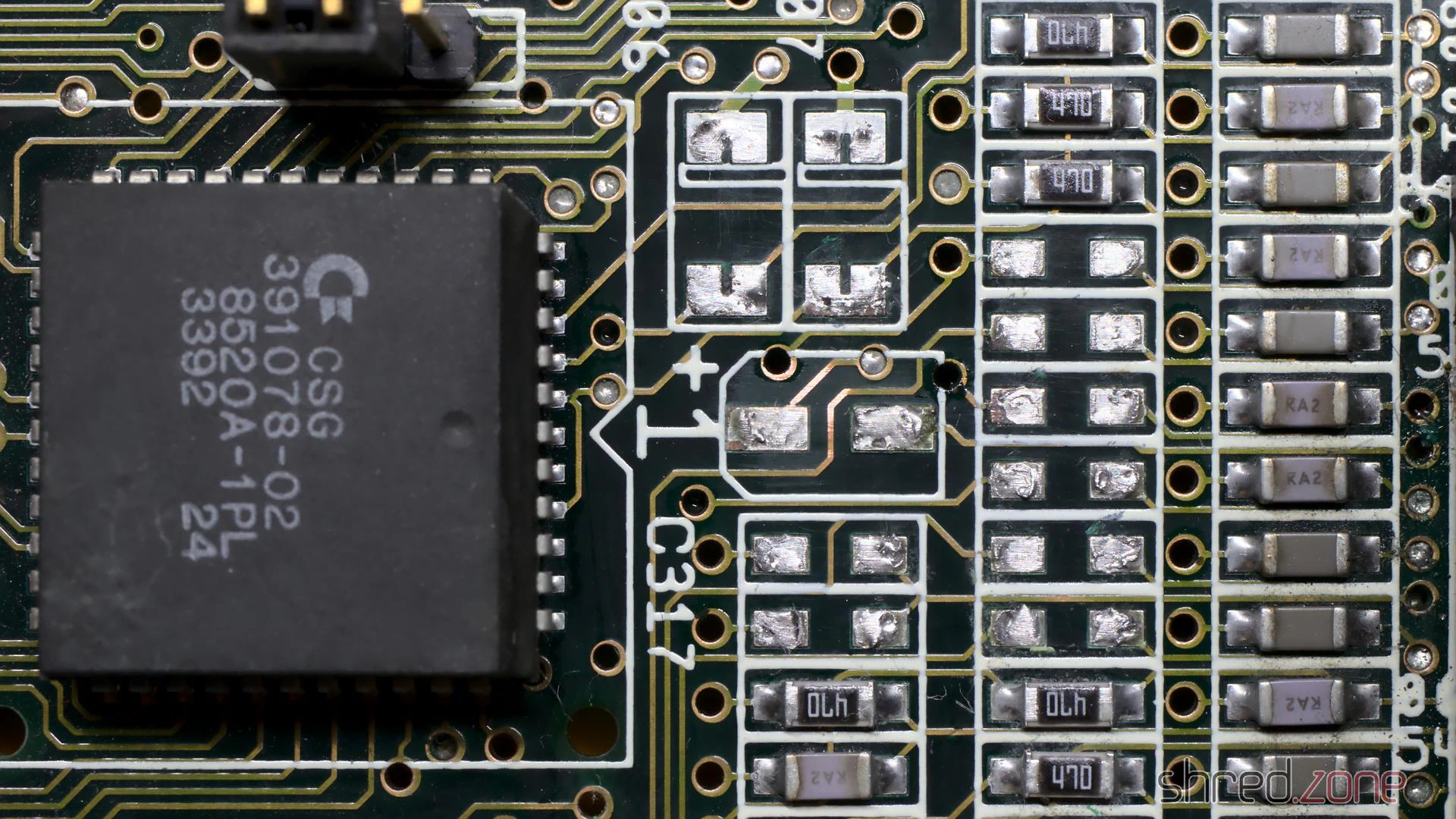
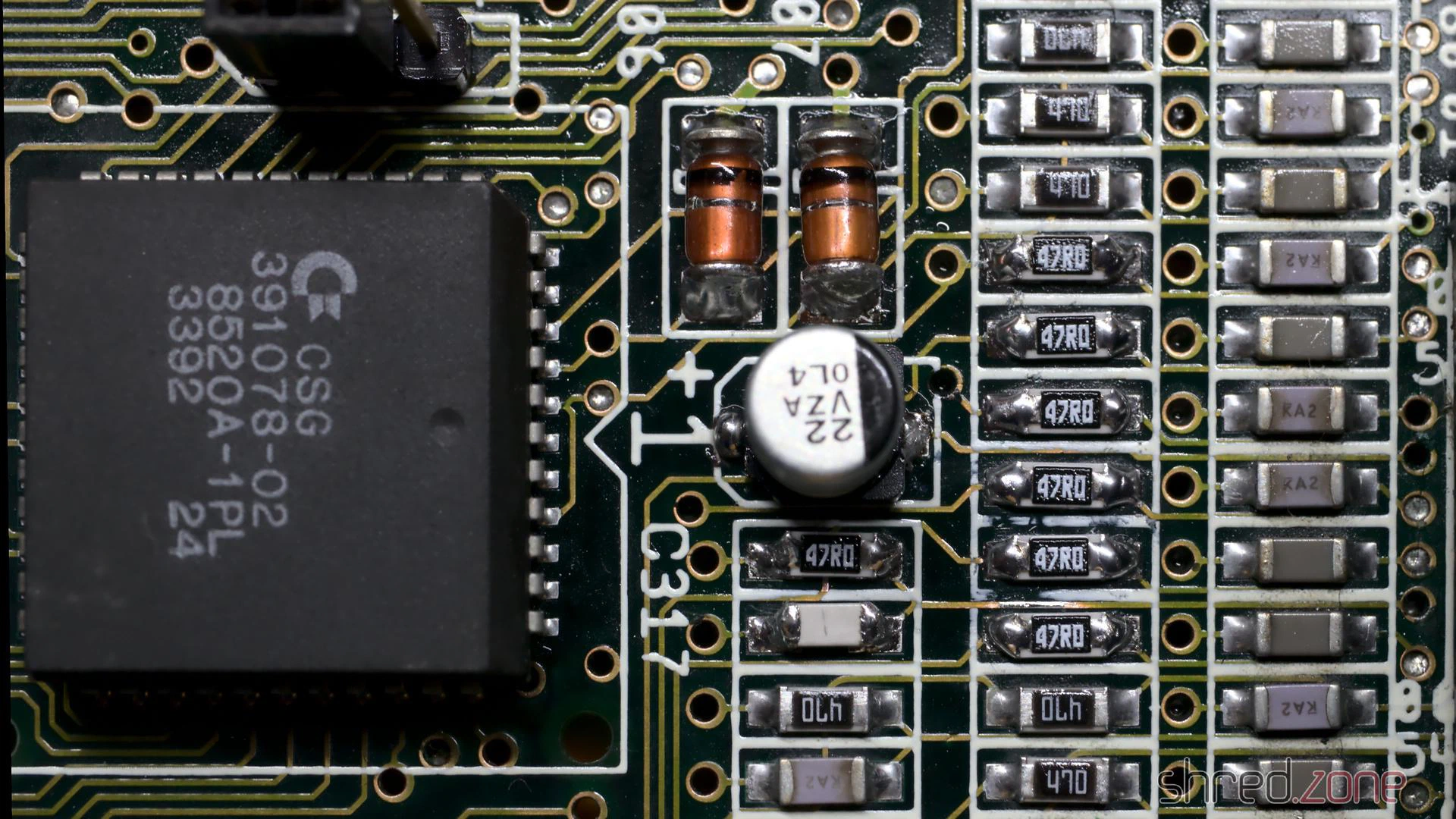
There are also a few axial caps on the daughterboard. They usually don’t tend to leak as easy as SMD caps, but since we’re on it, they should be replaced as well.
When I repared the battery damage, I also had to remove two of the SIMM sockets. The original sockets have plastic brackets that easily snap off, so I decided to finish what I started, and replaced all five sockets with new ones having metal brackets.
In a final step, I washed the board with IPA. It was then repaired, cleaned, and ready to be put back into the computer case.
In the next part I will take care of the power supply, and I will put the system back together.
My first Amiga was an Amiga 500. A classmate already had one, and when I visited him and saw the Amiga for the first time, I just had to have my own. So I pestered my parents until they gave in and bought one for me. With this computer I learned 68000 assembler, programming in general, and blind ten-finger typing.
A few years later, I bought an Amiga 4000 from the pay I got doing my civilian service. My good old Amiga 500 spent a few grace months in a closet, and was then stowed away in a box in the basement, forgotten for about three decades.
I would like to restore this machine, make it beautiful again, and give it a subtle technical overhaul. This project is a work in progress. I will report in my blog whenever there is something new. And in the end, I can hopefully share a feeling of success with you.
These are my goals for the restauration project:
- The case has likely got a yellow tint over the years, like all white computer cases of that era. The yellowing has to go, the case should look as good as new again.
- I will give it a technical overhaul. The electrolytic capacitors may have leaked and will be replaced. But after all the years, there may be even more technical problems that need to be fixed.
- Since I have almost no floppy disks left, the floppy drive will be replaced by a drive simulator.
- The old 1084 CRT monitor is long broken and disposed of (I hated these old flicker boxes anyway). I want to connect the Amiga to a modern TV instead, preferably via HDMI, so I will have a closer look at this Raspberry Pi Zero based converter that will be connected to the Denise socket.
After the restauration, the Amiga should feel (more or less) like it did when I once got it. This means that there will be no accelerator card or harddisk controller. Apart from the HDMI output and the floppy simulator, the only acceptable “tuning” is the chip RAM extension to 1 MByte.
Okay, so let’s get the computer out of the box and have a first look at it:
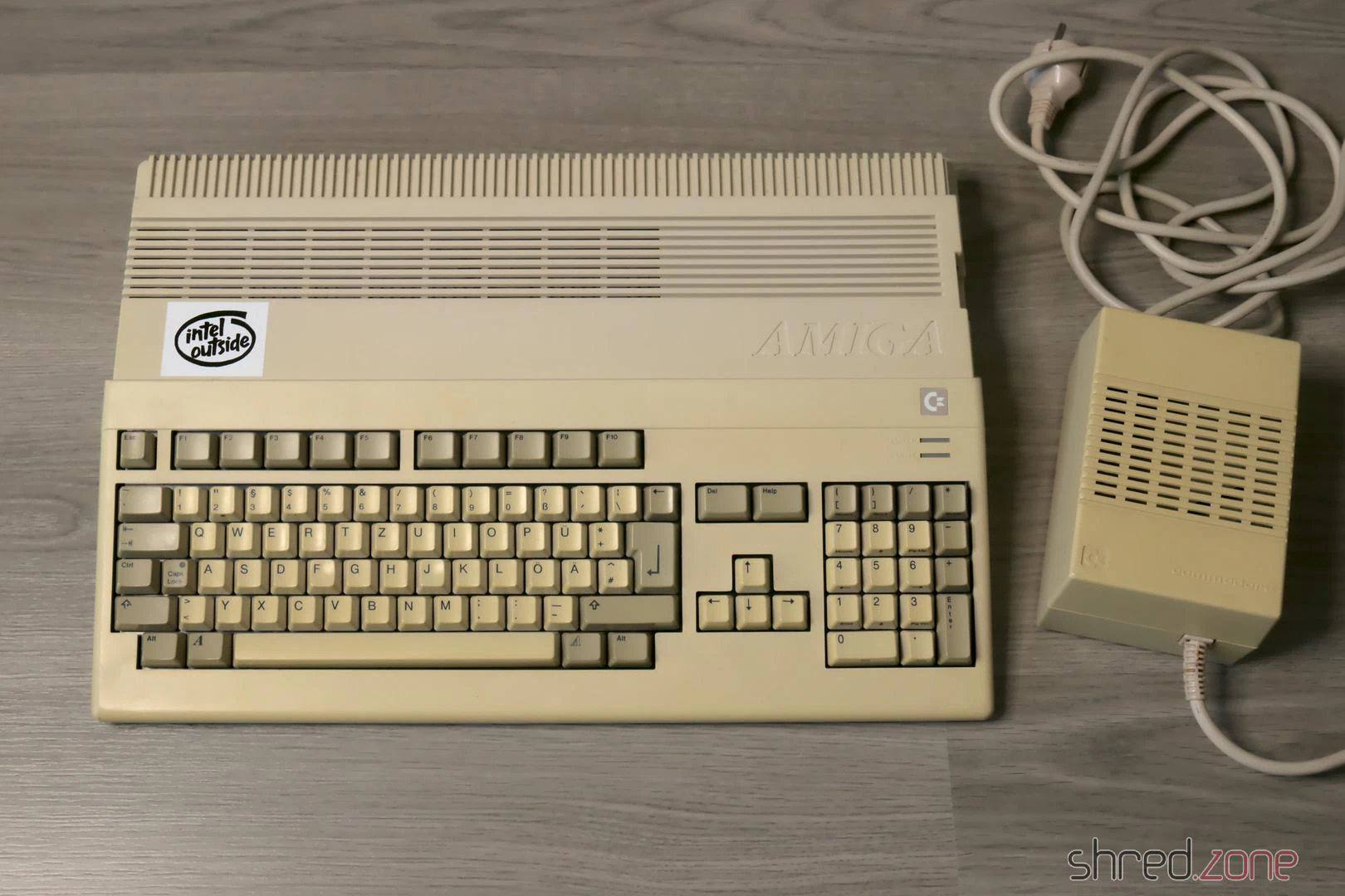
The case is not quite as yellowed as I had feared, nevertheless the ugly “nicotine yellow” has to go. On the right side of the case I had added four switches. At that time the Amiga was rather a commodity, and I didn’t care much about it. Today I scolded my old self for drilling holes into that beautiful case. So there’s one more item on my to-do list: fill the holes.
As for the case, I couldn’t decide if I should have it dyed black, or have it bleached at the CBM Museum Wuppertal (CMW). I couldn’t find a paint shop who would dye plastic though (they only offered varnishing), and the contact to the CMW turned out to be nice, so the case will now be bleached by the professionals there.
I have to admit: My fingers were itching to plug the Amiga into the wall socket and the TV right away. Fortunately I didn’t do that. The circuit board of the power supply looks like it has been soaked in coke:
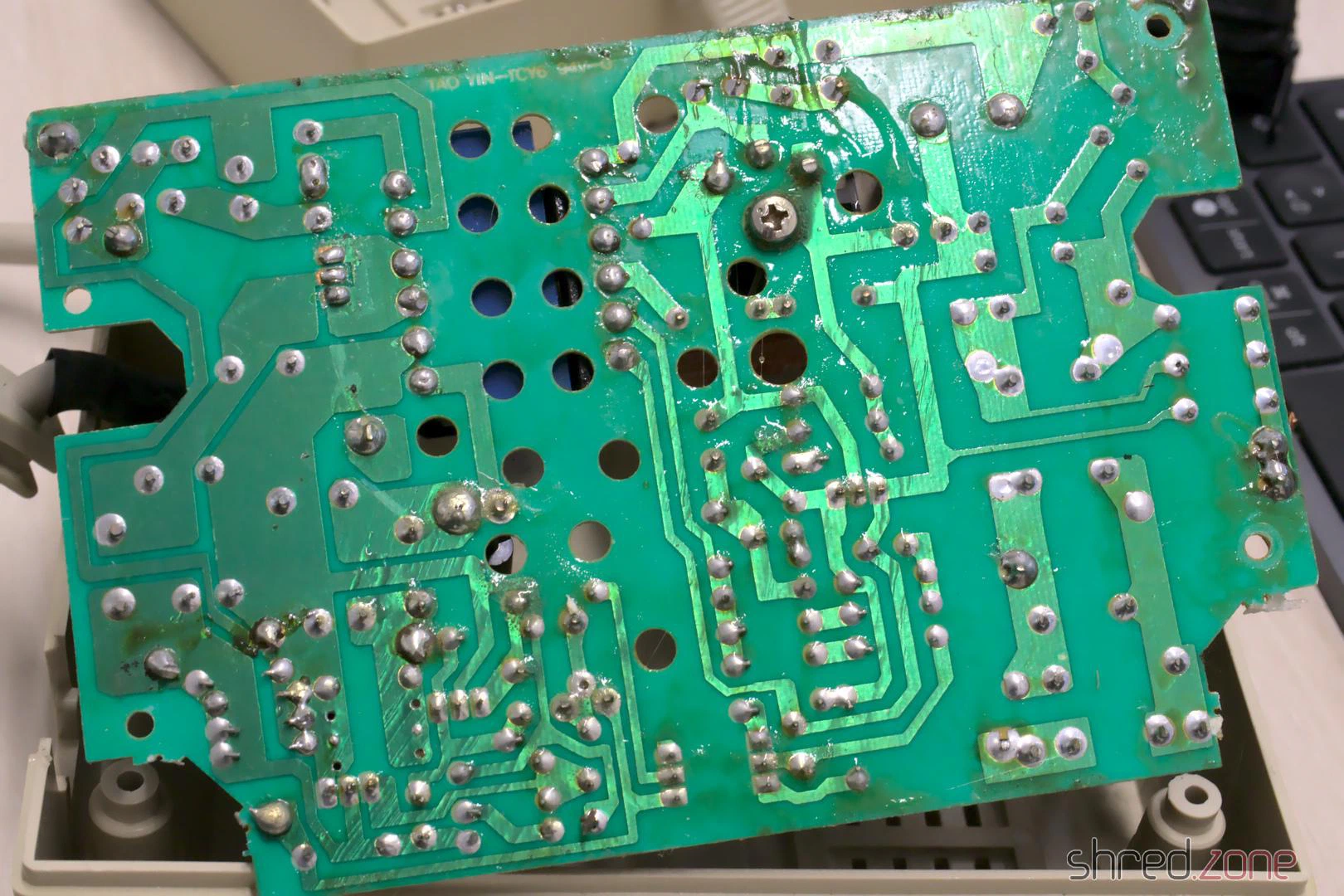
There are no traces of that liquid inside the case, so my guess is a leaked capacitor. Maybe it was this one:
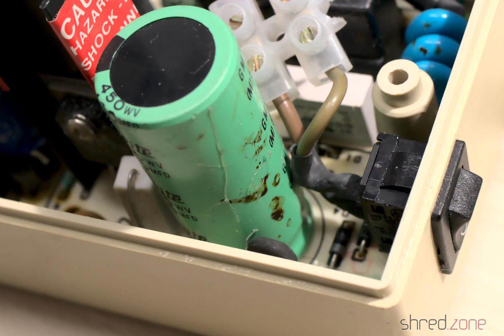
A homemade repair is totally out of the question if mains voltage is involved. Modern switching power supply modules are simply too cheap for that. So the next item on my to-do list is: get a new power supply.
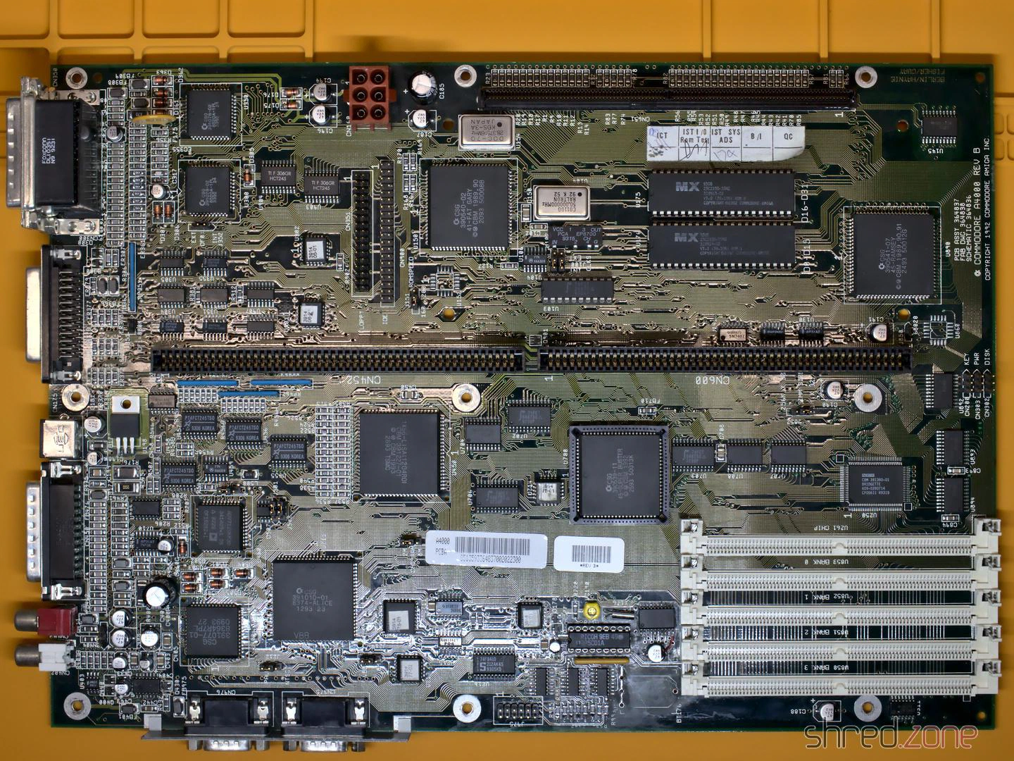
Let’s have a look inside the Amiga. The metal cage is a bit rusty here and there, but all in all still in good shape. The circuit board smells a bit of cellar mustiness, but everything is in its place and nothing seems to be damaged. It all certainly does look very good!
For recapping I inspected all the electrolytic capacitors and listed their values. After that I found out that someone else did that work already. I will replace all the capacitors with premium ones, which sounds more dramatic than it is for cent items. I chose Panasonic caps with a lifetime of up to 10,000 h. The old capacitors were standard types with maybe a tenth of that lifetime.
What’s next? The case is now on its way to the CMW for whitening. I’ve also placed multiple orders for the new power supply, the capacitors, the HDMI adapter and the floppy drive simulator. So let’s wait for the deliveries.