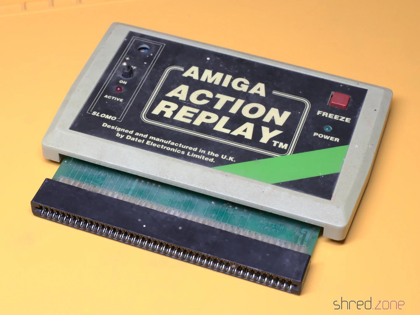
I got this Action Replay MK-I module. According to the seller it was untested, and for that reason sold as defective. It was in a… let’s say very used state. The case was dirty, to a point that it was almost revolting to touch it. A side of the case was cracked open, and a knob was missing. The module must have been dropped at some time.
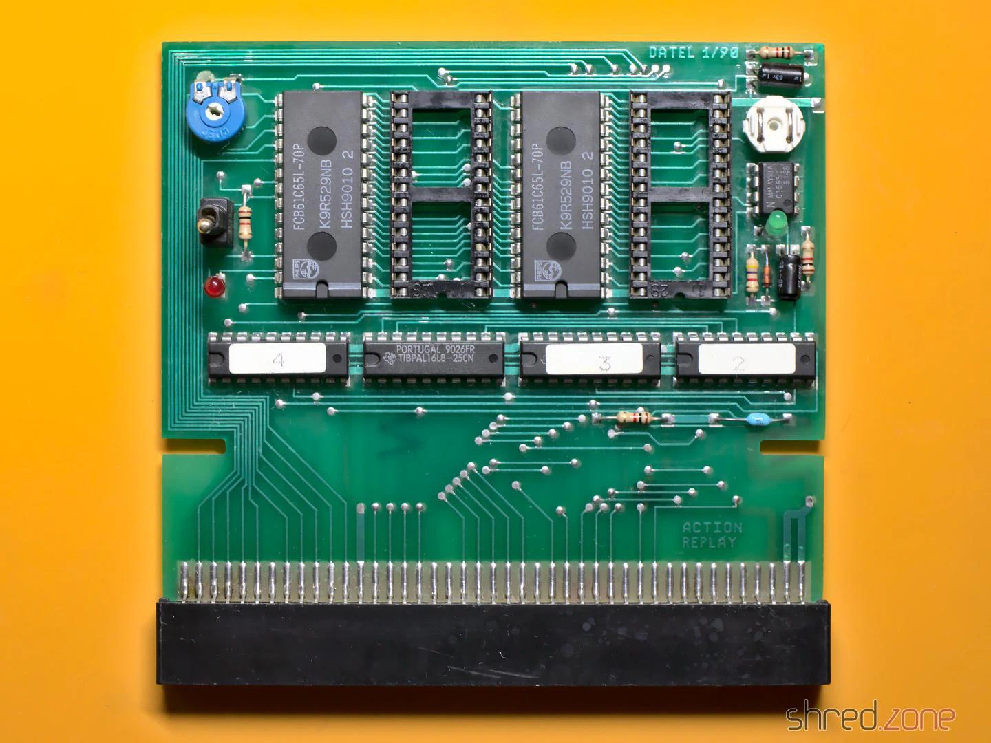
I carefully opened the case. The top and bottom shells are just stuck together, there are no screws, so it was easy to pull them apart. Inside I found some kind of coating on the PCB, so perhaps a drink had been spilled on the module as well. I also found a lot of fine paper dust like from a cardboard, and a small dent at the corner of the PCB that was caused by the drop.
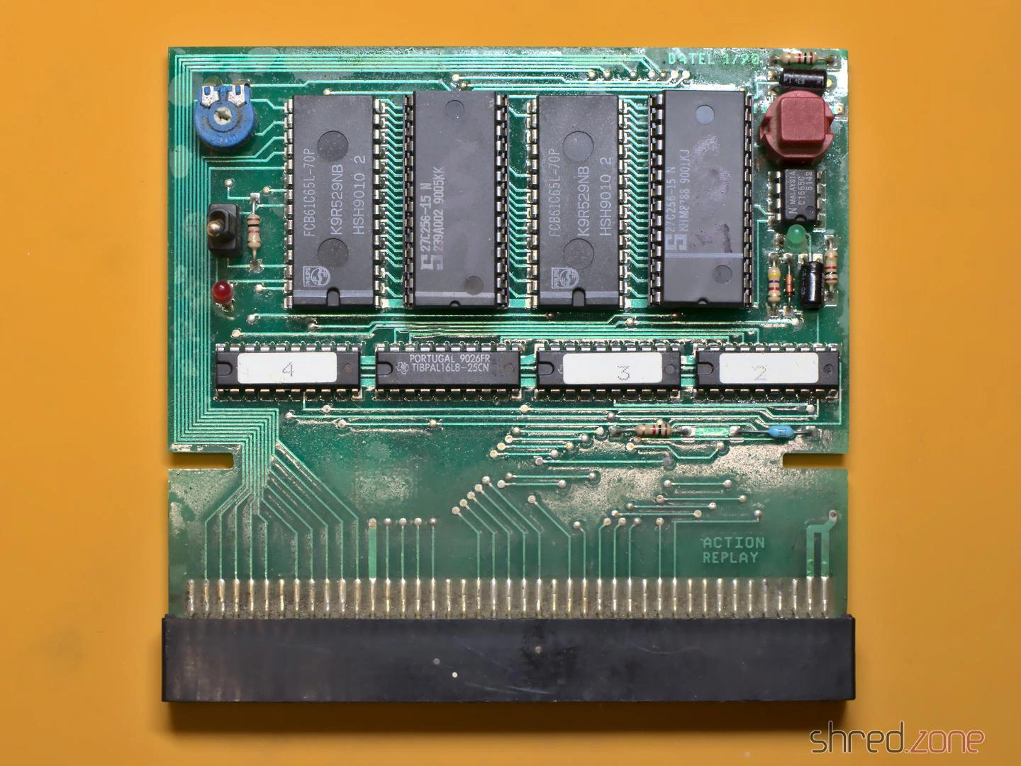
The first thing I did was to give the entire module a proper cleaning in an ultrasonic cleaner, just with warm water and a drop of dishwasher detergent. And yes, I also washed the PCB that way, then dried it off and sprayed it with IPA to remove the last traces of water. That bath did wonders.
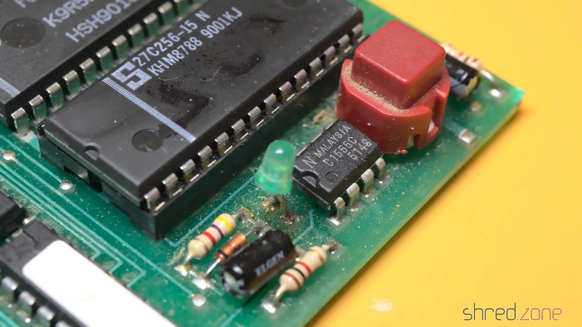
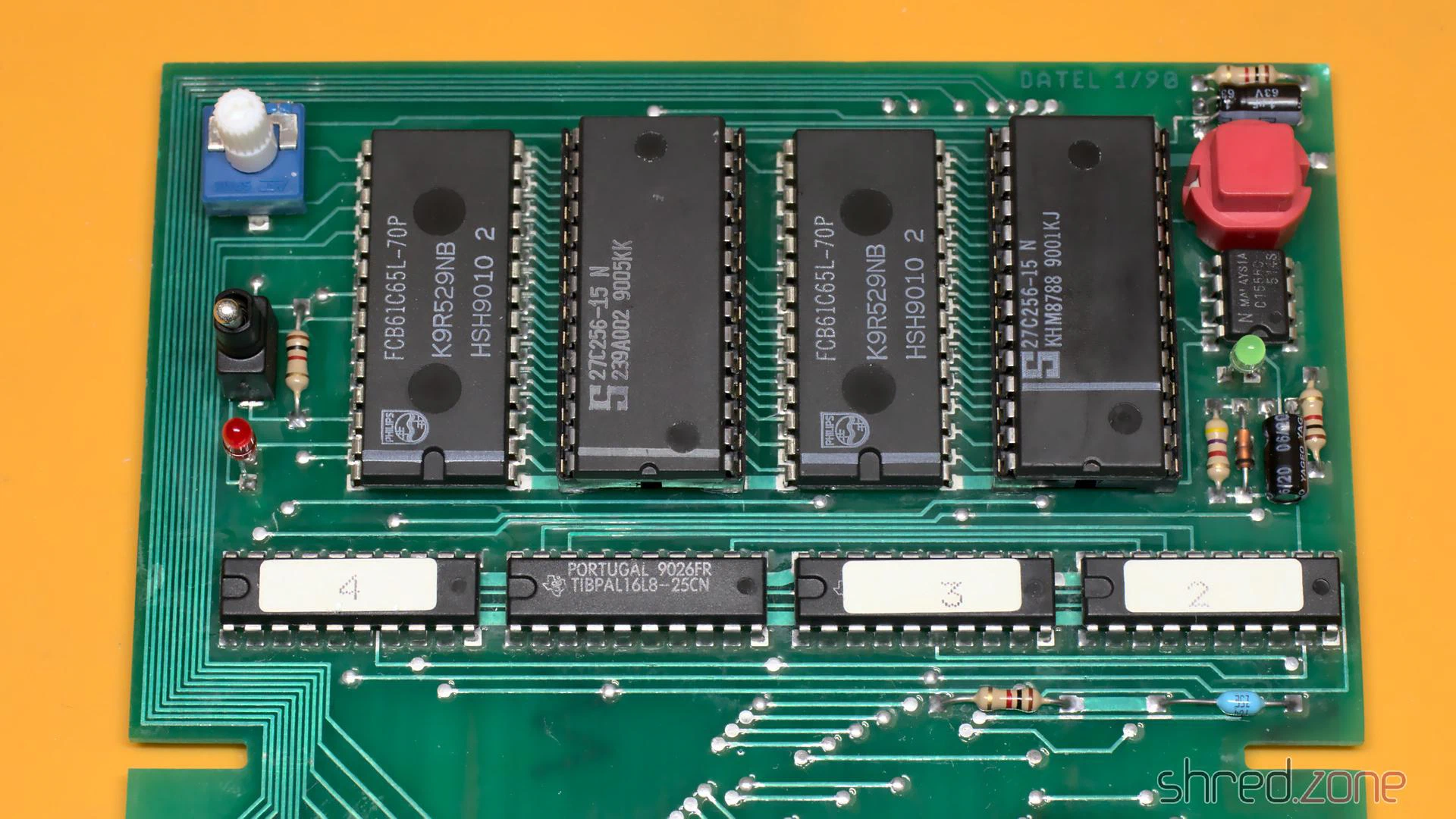
I expected that the dirt also reached the inside of the mechanical parts, so I decided to replace them all. They were a bit hard to find as replacement parts, but still available. As the original knob was lost, I used a different potentiometer that came with a knob. Unfortunately the new one is white, while the original one has likely been black, so I couldn’t fully restore the original outside look.
The case was cracked open at one side because two pins inside were broken off. I fixed the pins with superglue. After that I exposed the case to the sun for a day, which removed quite a bit of the yellowing. Then I could put everything together again. Compared to the original state, the Action Replay is now looking nice and clean.
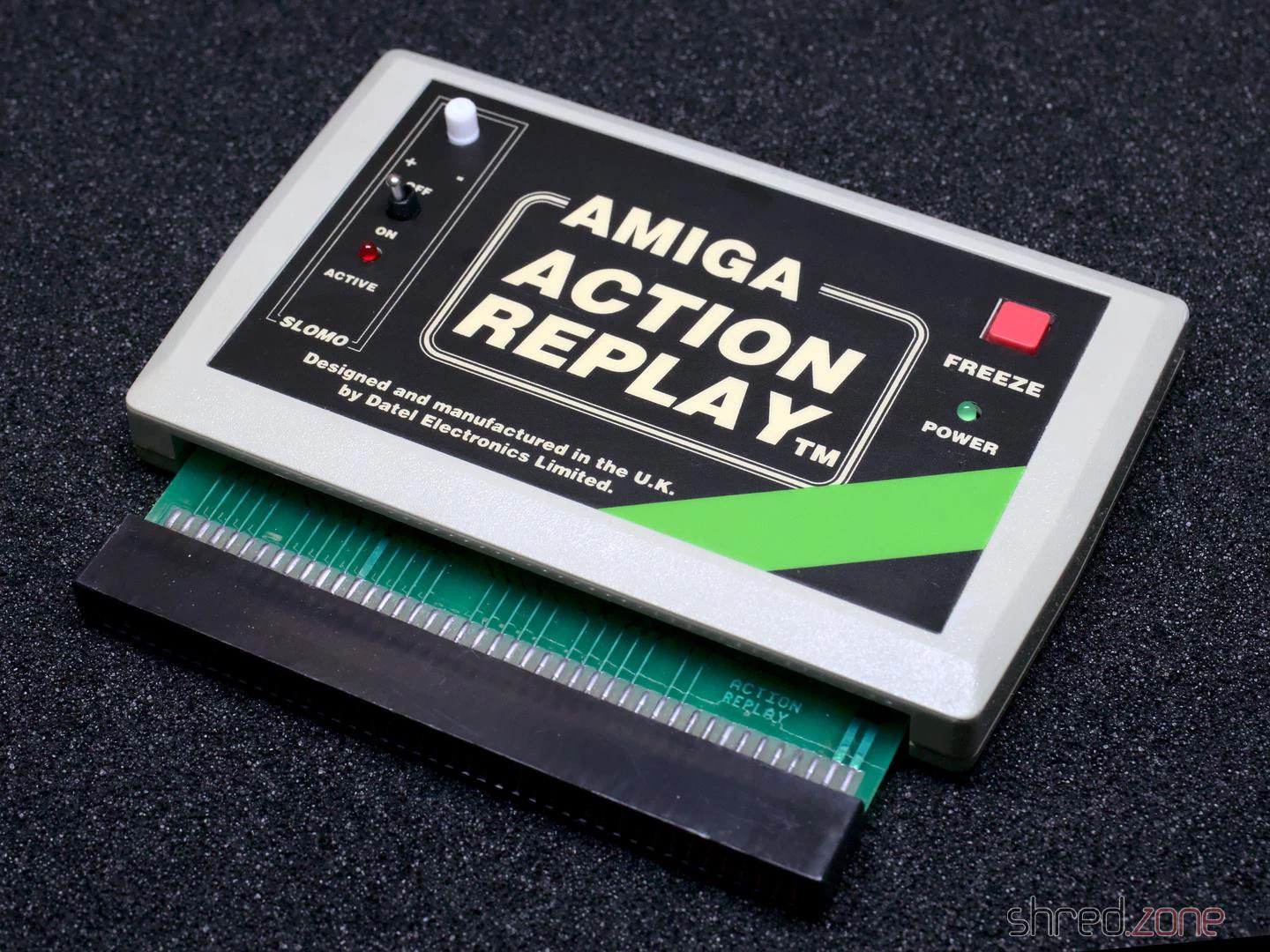
I gave it a test run in my Amiga 500, and it was working fine! Now I have an Action Replay for my Amiga collection. The only sad thing is that it cannot be upgraded to an MK-II or MK-III, as these modules are constructed differently.
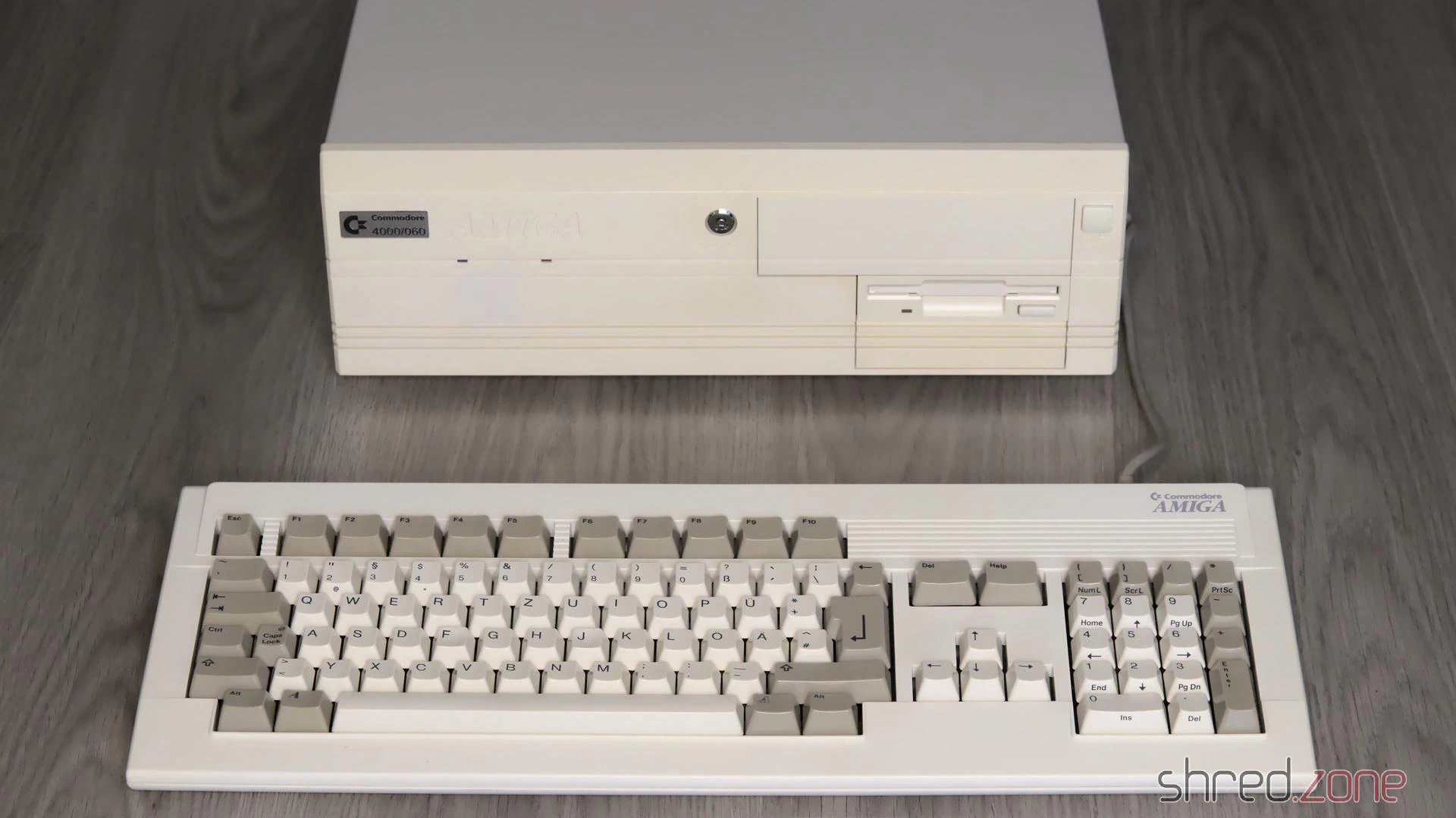
Ever since I got my Amiga 4000, I was pondering about if an Amiga 1200 would have been a better choice. I mean, the Amiga 4000 is nice because it has a lot of space for extensions. But on the other hand, it is rather bulky and heavy, so it isn’t much fun to take it to a friend or a party, unlike the compact and light Amiga 1200.
But why not have both? 😉 I had found an Amiga 1200 offer on the Bay that was too good to be ignored, so I bought it.
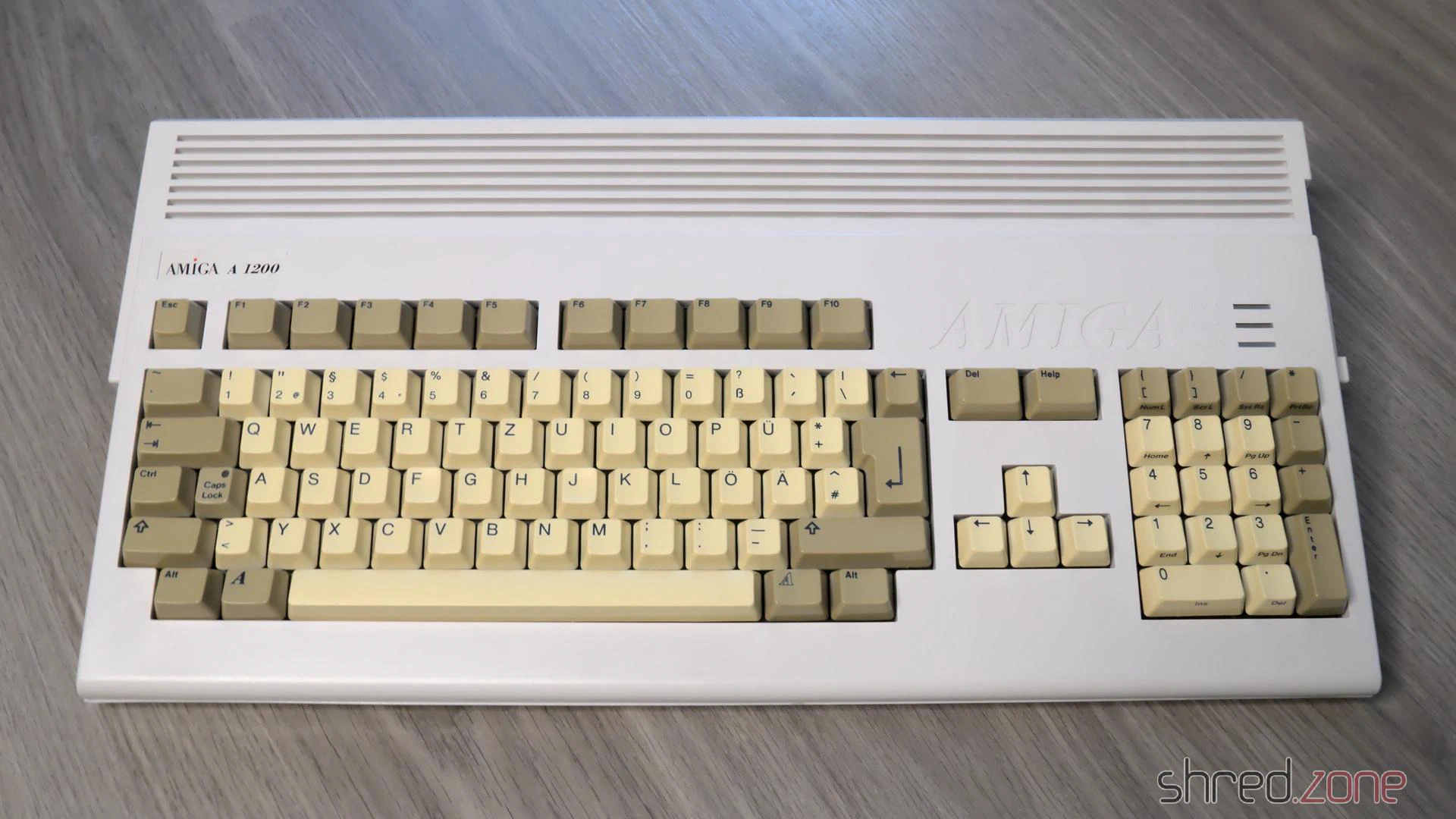
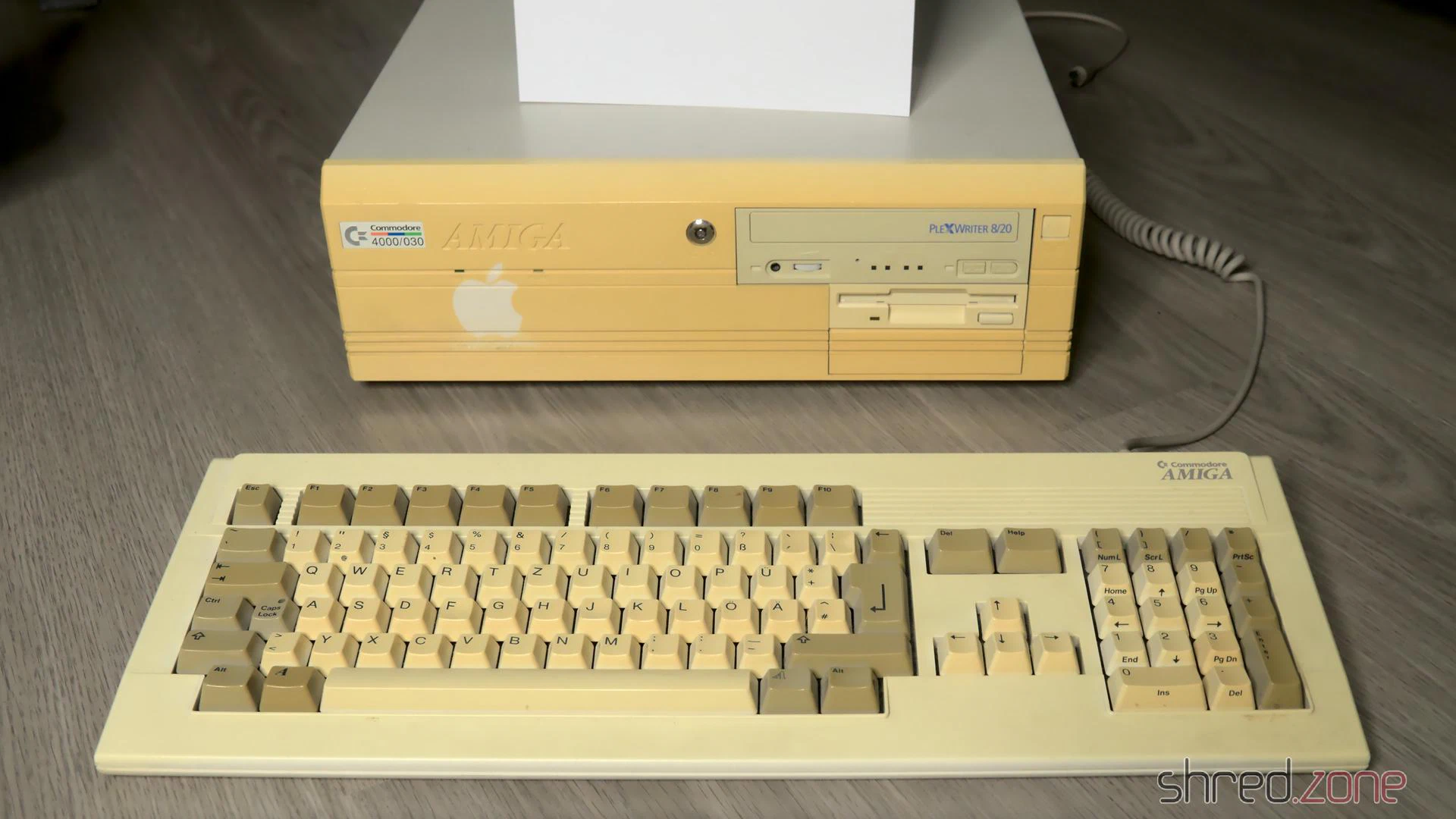
It’s an Amiga 1200 from the days after Commodore went belly up, and when Escom took over and sold the last Amiga stocks. The good news is that the Escom cases were made of ABS with an anti-UV treatment, so they will never yellow. The bad news is that the keycaps were not treated, and are very visible yellowed by now.
I sent the keycaps to the experts at the CBM Museum Wuppertal for whitening. The case itself is almost in a mint condition, all it needed was a bath in warm dishwater.
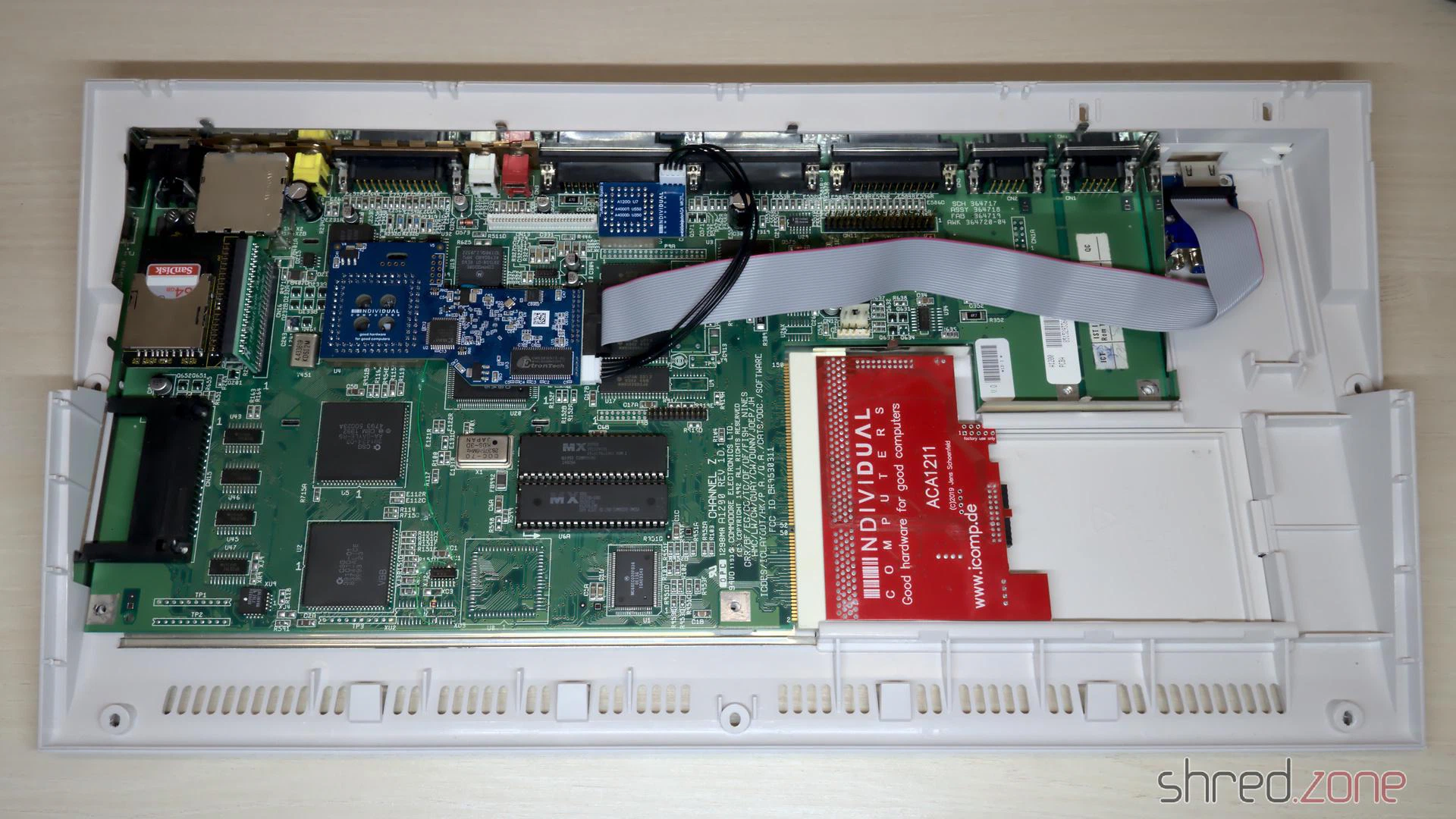
Let’s take the computer apart and have a look inside.
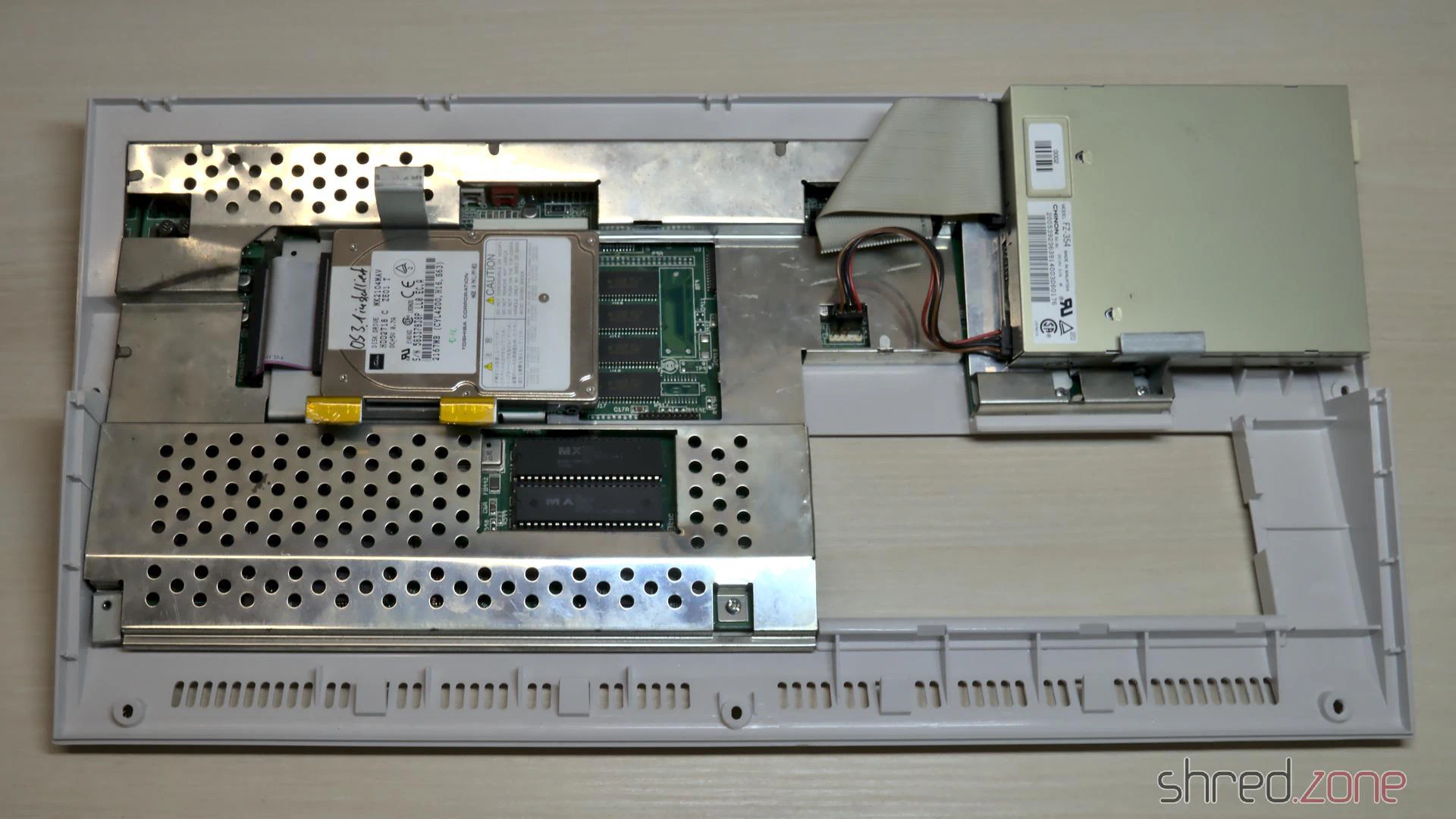
There’s a 2.5" hard disk, which turned out to contain a Workbench, a few games, and also many bad sectors. I’m going to replace it with an SD Card solution anyway. The shielding has a bit of flash rust and was bent around the ROMs, probably from forceful prying out the ROM chips with a screwdriver. Besides that, the overall status is quite okay.
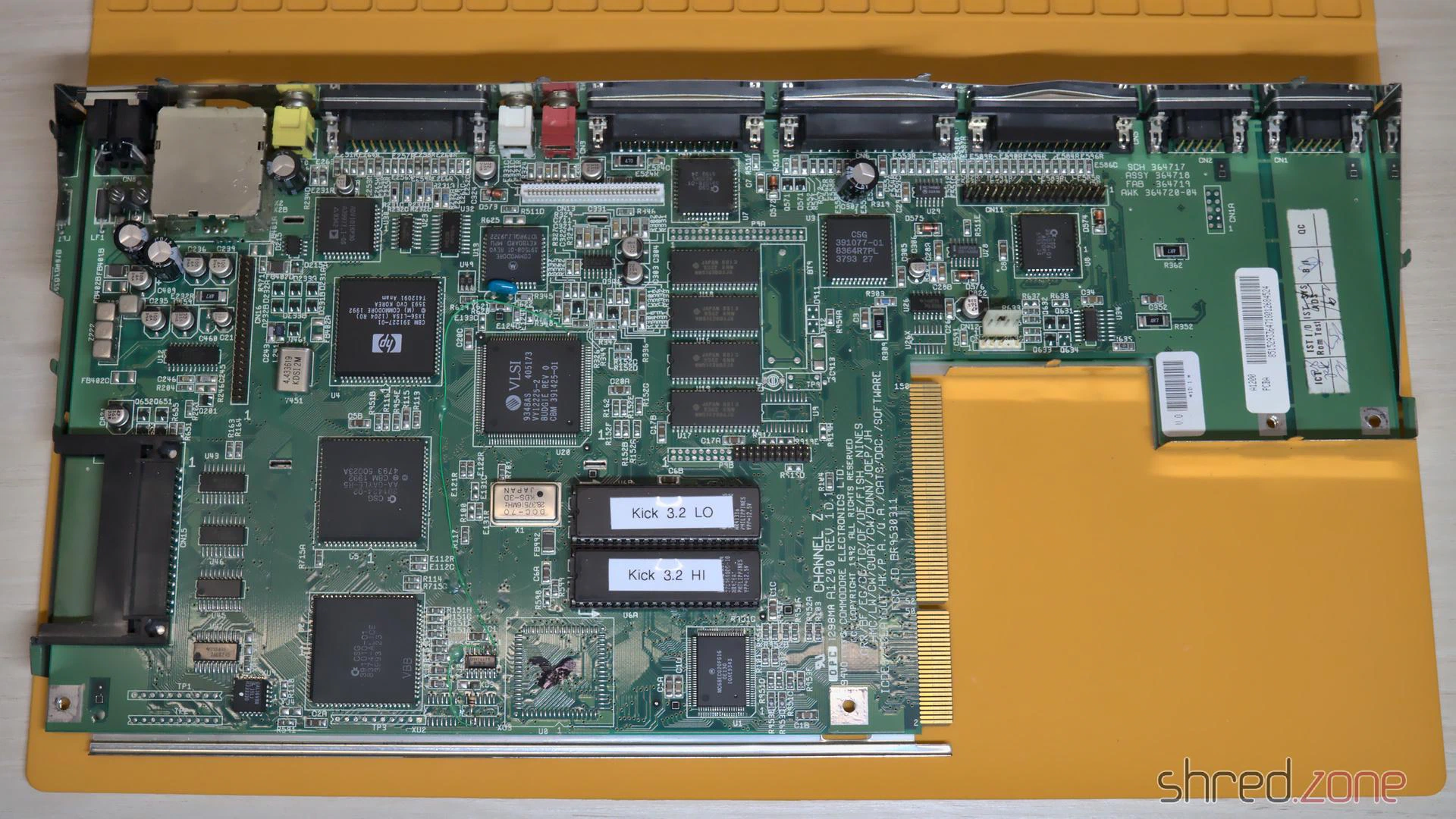
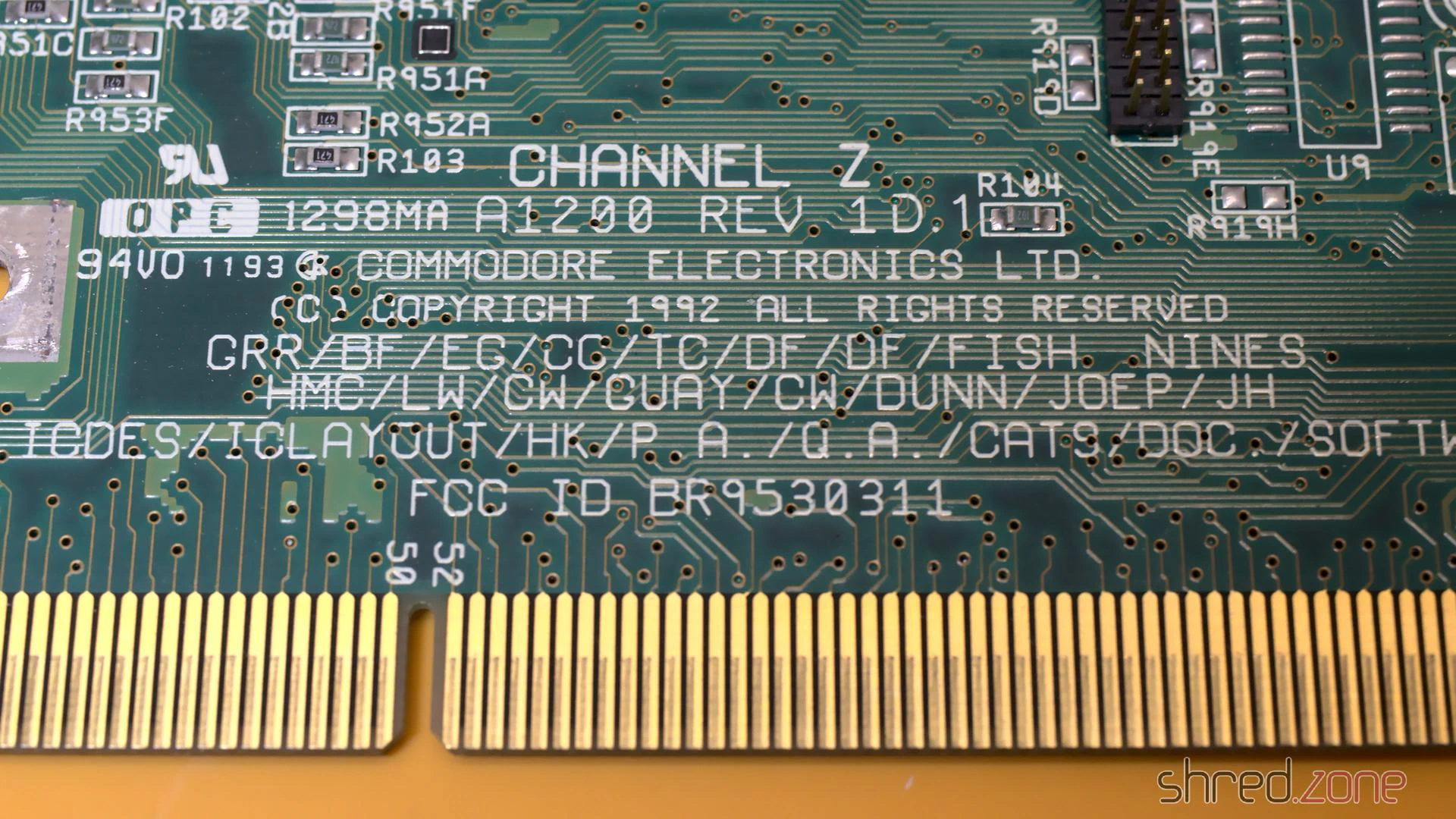
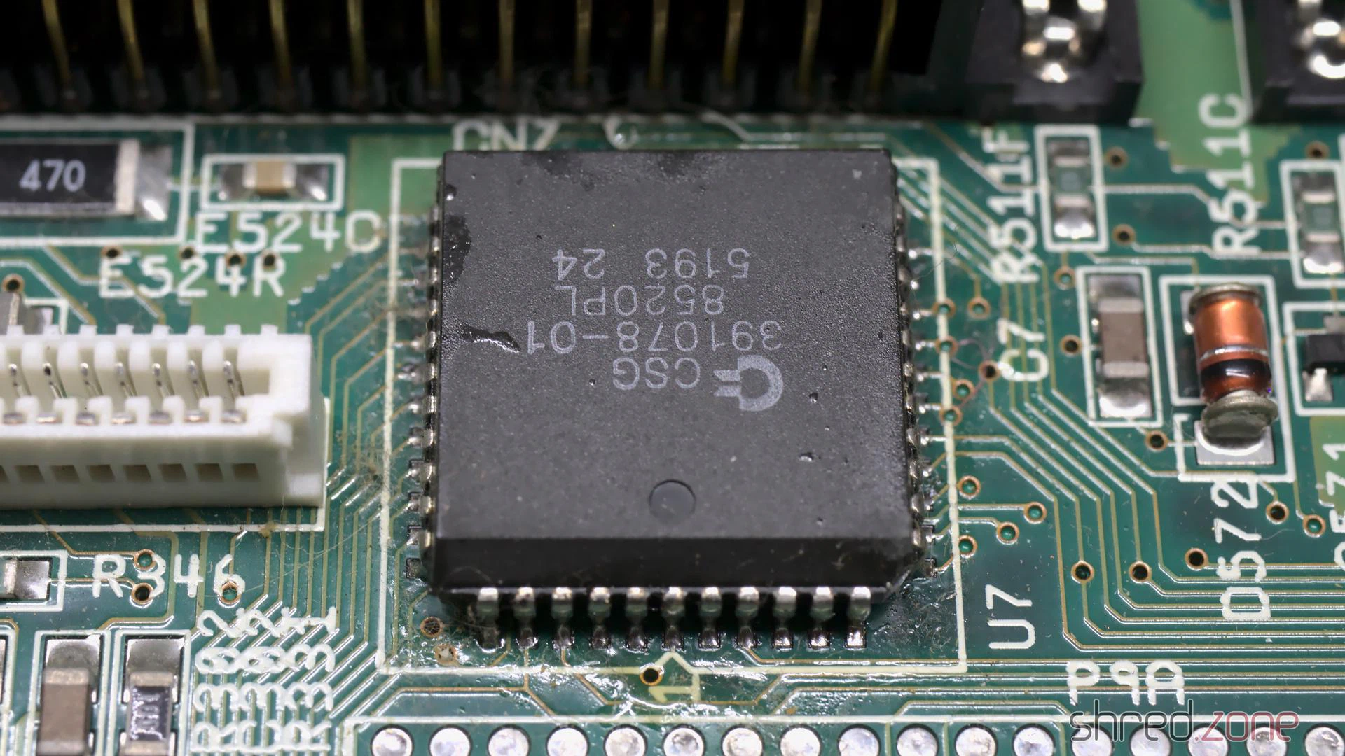
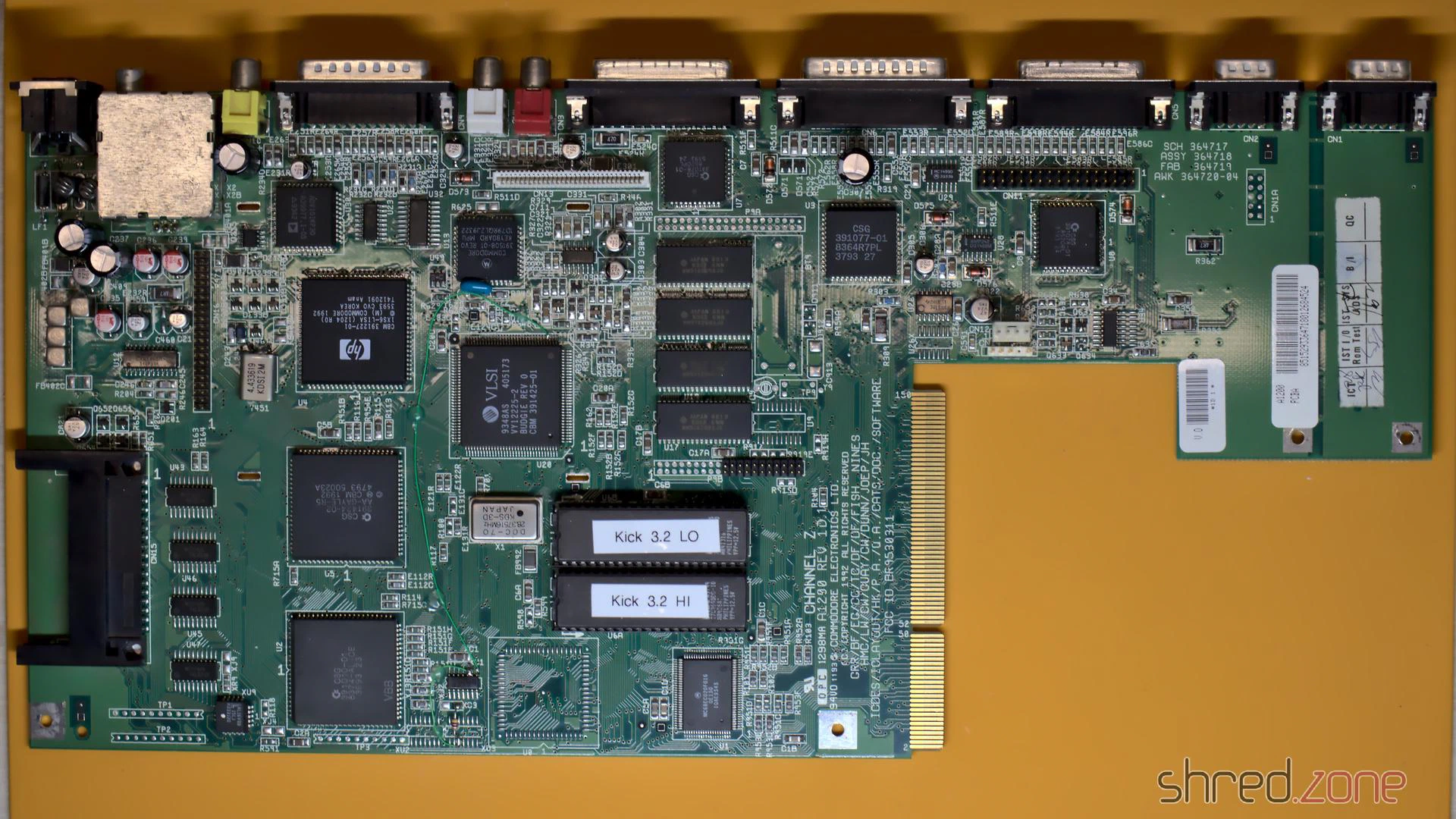
Under the shielding, I found the mainboard in a good condition, especially without flash rust on the modulator. To my surprise, it is a Rev. 1D.1 board, which was actually the first broadly sold board revision. In one of the last Amigas that have ever been produced, I had rather expected to find a revision 2 board. Anyway I was lucky because the 1D.1 revision is said to be the most stable one, and it also has a good Lisa chip that was manfactured by HP. On both CIA chips I found traces of flux, so the board seems to have been repaired before.
According to my contact at the CBM Museum Wuppertal, Escom sold everything they could find at the Commodore remainders. Allegedly they also produced “new” Amiga computers with refurbished mainboards. Maybe this is one of them?
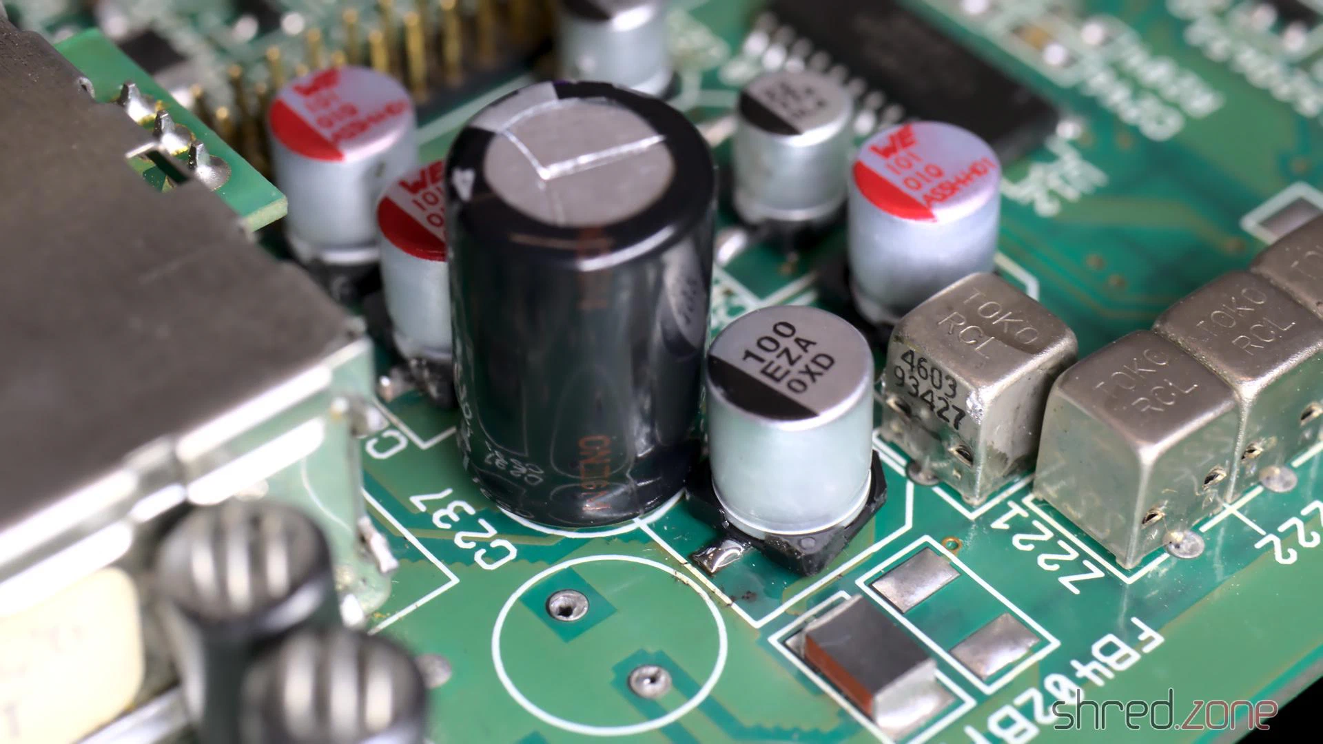
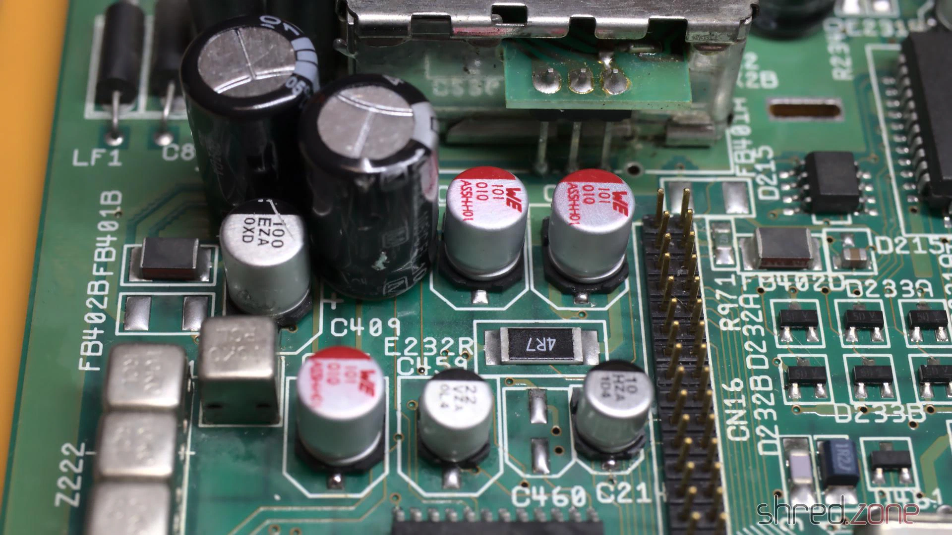
I first inserted diag ROMs and checked the hardware, but found no problems, so I upgraded the system to AmigaOS 3.2. The next thing on my to-do list was to replace the electrolytic capacitors, as they tend to leak over all those years, causing damage to the PCB. I have already done that on my Amiga 4000 before, but on this model the space was a bit more limited. I even had to remove a freshly replaced SMD capacitor because another capacitor did not fit next to it any more.
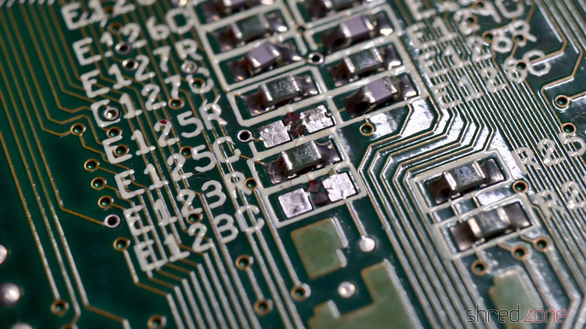
To enhance the stability of accelerator boards, it is recommended to remove the capacitors E123C and E125C on the bottom side of the PCB. The easiest way is to use two soldering irons like a pair of tweezers.
After a thorough wash with IPA, the board was then ready to move back into the case.
I want to modernize the Amiga so it can be connected to a HDMI monitor. The RGB to HDMI solution of the Amiga 500 won’t work on the AGA chipset though, so I decided to get an Indivision AGA MK3 from Individual Computers. It is plugged onto Lisa and one of the CIA chips, and offers an HDMI output even with sound. (Which is quite an accomplishment, as both chips are not connected to a sound line.)
Since I was on it, I also extended the memory with an ACA1211. Unfortunately it turned out that AmigaOS 3.2 is incompatible to the ACA1211, and the system won’t boot in this combination. I had to return to the original AmigaOS 3.0 ROMs again. Eventually I traded the ACA1211 for an ACA1234, which is also an accelerator and works fine with the latest AmigaOS.
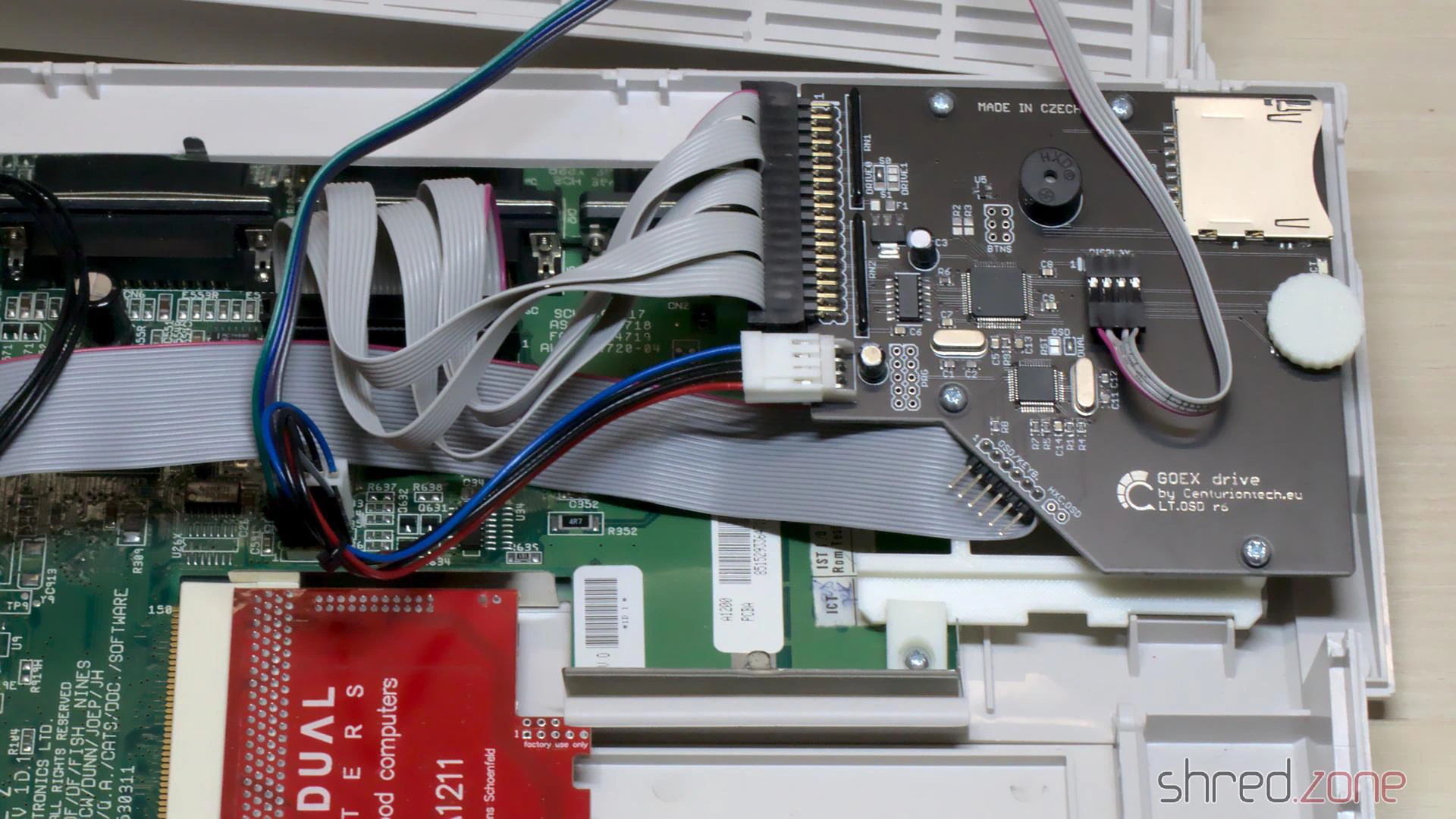
To make the wire mess complete, I replaced the floppy disk drive with a GOEX drive from Centurion Tech.
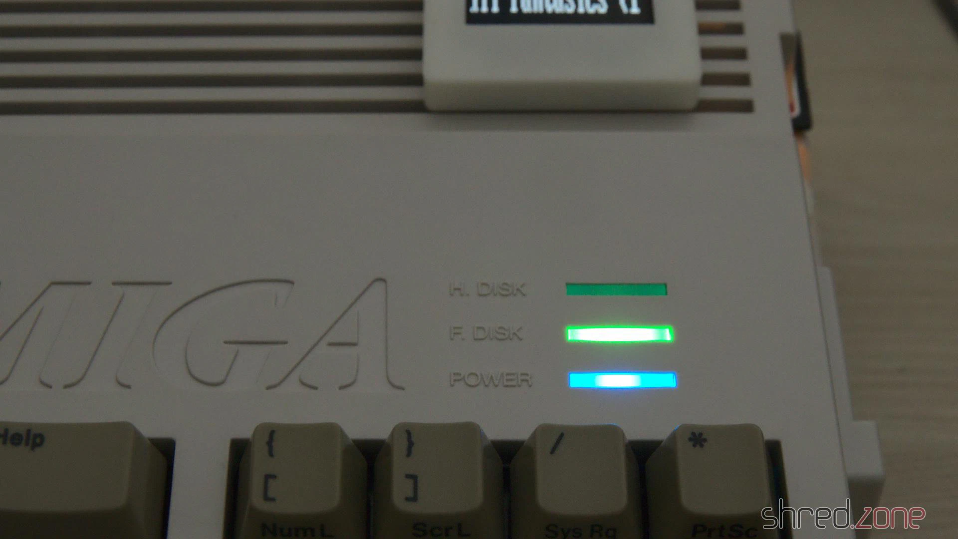
Centurion also offers LED boards with customized colors. I have picked blue as power LED, green as floppy drive LED, and red as harddisk LED.
In the meantime, I got the whitened keycaps back. They were almost white again, but sadly there is still a slight, but visible yellow tint. Maybe I will buy a new set of key caps once they are available. The Amiga would then look as new.
The original Escom label is just a cheap sticker. It looks ugly to me, so I replaced it with a replica Commodore badge.
And then, for the first time after my purchase, I could close the Amiga 1200 case again.
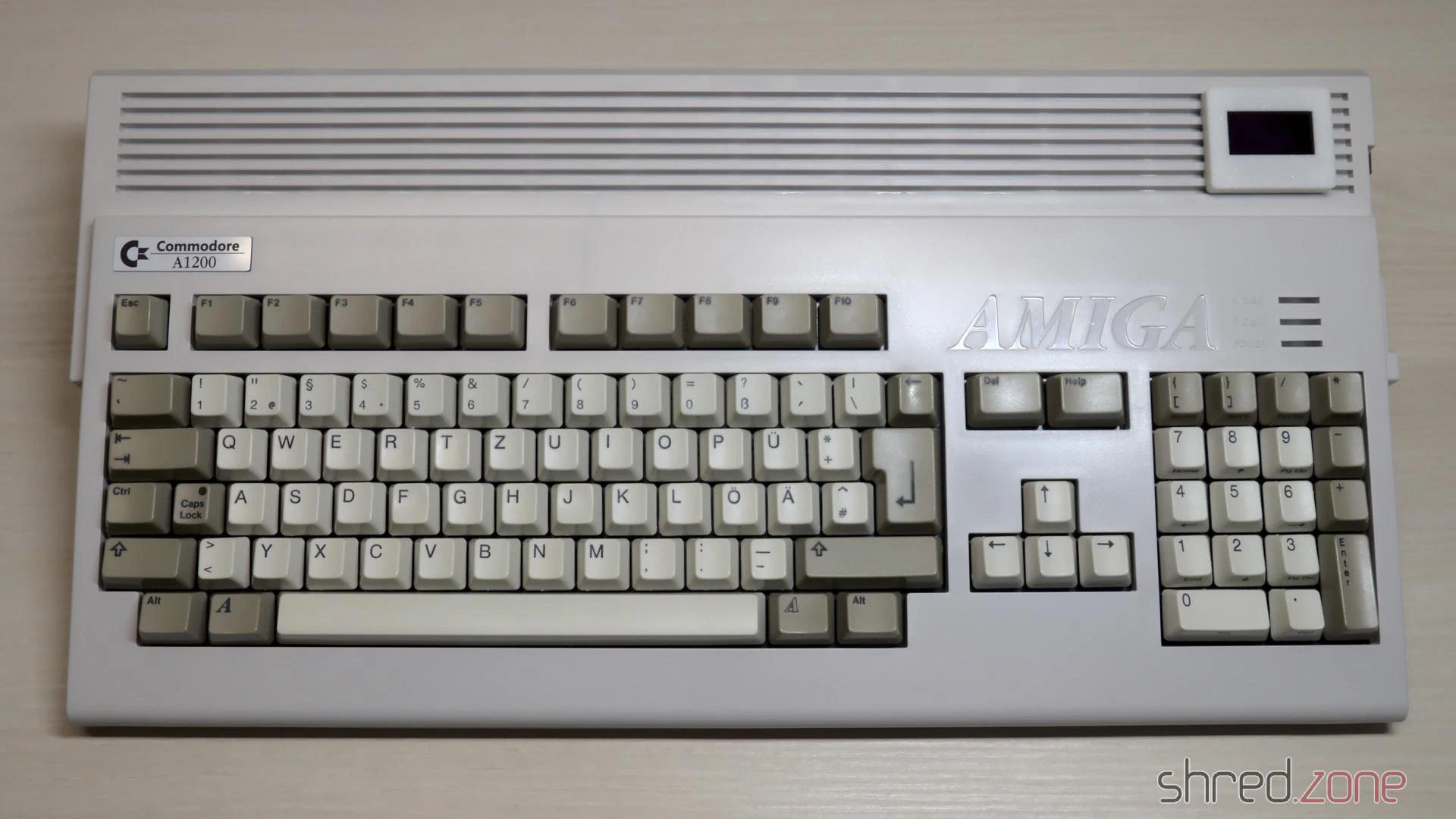
Please welcome the newest addition to my Amiga collection!
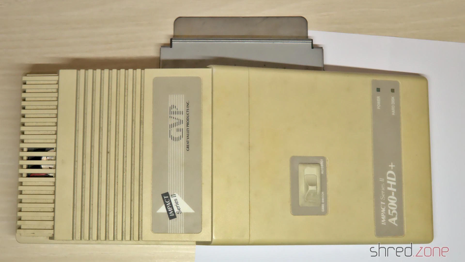
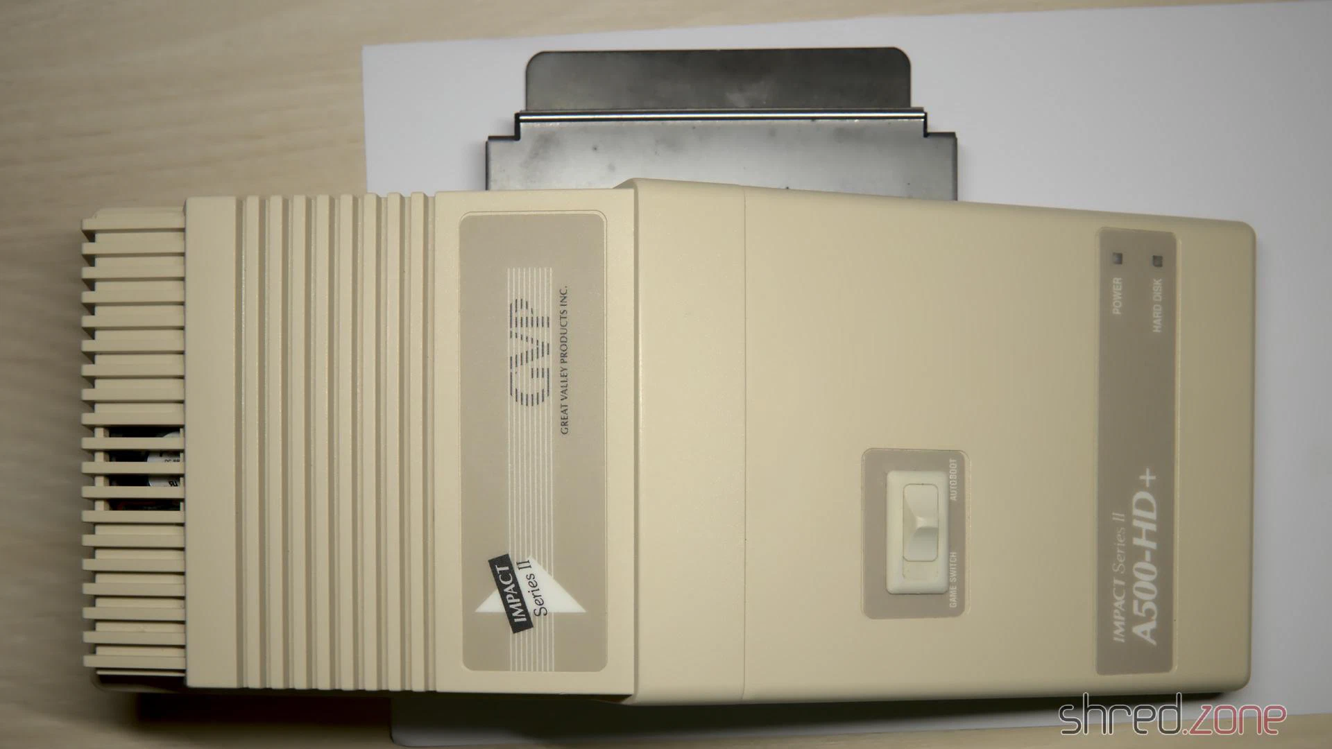
One year or so after I got my Amiga 500, I extended it with a GVP Impact Series II A500-HD+ SCSI host adapter and a 45MB harddisk. It retired together with the Amiga 500, and was stored in the basement for decades. But while the Amiga survived the years in a surprisingly good state, the GVP had suffered from the moisture. The case was yellowed, but also got mold stains, and the metal frame got some flash rust.
All in all, it seemed to be in a bad shape that was difficult to restore. But on the other hand, it would be sad to write off this nice piece of hardware, while all the other Amiga stuff got a general overhaul.
I sent the case to the CBM Museum Wuppertal for cleaning and whitening. It was a bit embarassing to send it in that bad condition, but they said it can be cleaned and will then look as good as new. Let’s see if they can do miracles.
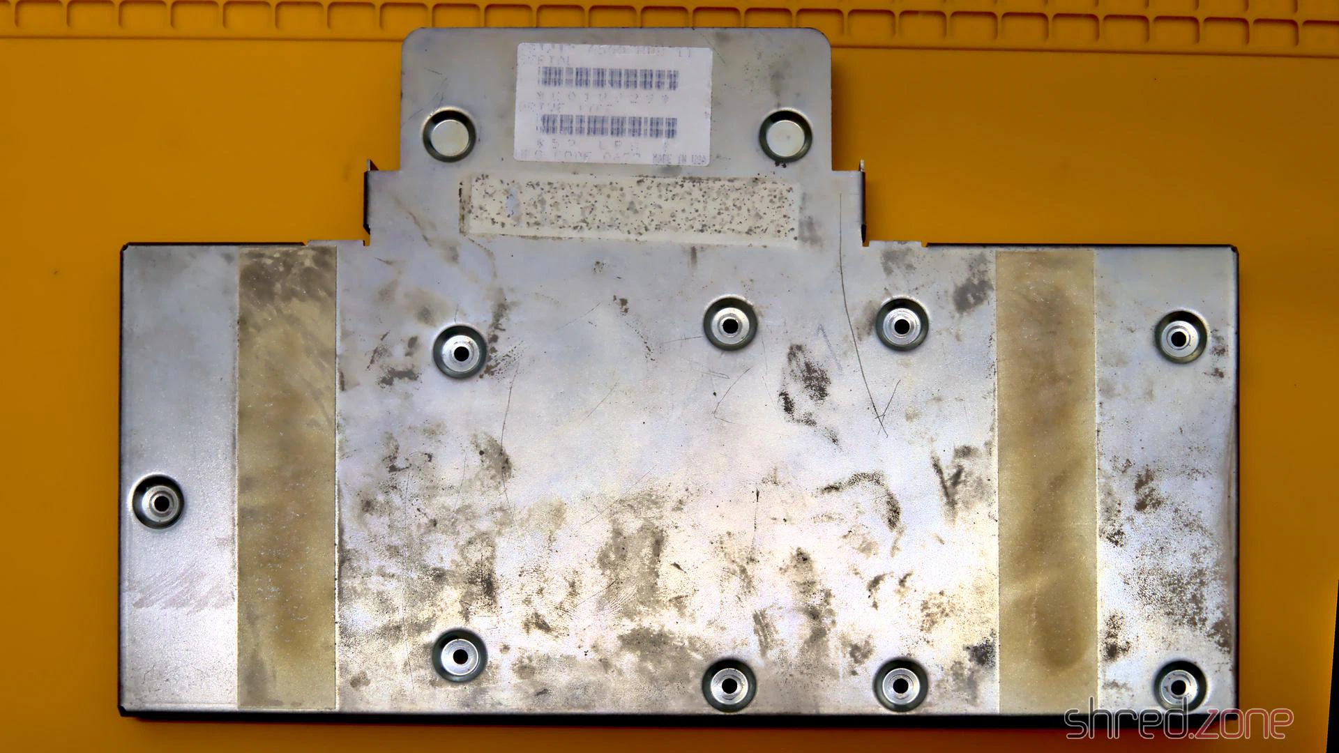
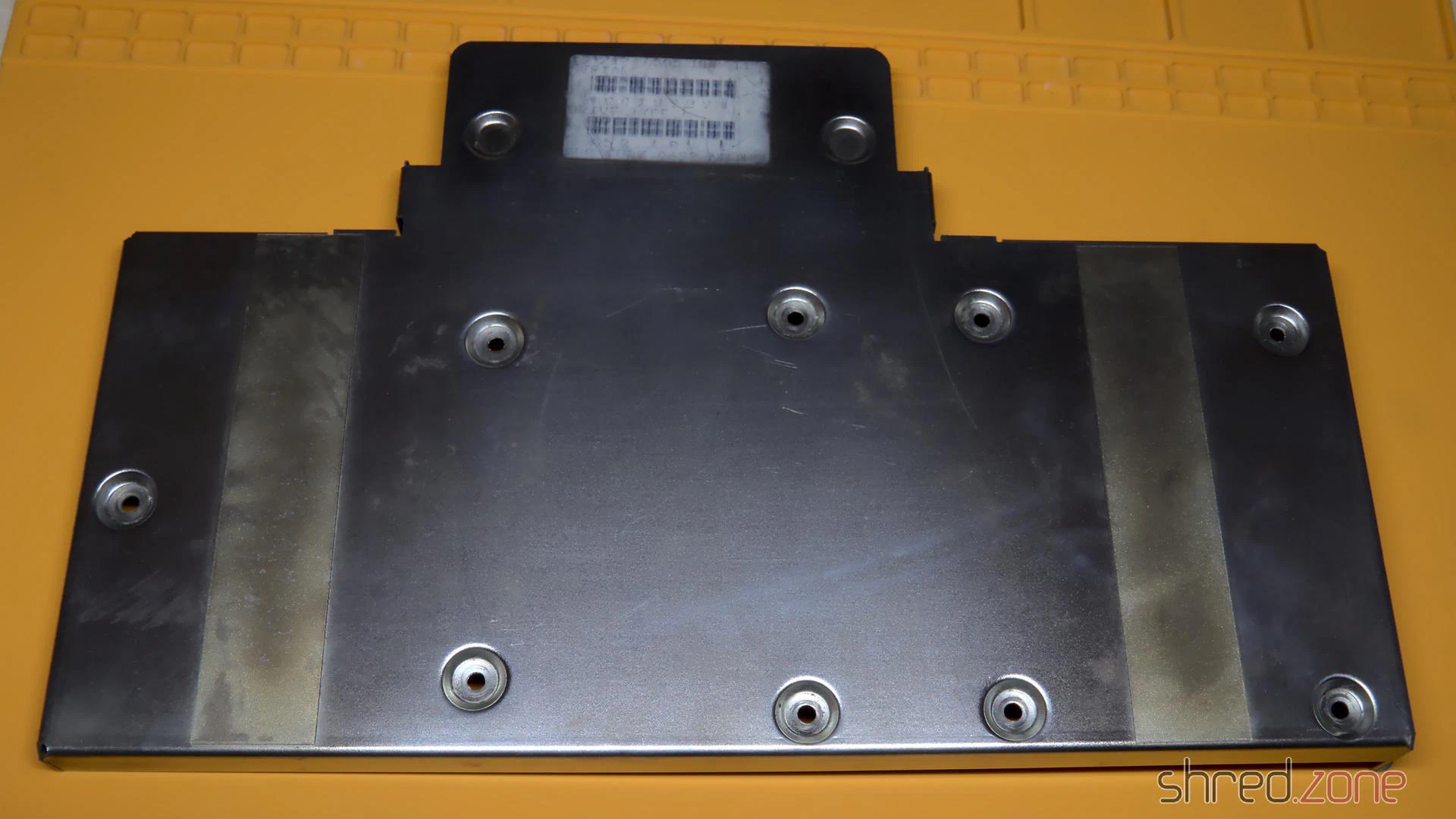
Flash Rust
The base frame had a lot of dirt and flash rust from the storage, especially in the areas that are frequently touched. I used some Nigrin car metal polish paste to clean it, but probably every kitchen metal polish would have done the job as well. It was a bit of work, but after that it almost looked as new.
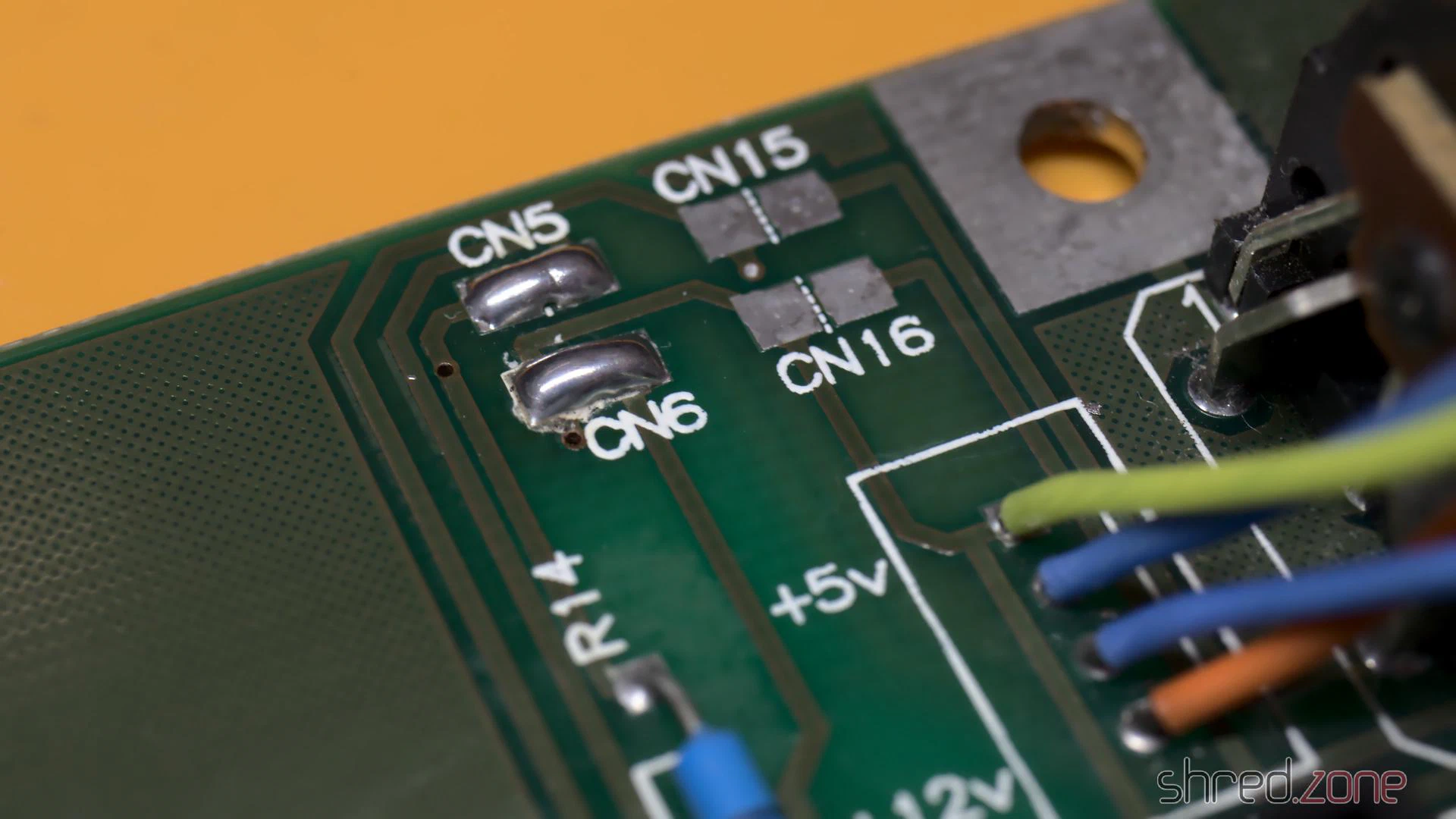
Self-Powering
There have been two things that were always annoying me on this controller. One was the tiny fan that was supposed to cool the harddisk, but produced a lot of noise. The other one was that a separate external PSU was needed to power the harddisk.
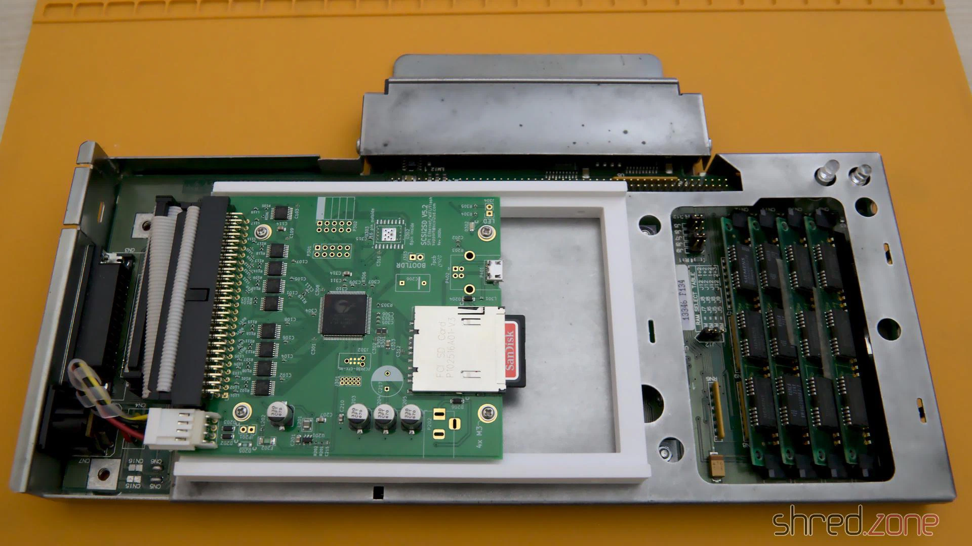
I always wished that the controller would just source itself from the Amiga, but it was clear to me that the mechanical harddisk was drawing too much power for that. The original Fujitsu drive consumed about 10W! With a SCSI2SD adapter, the power consumption is considerably lower, so a self-powering is feasible. The SCSI2SD V5.2 adapter draws only about 10mA, or 0.05W.
The controller can easily be modified to get its power from the Amiga. There is a blog post by davem2 explaining it. All one needs to do is to bridge the CN5 and CN6 pads with some solder.
Since the SCSI2SD adapter also does not need active cooling, I could finally keep the loud case fan disconnected for good.
After the modification, make sure never to connect the GVP PSU to the controller again. It would power the Amiga via the card connector, which is very likely to cause damage to your hardware. Also, do not use mechanical harddisks after the modification. If you want to keep using the original PSU instead, you should let a technician check it first.
Firmware Upgrade
By a lucky chance, I found the latest firmware v4.15 in Ralph Babel’s Amiga archive. By another lucky chance, I also found a 27128 EPROM in my spare part box that was once stripped from an old mainboard.
The original firmware would have worked fine as well, but if there is an opportunity for a free update, why not take it?
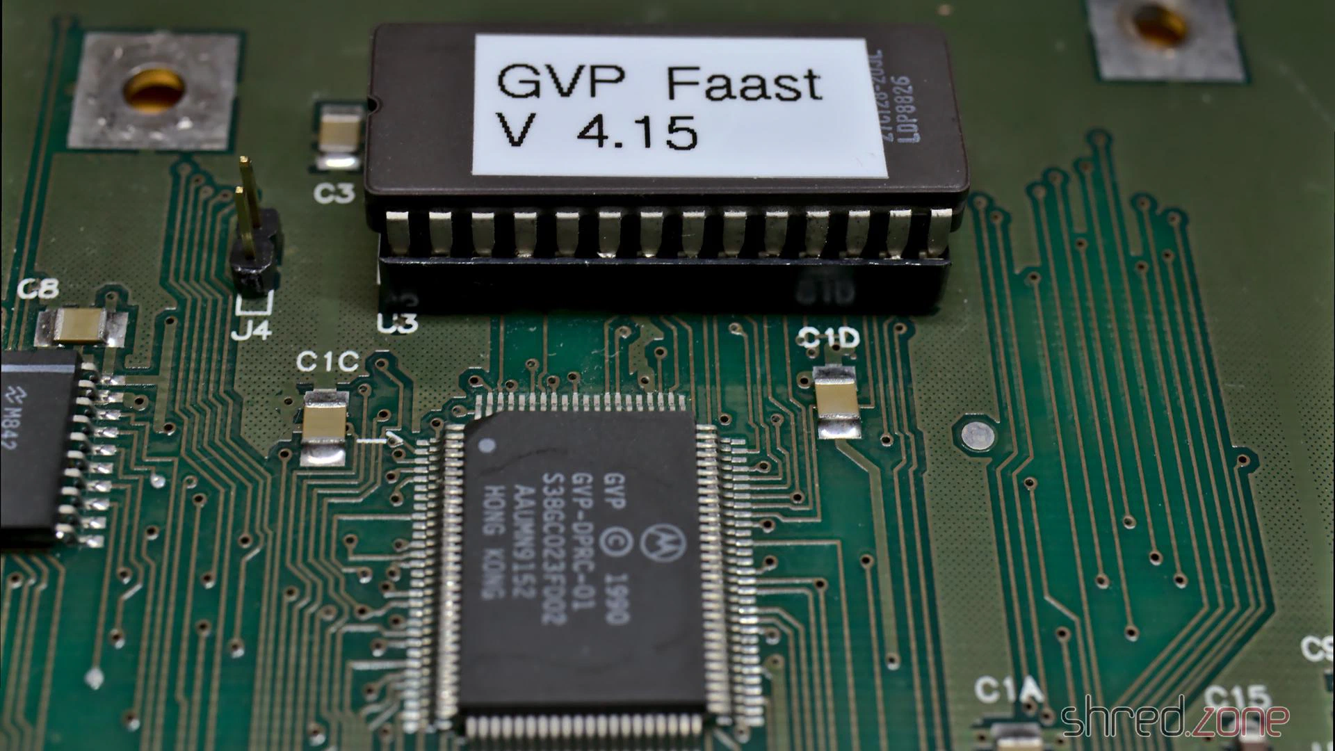
If you should use a 27256 EPROM instead, make sure to burn the image twice, as only the upper half of the memory will be accessed by the hardware.
Final Works
As there are no electrolytic capacitors on this board, there is no need for recapping. I still did a minor modification: I replaced the LEDs with blue (power) and red (disk) ones, as it became a kind of signature color for all my computers.
After that, I gave the board a thorough bath in IPA, and cleaned the edge card connector with a contact cleaner.
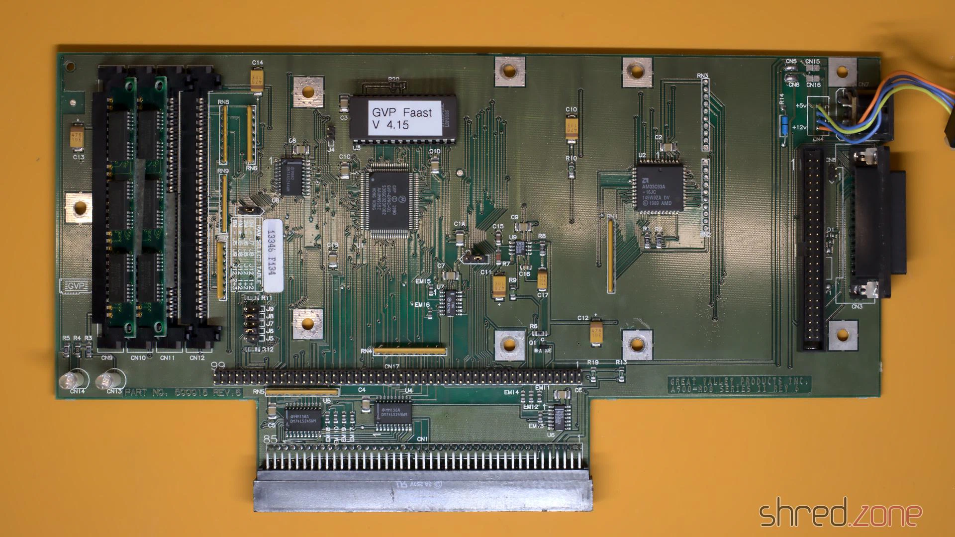
I also found two 1MB/70ns 30-pin SIMM modules for a few Euros on the Bay, so I could double the available Fast RAM to stunning 4MB in total. (Remember to change the jumpers accordingly, as there is no automatic detection.)
Reassembly
Meanwhile the CBM Museum Wuppertal had returned the cleaned and whitened cover. They did an excellent job! The case looks almost as good as new. The mold and dirt stains are gone, and the whitening brought back the original “Amiga beige” color.
As the SCSI2SD adapter is delivered without any kind of mounting frame, I had to 3D-print one myself. Unfortunately it collided with the case fan, so eventually I just removed it completely.
And that’s it. The GVP harddisk controller is reunited with its Amiga 500 again. I am sure they have missed each other. 😉
The ugly duckling finally became a beautiful swan again!
In the first part, I took the Amiga apart and repaired the main board. In this second part, I will take care of a new PSU, and then I will put the system back together.
New PSU
There are also capacitors in the PSU that dry out over the years and need to be replaced. But as I’m not a trained technician, I keep my hands off all kind of hardware as soon as mains power is involved.
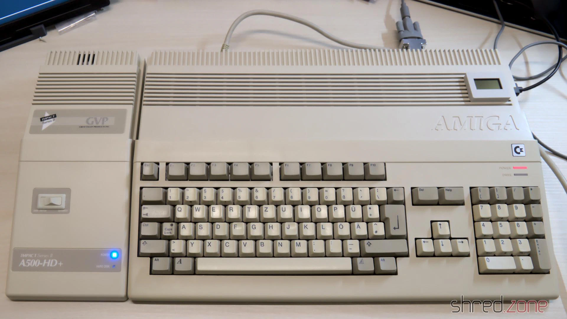
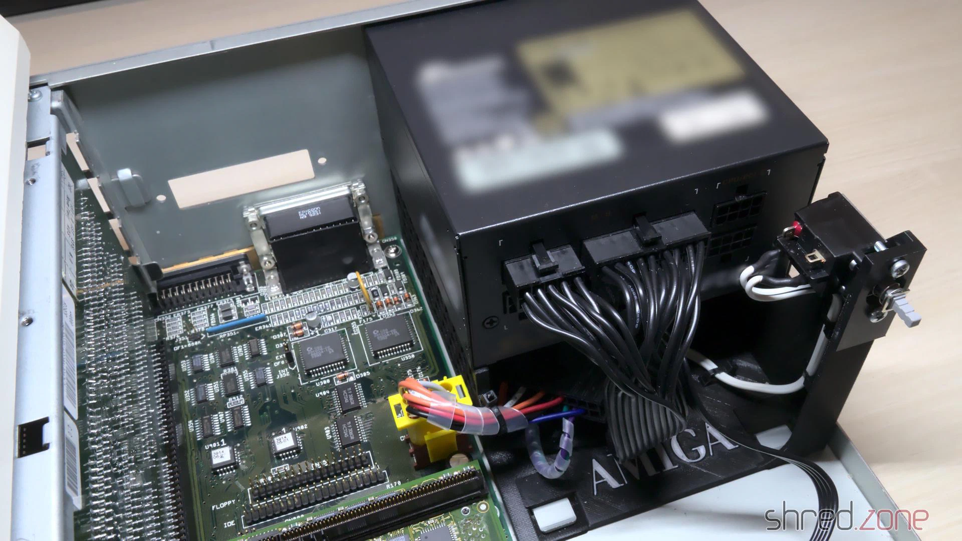
Surprisingly, a standard SFX form factor PSU perfectly fits into the power supply opening at the back side of the Amiga case. Even the two screw holes of the case match perfectly, almost as if the SFX form factor was just invented for that purpose. There is sufficient space below the PSU for the fan to transport the warm air from inside the case to the outside. There is also enough space for the longer SFX-L form factor. Most of them use a silent 120mm fan. All it needs is a frame where the power supply can sit on.
Not all SFX PSUs are suitable for the Amiga though. The reason is that in modern PCs, the main load is on the 12V line, and there is also a 3.3V line. The Amiga however has its main load on the 5V line, the load on the 12V line is neglectible, and the 3.3V line is not needed at all. Most modern PSUs are regulated on the 12V line. If there is too little load on it, the other voltages may become instable. In best case, the Amiga will then just crash. In worst case, its hardware will be damaged. There are experts who generally advise against using PC PSUs as a replacement power supply, so let me give some warnings before I go on with the article.
WARNING: I recommend to keep the original Amiga PSU, and have it overhauled by an expert. Using a different PSU may cause permanent damage to your Amiga, possibly years after the modification. Self-made power adapters can damage your Amiga if incorrectly wired, and may even cause a fire if underdimensioned or short-circuited. You reproduce the following modification at your own risk. If in doubt, keep using your original Amiga PSU.
The original Amiga 4000 power supply has a maximum load of 145W. Even the smallest SFX PSU is able to deliver far more than that, so basically you can choose any PSU which provides at least 90W (18A) on the 5V line. Still the actual choice is very small. Firstly, the PSU should generate the 5V by a separate DC/DC converter, so the voltage is stable even if there is almost no load on the 12V line. Secondly, the PSU fan needs to be active all the time, as it is the only fan in the Amiga that transports the warm air out of the case. Many modern PSUs have a hybrid fan control though, and operate in a passive cooling mode on low load conditions.
For my Amiga, I use:
- A be quiet! SFX-L Power 500W PSU. According to the manufacturer the 5V is generated by a DC/DC converter, and all supplied voltages have a specified minimum load of 0A. Also the fan is permanently operating, but still almost inaudible. Some of the connectors of the modular design collide with the power switch, but that’s not a problem unless you plan to use more than three drives.
- A 3D printed SFX adapter frame.
- A Canal PSD-1 power switch. They are not manufactured any more, but can still be found at online marketplaces. If you cannot get one, you can also take the one from your original PSU. (Do not open the PSU case, but ask an expert to remove it for you.)
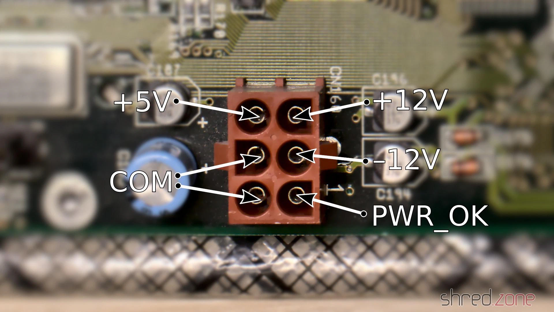
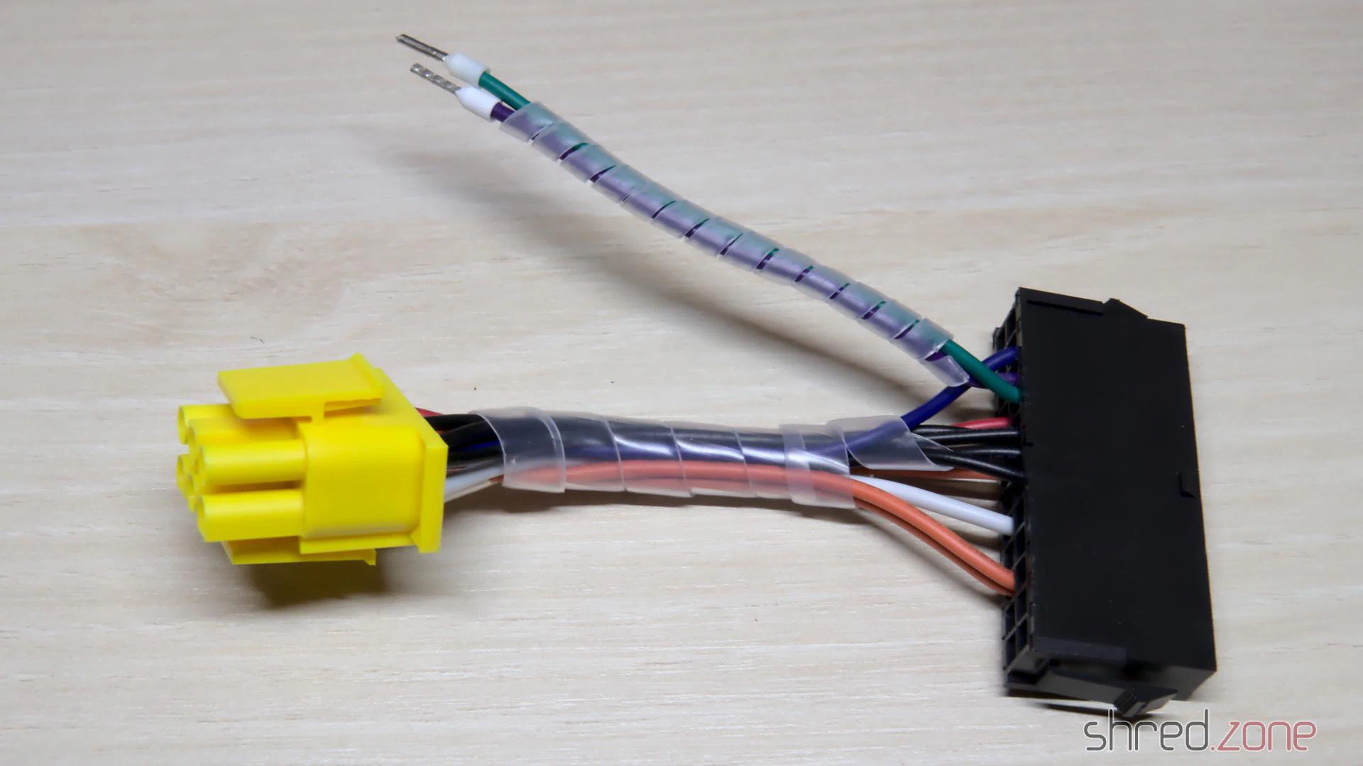
- An ATX to Amiga power adapter. I made one myself using an “ATX to Acer 12-pin” power adapter, a TE Connectivity Mate-N-Lok 6 circuit plug that is still available today, and a crimp tool. Some Amiga shops also sell readily assembled adapters.
To build the power adapter, the wires need to be connected between the Amiga power plug and the corresponding pin of the ATX power connector. The PS_ON# and one of the COM pins are connected to the power switch. All wires should be sufficiently dimensioned.
When everything is assembled, make sure (make double sure, make even triple sure) that the wiring is correct, but do not plug the connector into the mainboard yet. Now press the power button and check the voltages. PWR_OK should have 5V, but it may flutter or even be 0V because the PSU has no load right now. The other voltages must be correct and within a tolerance of 5%. Keep the test short, as it may stress the PSU.
For the first live test, I removed the CPU module, the SIMMs, and all Zorro boards. The Amiga won’t boot like that, of course. But if something should go horribly wrong, the damage would be limited to the mainboard only (which is still bad enough).
Then I turned on the power, for the first time in maybe 20 years. The power LED lighted up. There was no smoke, no smell of burnt electronics, all the chips stayed cool. I checked the power lines, and all voltages were within the expected range. This was looking really good! I turned the power off again.
Now I was confident enough to remount the CPU module and the SIMMs. I also inserted a scandoubler, and connected a monitor to it. Then I turned the system on again. And a few seconds later, I got a picture.
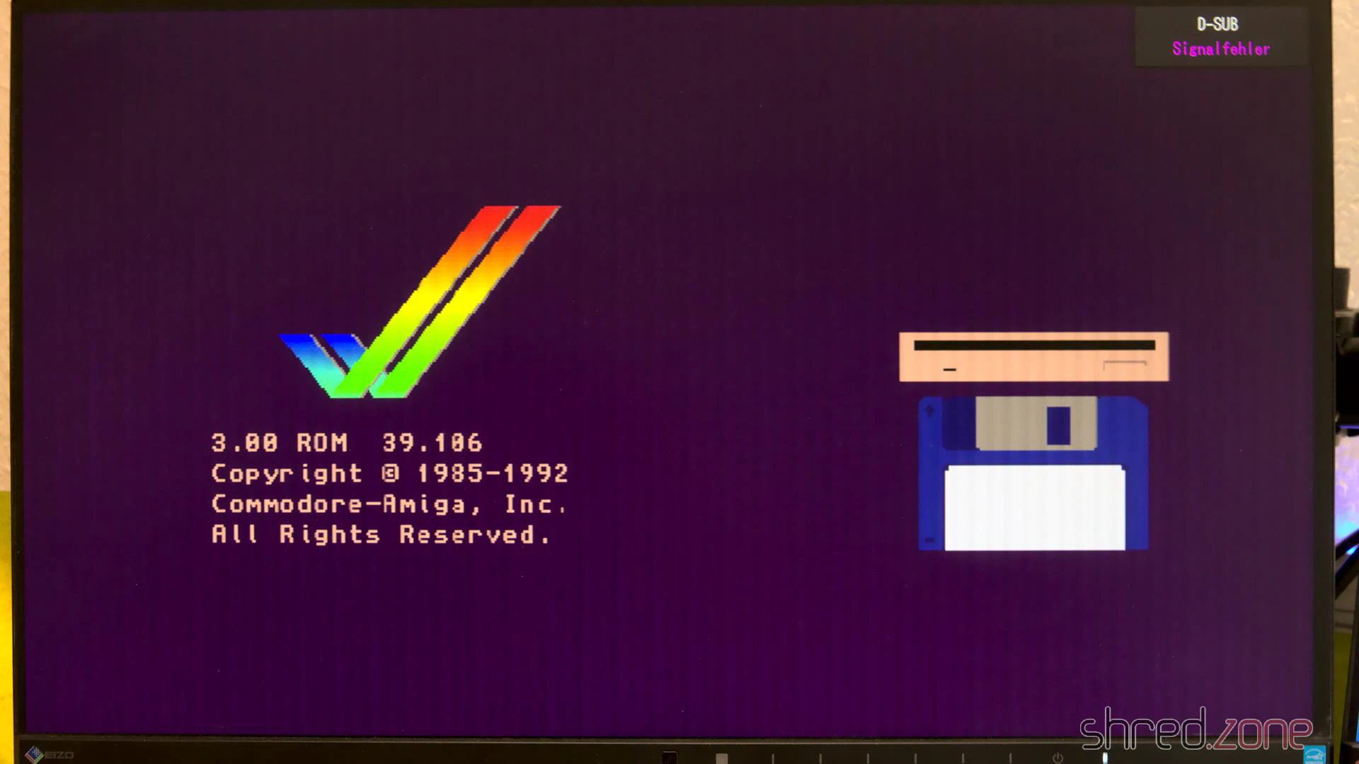
I was probably never that happy to see the Amiga boot screen! 🥲
I had invested some money and many weekends into the refurbishment project, with unknown outcome. All the patience finally paid off.
Reassembly
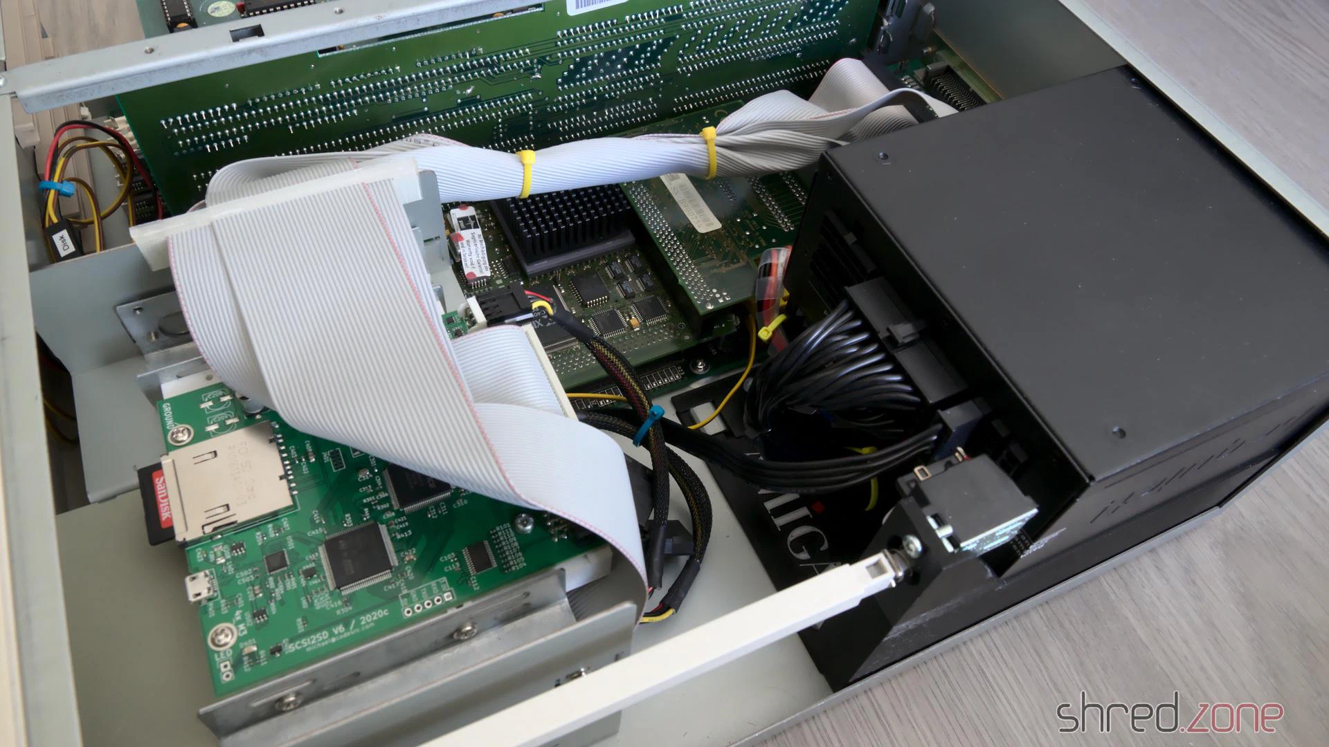
The old mechanical hard disks were loud, slow, and produced a lot of heat. Since I want my Amiga to be as silent (and modern) as possible, I decided to use a SCSI2SD hard drive emulator instead. Alternatively, an IDE to Compact Flash adapter can be connected to the internal IDE header.
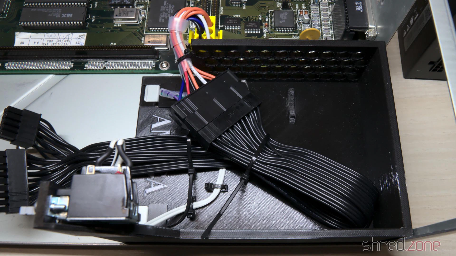
Besides that, I only left a floppy disk drive in the drive cage, but maybe I’m going to replace it with a Gotek floppy drive emulator later. The minimalistic equipment and the modular design of the PSU gives a clean and tidy look on this side of the case. It is also good for the ventilation.
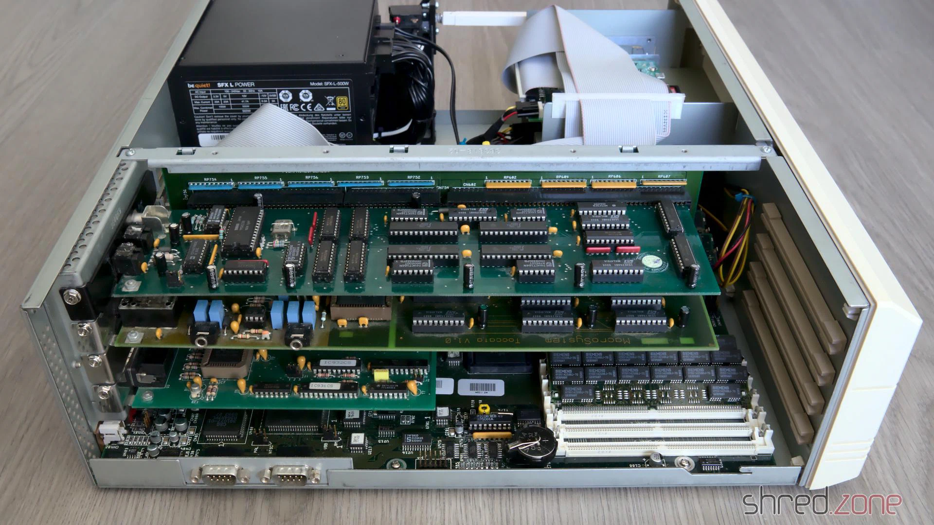
On the other side, the freshly recapped MaestroPro and Toccata sound boards have already moved back to their Zorro slots.
Let’s have a look at the outerior. The CBM Museum Wuppertal did an excellent whitening job again. The keyboard looks as good as new, and the outline of the old sticker on the front is almost invisible now. The paint shop did a good work as well, the cover now looks almost brand new.
I’ve tried to use my original Workbench installation from the 1990s, which I kept on using in an UAE emulator after that, but it was too messed up and crashed the real Amiga while booting. Finally I gave up and installed a fresh Workbench 3.2 from scratch.
What is still missing is a ZZ9000. It will serve mainly as a HDMI graphics card and Ethernet card. After that, my good old Amiga 4000 is ready for some serious Amiga programming again. 😉
Kudos
A refurbishment project like this is not possible without the help of a number of people. First of all, I want to thank the members of the A1K.org Amiga Board, especially halbvier for organizing the rare parts that I needed for the RTC repair. I want to thank the people of the CBM Museum Wuppertal for carefully whitening the plastic parts, and for the nice talk we had. I also want to thank Jan Beta because his YouTube channel inspired me to refurbish my two Amigas.
This project is dedicated to my brother Robert, who had taught me how to solder and how to repair old hardware. I miss you.
More like that?
Read about LinuxJedi’s double A4000 restoration.
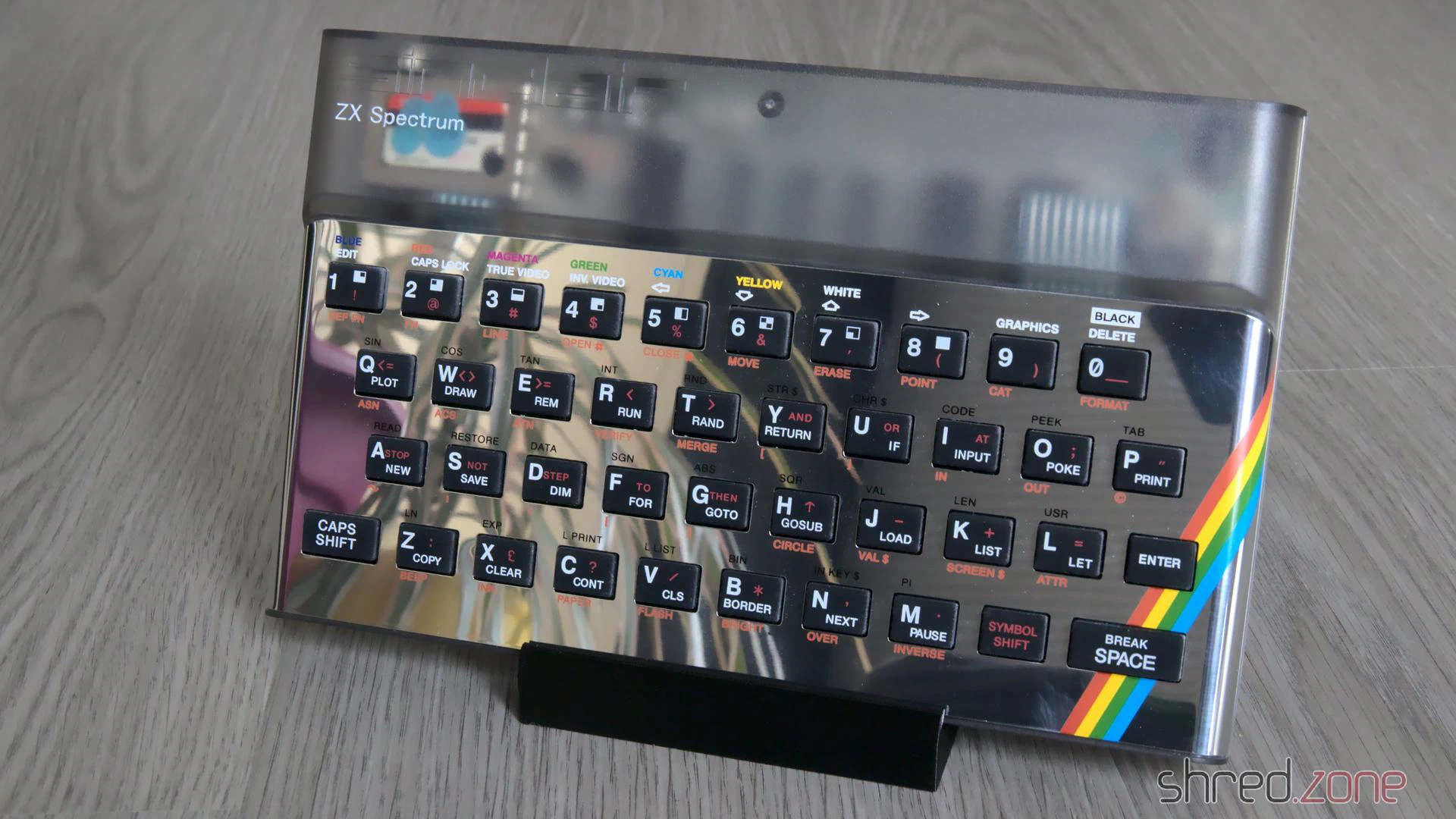
I still own two ZX Spectrum 48K from my very early days of home computing. The first is my own one, I got it from my parents as a Christmas present back in 1985. The other one was owned by a friend. It was broken and couldn’t be repaired, so he first intended to throw it away, but then gave it to me instead.
So here are the two sisters…
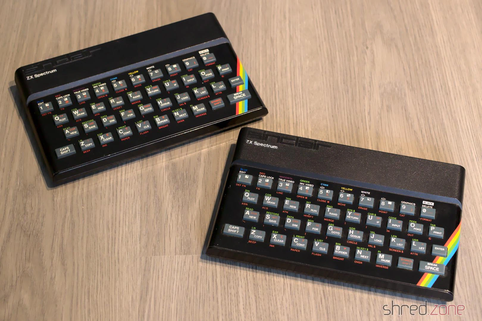
This article is about the restauration of my own ZX Spectrum. There will be a follow-up for the other one.
Let’s have a look under the hood. This Speccy has a standard Issue Two board, with a floating transistor on the CPU as an usual factory modification of that board.
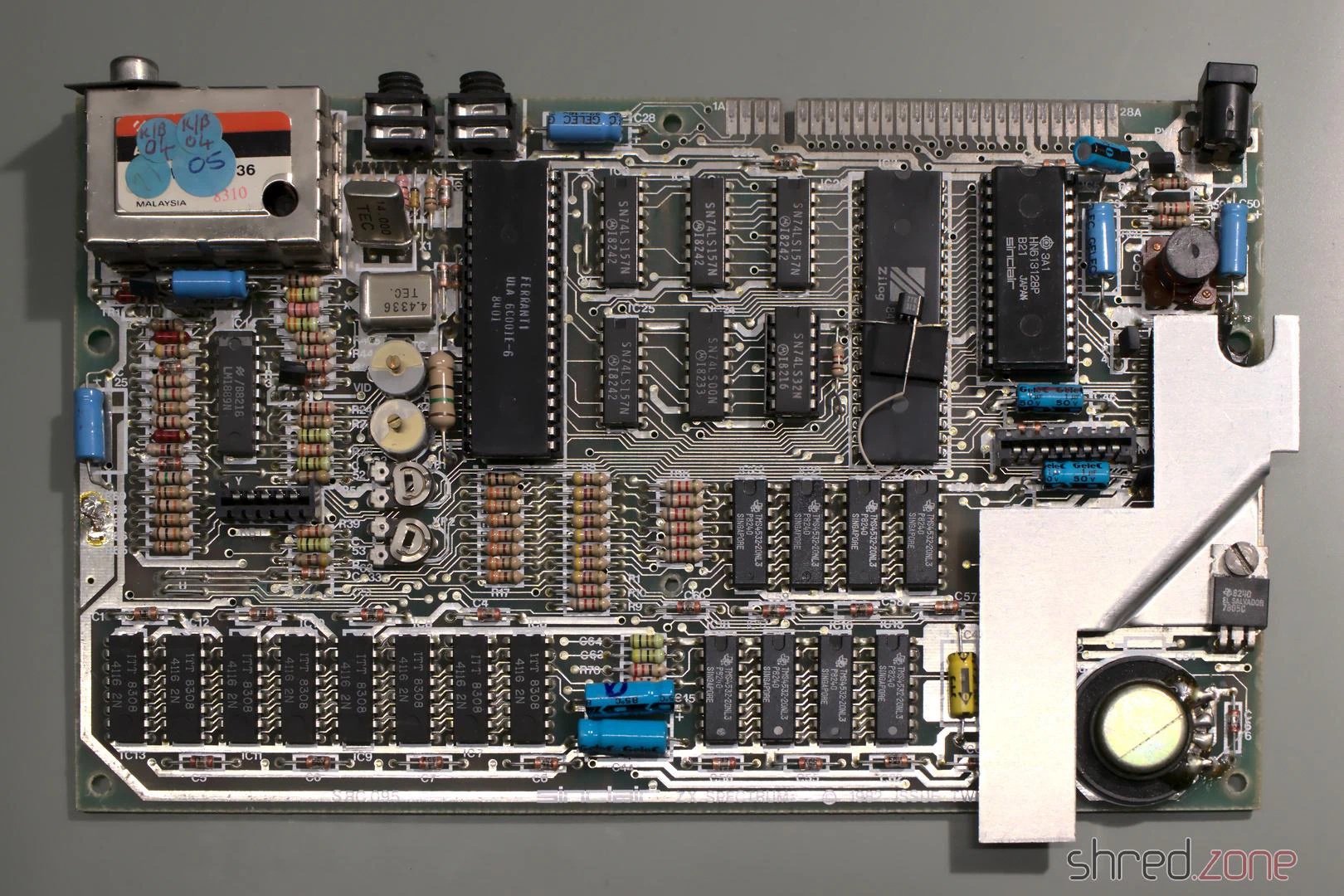
It looks alright so far. Let’s find out if it is still working.
Composite Mod
All home computers of that era were designed to be connected to the “antenna in” of an ordinary color TV. The TV was tuned to UHF channel 36 to receive the signal. The picture quality was quite okay back in those days, but poor for today’s standards.
Today, almost all TVs have a composite input, so there is no need for modulating the signal any more. Luckily the ZX Spectrum can be easily modified to give a composite signal. First, the two existing wires on the side of the TV modulator are unsoldered and just bent to the side (so the mod can be reversed if desired). Inside the modulator, the resistor is disconnected from the RCA jack. Then a new wire is connected from the outside’s former signal pad straight to the RCA jack.
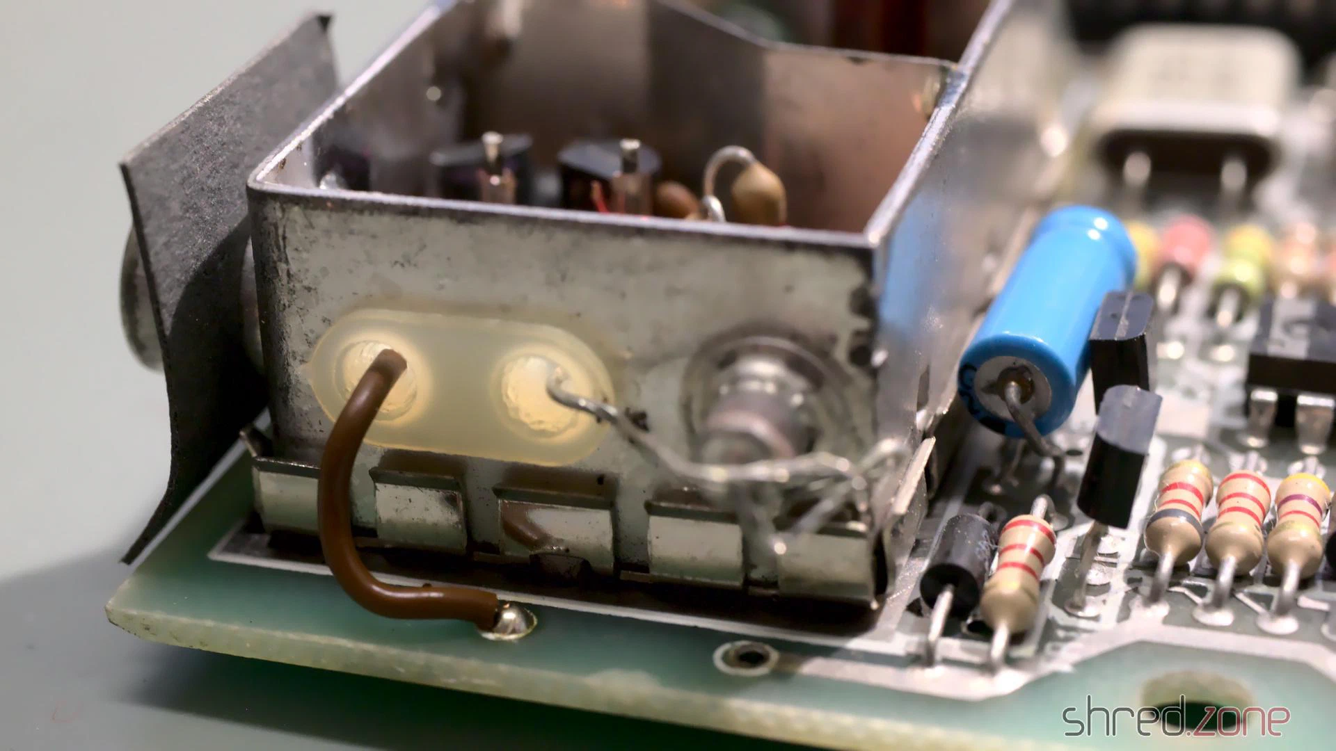
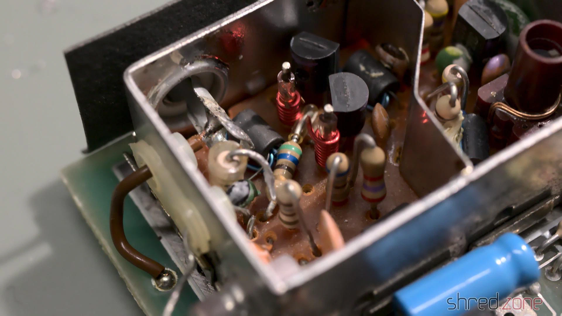
After that modification, the Spectrum can be directly connected to the TV’s “composite in”. The modification can be easily reverted, and there is no need to drill an additional hole into the case.
Testing
I have lost the original ZX Spectrum PSUs, but any stabilized 9 V PSU with at least 1.5 A will do as a replacement. It is very important to check the polarity of the barrel plug! Most modern PSUs have the positive pole at the inside of the plug, while the ZX Spectrum expects the positive pole at the outside:
Many Speccys certainly have been killed by using a replacement PSU with the wrong polarity.
I powered it up, and to my surprise it was still working!
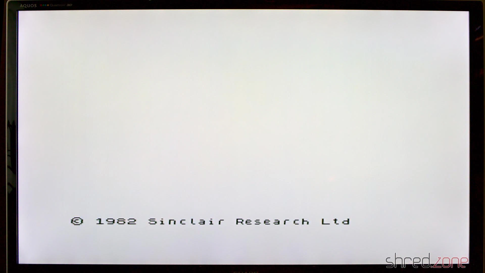
All I would need to do now is giving it the usual technical overhaul.
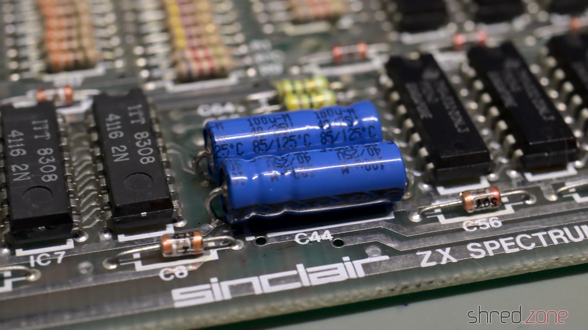
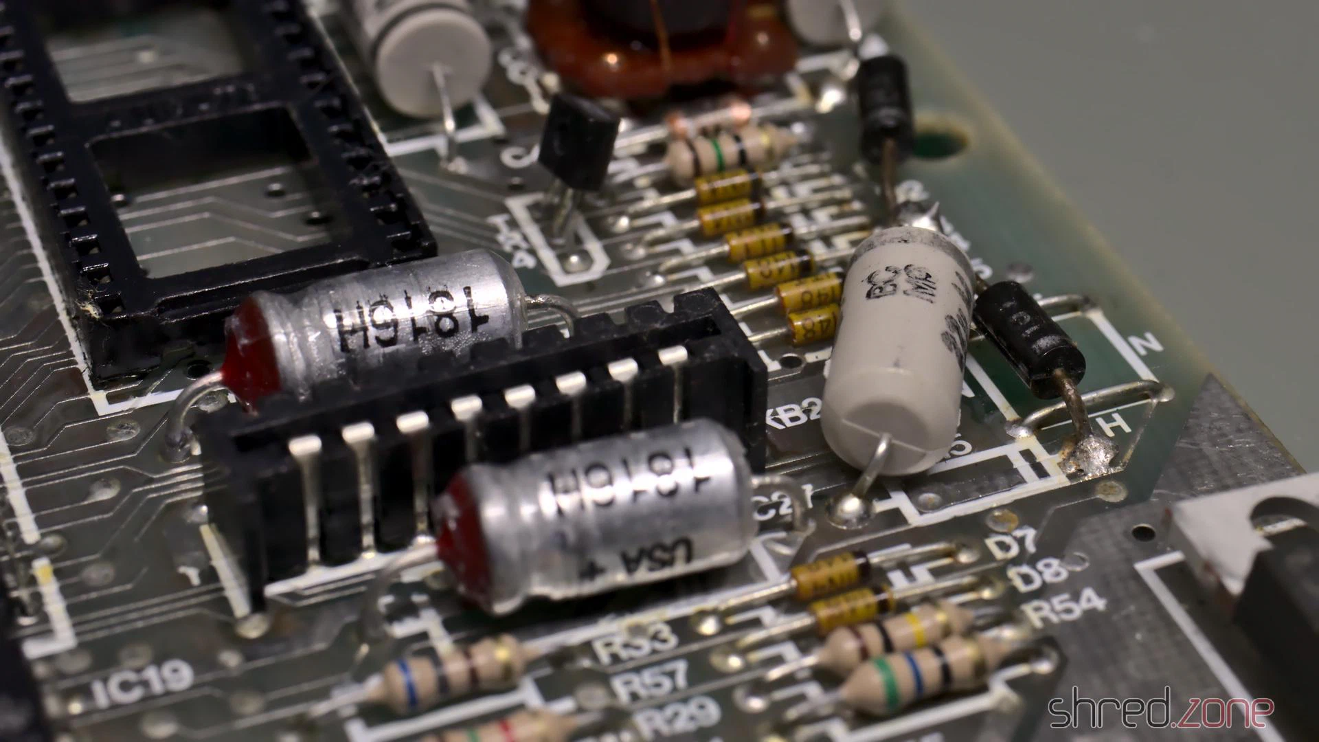
Recapping
The first thing is to replace the electrolytic capacitors. The old ones dry out over the years, and lose their capacity. Some may even leak and damage the PCB.
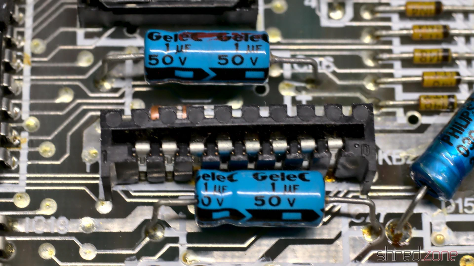
To keep the old look, many people prefer axial caps with the classic shape and a blue (or at least black) color.
High quality axial caps are difficult to find and quite expensive. I chose to use Vishay capacitors with an expected lifetime of 2,000 h. However the reference photos of the retailer deceived me. The nice black “classic” caps turned out to have an odd shape, and an aluminum or plastic grey color. They are not of an inferior quality, quite the contrary, but they just don’t look vintage. I still decided to use them.
There is a trap on the Issue 2 boards: the polarity of C46 is indicated backwards on the silkscreen. The capacitor must be installed with the positive end to the left.
After the recapping, I thoroughly washed the board with IPA and a toothbrush. Then it was time for another test.
Operation Successful…
…but the patient died. This is what I saw when I powered it up again:
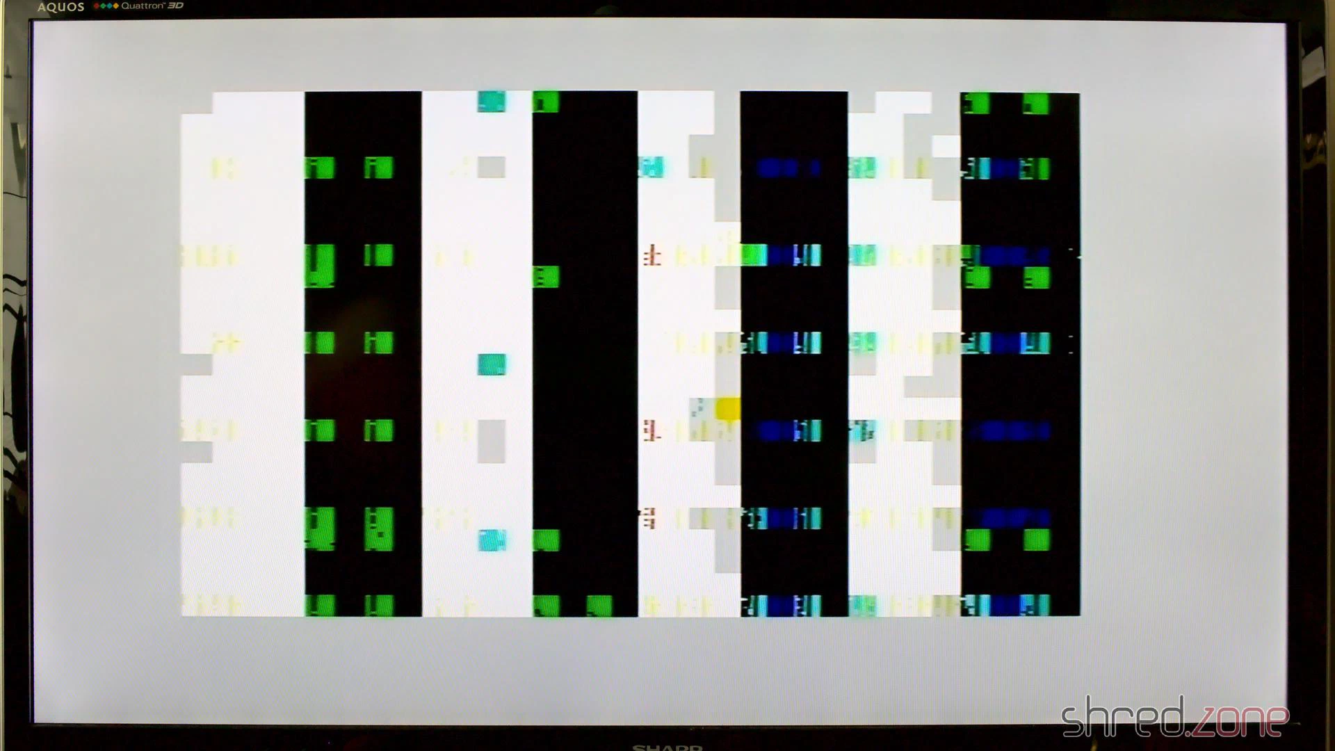
Obviously I broke something. 😯 But what?
I first checked the voltages, but they were all right. No chip was getting hot, except of the ULA, but that’s normal.
The ROM chip is socketed, so I removed it. Without the ROM, the CPU always executes the same instruction (RST 38h), which fills the memory and results in a distinct screen pattern.
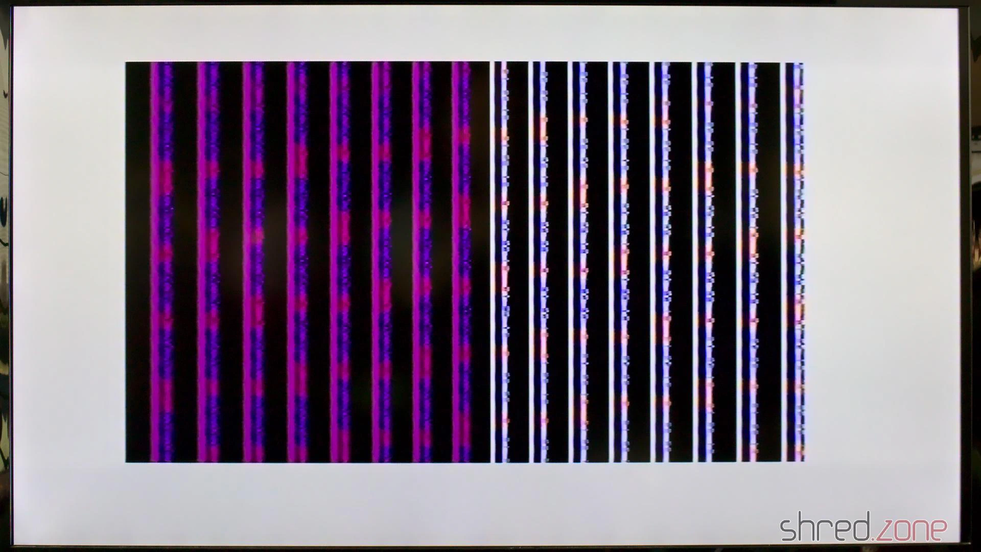
The pattern was there, so the CPU was fine, but it had some noise in it. I suspected a broken RAM chip, and the signal on the data bus actually looked a bit strange on the scope. I started to replace a few suspicious RAM chips, but to make a long story short, it didn’t change anything. I was clearly on the wrong track.
I tested the ROM, but it was fine. I swapped the ULA with the one from the other Speccy, but it didn’t help either. I checked all the capacitors I had replaced, but they had the correct values and orientation, even that infamous C46.
What has just happened that damaged a previously working Spectrum so badly?
I noticed that, as the only standard chip, IC23 was socketed on that machine. It must have been from a previous repair, because unlike all the other soldering joints, the lead was yellowish there. When I touched the joints with the tip of my soldering iron, they were also sizzling. This was just scrap. I completely removed the old lead, and soldered in a new socket.
Could this have been the problem? I gave power to the Speccy. And yes, it was working again! 😄
I guess that when I cleaned the board with IPA, I partially dissolved the flux in these old soldering joints, making them cold. IC23 is used for the proper access timing of the upper RAM. With a bad timing, the upper RAM might just have disturbed the entire data bus.
Finishing Works
With the Speccy brought back to live, I did some final cleanups.
A defective TR4 is a common cause for a broken power converter. It was still working here, but I precautionary replaced it with a ZTX651, which is the more reliable successor type.
I also preemptively replaced the 7805 voltage regulator by a fresh one, and used thermal paste for better cooling. It’s common in the retro scene to replace the 7805 with a modern step-down converter that does not need any cooling, but I decided against it. I like to feel the heat of a working ZX Spectrum.
The ribbons of the keyboard membrane got brittle over the years, and already started to break. Luckily there are new membranes available on the market. And since I was on it, I also ordered a transparent replica case, a black rubber keyboard mat, and a chrome faceplate. I especially like the idea of a transparent case making the inside of this old computer visible.
The first of both sisters is restored now. The other one might be more difficult to restore though, as it was said to be “broken beyond repair”. Let’s find out.
Addendum
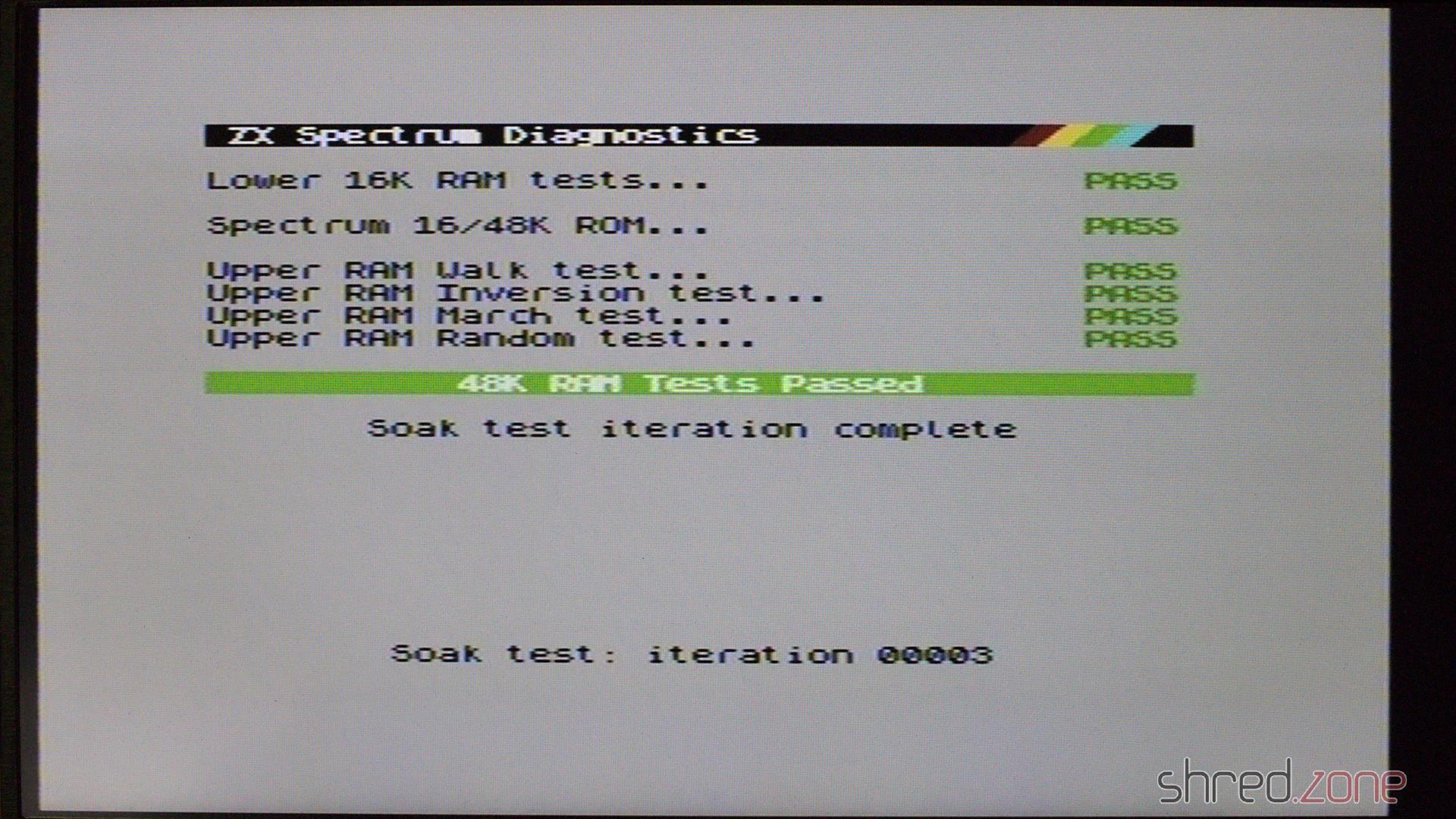
Never claim a repair is done before you ran some diagnostics. Some months later, I tested this Speccy with a Diag ROM and found that three upper RAM chips are defective.
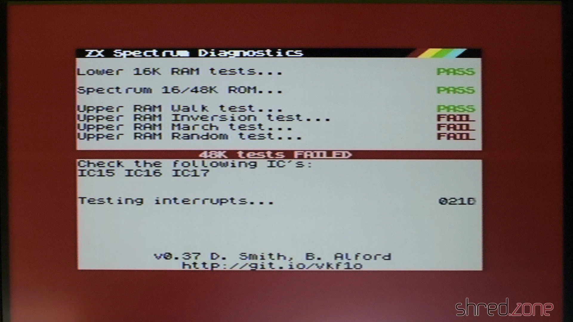
Fortunately the Diag ROM gives exact advice about what RAM chips need replacement. It was also fortunate that I had a sufficient number of spare chips on stock.
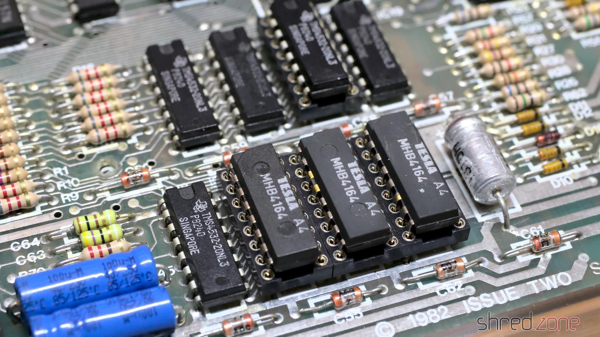
The advantage of the MHB6164 chips I used is that they are true 64KBit RAMs, so I don’t need to take care that they match the other TMS4532 RAM types. After replacement, all diagnostic checks were finally green.