In the first part, I repaired the motherboard of an Amiga CD³² that was damaged by leaking capacitors and a botched restoration attempt. In this part, I am now replacing the laser unit and calibrating the CD drive.
The old laser unit in most CD³²s is likely worn out due to age and use. A common symptom is that the CD³² no longer plays CD-R media or only recognises music CDs. Incidentally, the CD³² generally does not recognise CD-RW media, as these use a dye instead of pits, which reflects too little light. This cannot be fixed even with a new laser unit.
Before we start, a heads-up:
WARNING: The laser unit is very sensitive to electrostatic discharge. Always take protective measures, e.g. by wearing an antistatic wrist strap.
Ensure that the laser is always covered when the computer is switched on (e.g. with a CD or a piece of paper). Do not look into the laser beam.
I would also like to mention at this point that I am not a trained technician. I have read guides on calibrating CD drives, and it worked for me. However, I do not claim that this is the best or most professional way to perform a calibration.
To replace the pick-up, a soldering iron and definitely an oscilloscope for the subsequent calibration are required. It might be possible without calibration, but the result will not be optimal.
Replacing the laser unit
First, I removed the CD drive from the case. Then I carefully separated the mechanical unit from the controller, and removed the four screws holding the frame of the mechanical unit. The metal shielding covering the pick-up must also be removed.
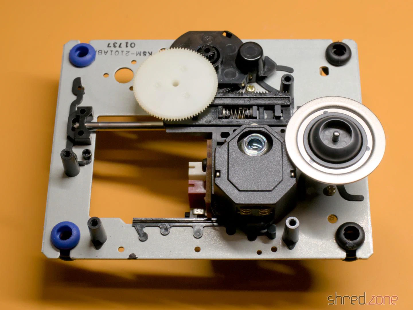
The pick-up is a Sony KSS210A. It is out of production for a long time, but replicas are offered on online marketplaces for a few euros. To remove the old unit, I first took off the white cog and then pulled out the metal rod (it is only held by a plastic clip that can be pushed to the side). While I was at it, I removed the old grease from the rod and the cogs, and then applied a little silicone grease. After that, I mounted the new unit and reassembled the CD drive in reverse order.
Important: Immediately after the new laser unit is connected to the controller, a solder blob on the laser unit must be removed! It protects the laser from static electricity, but would irreparably damage the drive controller if it is still present when switched on.
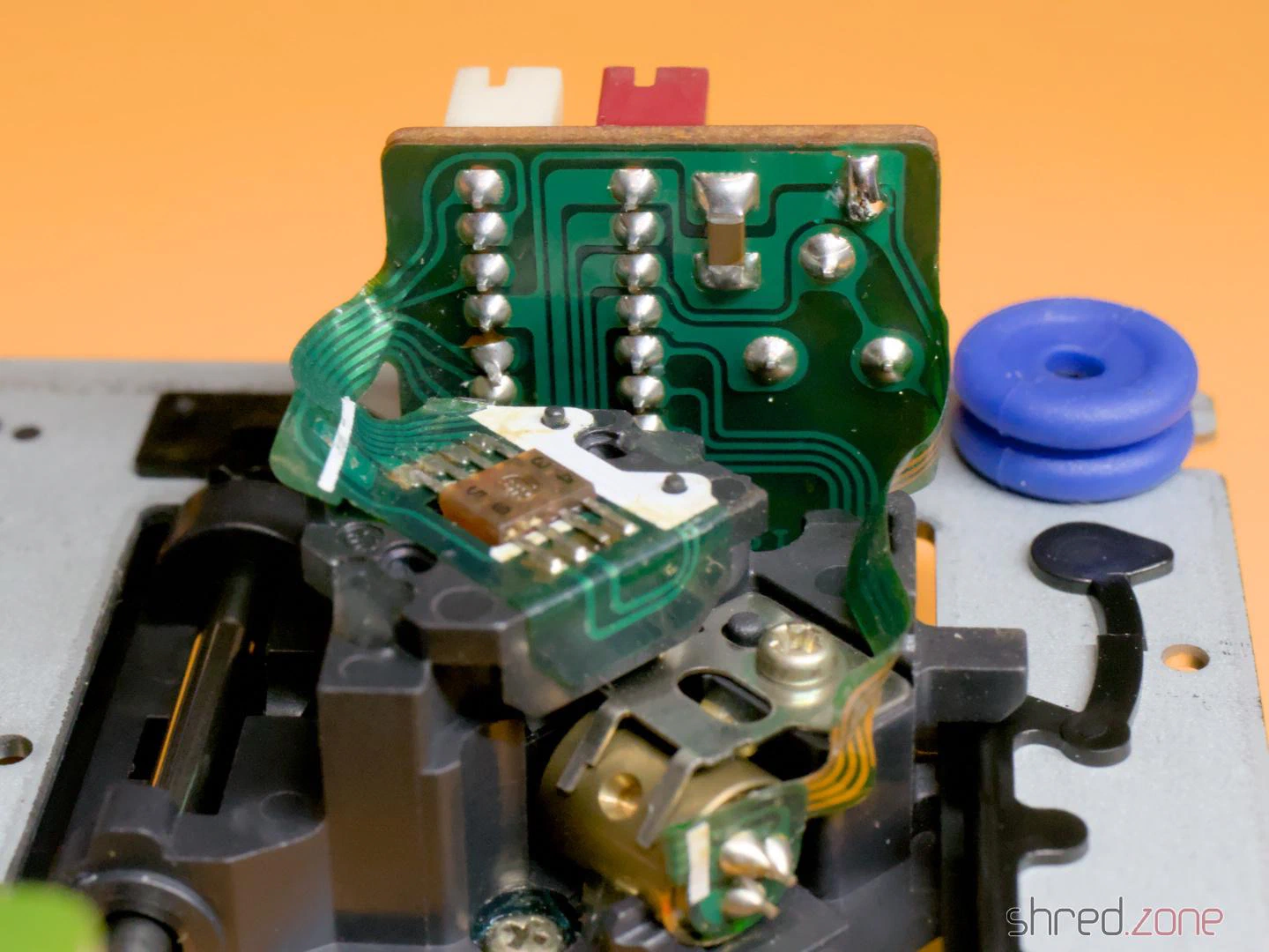
If you want to keep the original laser module, you should also apply a solder blob there before disconnecting it.
Preparation
I removed the metal shielding of the drive controller to perform the calibration. There I found a surprise: a tiny circuit board glued to the motherboard and connected with seven wires.
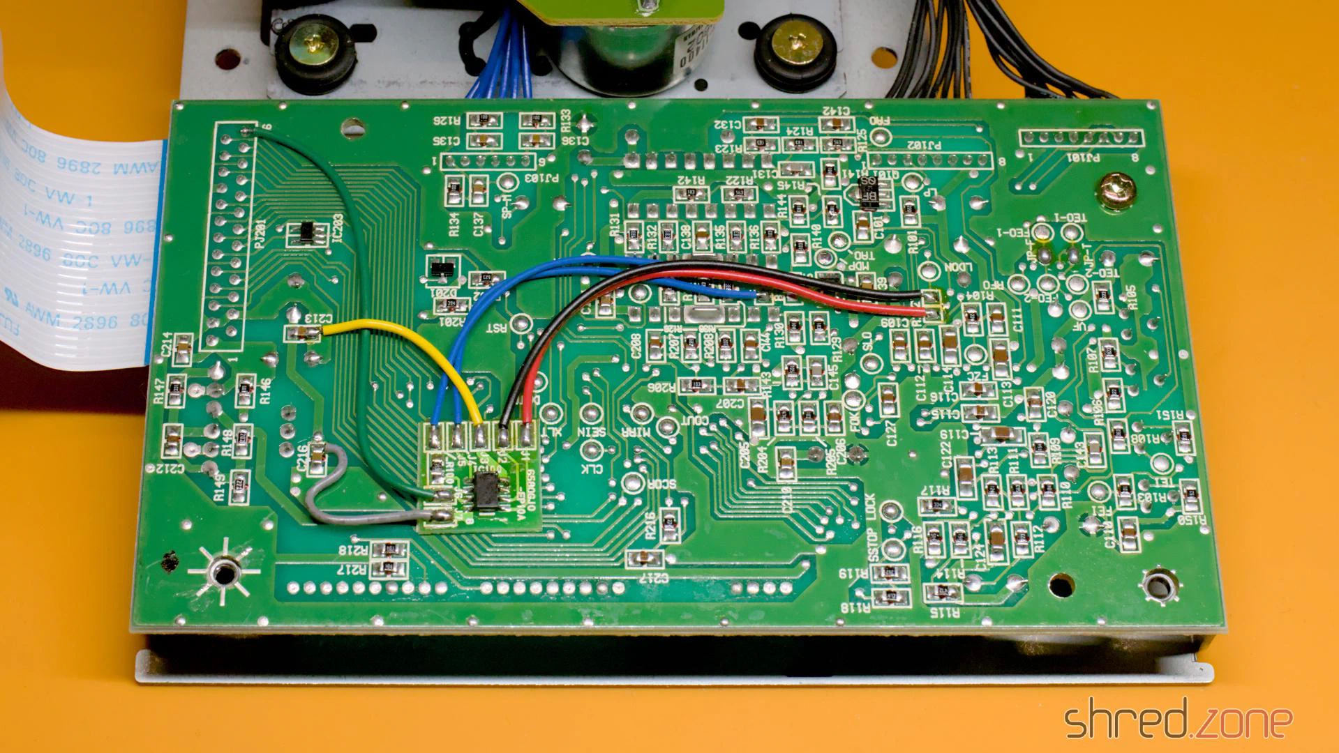
At first I assumed this might be a mod to bypass copy protection measures. However, the CD³² didn’t have a sophisticated copy protection system to bypass. Later I found the answer in a YouTube video: This modification cuts the power supply to the laser and the spindle motor as soon as the lid of the CD drive is opened. However, I could also find many photos of the controller board without the modification. I assume it was a product safety requirement so the CD³² could be sold on the German or European market.
Okay, back to the calibration. As a preparation, I soldered wires to the test points VF, RFO, TEO-1 and FEO-1. I recommend using different colours for this, it makes the calibration easier. Unfortunately, I only had red wire at hand, so I had to check every time which wire went where.
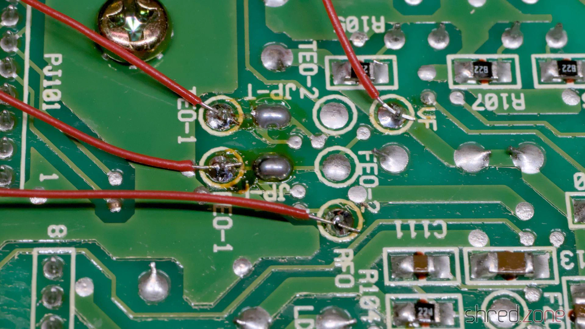
After that, I measured the current settings of the four potentiometers on the controller board and the potentiometer on the laser module with an ohmmeter, and wrote them down. If the calibration should go wrong for any reason, I could restore these settings at any time. A photo of the potentiometer positions would be far too inaccurate, by the way, better to measure!
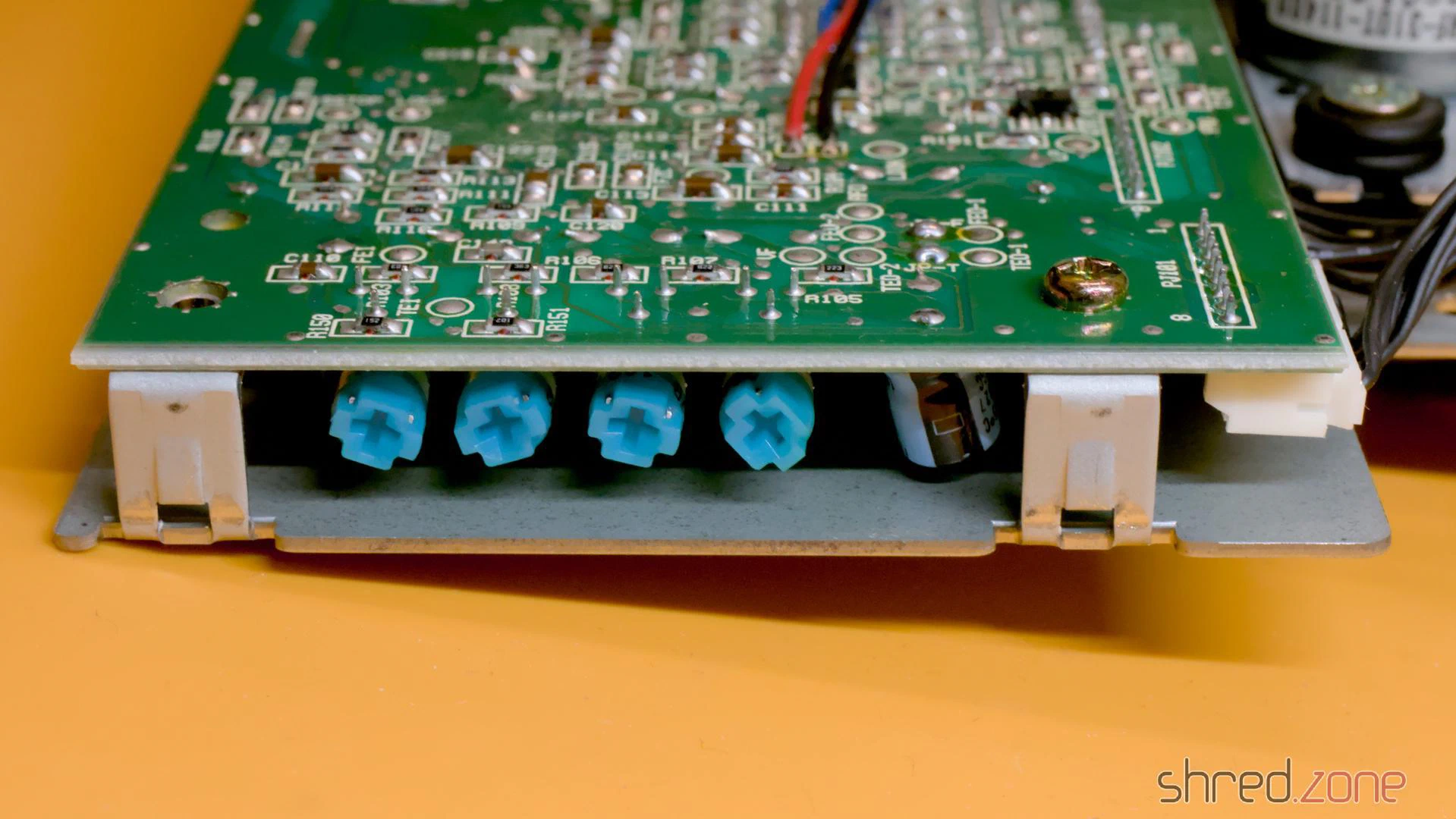
For the calibration, the drive must be reconnected to the motherboard. The top of the case (with the LEDs, the reset button, etc.) must also be connected, as the CD³² does nothing as long as the drive lid is open. The laser unit moves during operation and should have enough space for this.
To hold the CD on the spindle, I removed the spindle clamp from the inside of the lid and fixed the loose part in the middle with a little sticky tape. A magnet holds the clamp to the spindle and ensures that the CD does not slip.
Calibration
The actual calibration process is explained in this blog article by TSB. My attempts to explain it would be far worse. 😉
It turned out with my drive that the process didn’t work like that. After I had carried out the first steps of the calibration, the drive suddenly went on strike and didn’t read anything at all. Fortunately, I had noted down the potentiometer positions, so I could restore the original settings and start over.
Afterwards, I first calibrated the TEB pot until there were about 0 mV between TEO-1 and VF. The drive was still running after that. Only when I calibrated FEB as documented did it strike again. I undid this change and continued with the calibration of the laser power.
WARNING: Be extremely careful with the potentiometer on the laser module and only turn it in very small steps. Otherwise, the laser can be permanently damaged.
There may be a drop of varnish on the pot. It is advisable to turn the pot first while it is switched off to break the varnish, and then use the ohmmeter to reset it to the noted factory setting.
To calibrate the laser power, I connected the oscilloscope to RFO and ground. Then I put a music CD on the spindle and started track 1. The oscilloscope should now show a so-called “eye pattern”:
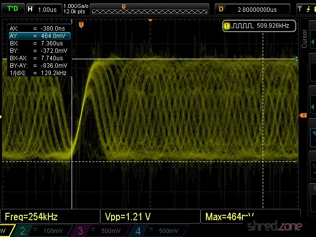
The tricky part is to adjust the pot on the laser module while the CD is playing. I adjusted it very carefully until I reached a peak-to-peak voltage of about 900 mV. 1200 mV should never be exceeded.
Then I adjusted the FEB pot on the controller board until I reached a maximum amplitude in the eye pattern.
The last two pots, FEG and TEG, are calibrated by measuring the test points FEO-1 and TEO-1 respectively against ground. The drive should be playing track 1 of an audio CD and be in pause mode during calibration.
I tried to find the ideal point where the signal on the oscilloscope is as smooth as possible and the correction noises of the laser optics are as quiet as possible. The goal is to find the best possible compromise. You will probably get the best results if you listen to the noises of the laser unit and follow your gut feeling.
The calibration is then complete and the CD³² can be reassembled.
Tip: Burn CD-Rs for the CD³² at the lowest speed your burner supports. This increases the contrast of the data on the CD. Also, prefer CD-Rs that are not transparent when held up to the light.
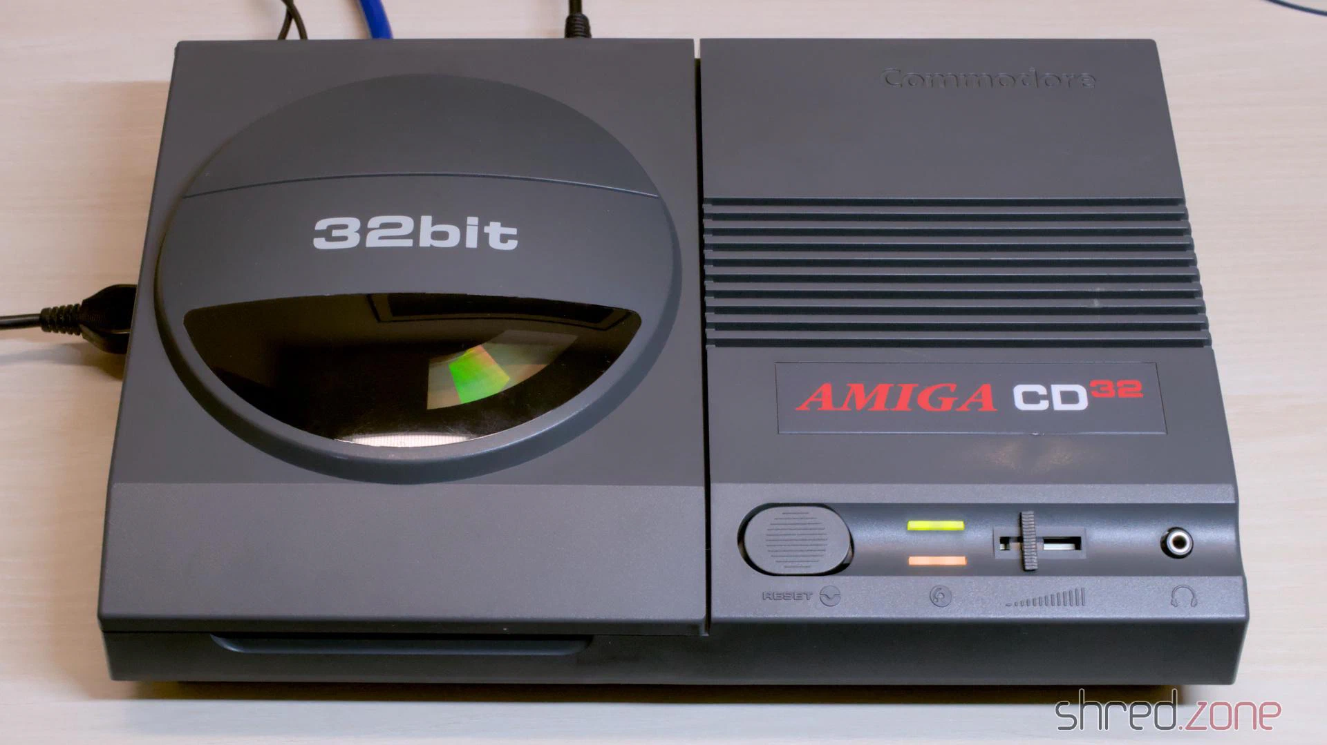
I found this CD³² at a fair price. The machine is still missing from my collection, so I grabbed it. The visual condition of the casing is quite good. There are a few visible scratches. The previous owner tried to touch them up, but only made it worse. At the time, I didn’t suspect that this would be the main theme of the entire restoration.
Together with the games console, I received a power supply and a maths edutainment CD. The power supply wasn’t original, but rather a typical “brick” for external hard drives with a soldered-on CD³² plug. Unfortunately, the gamepad was missing, but luckily I found a practically mint condition Honey Bee Joypad as a replacement a bit later.
Let’s take a look inside.
The Condition
The Amiga was sold as defective because it didn’t display a picture.
The circuit board told me a completely different story. An attempt had already been made to replace the capacitors. After replacing the TH and 100µF SMD capacitors, the attempt was abandoned. Presumably because the picture was gone after that.
I also found several green varnish spots, probably simple nail varnish. It was underneath the replaced SMD capacitors, on solder joints as well as some vias. The varnish made cosmetic sense at best in those places.
And then I found this:
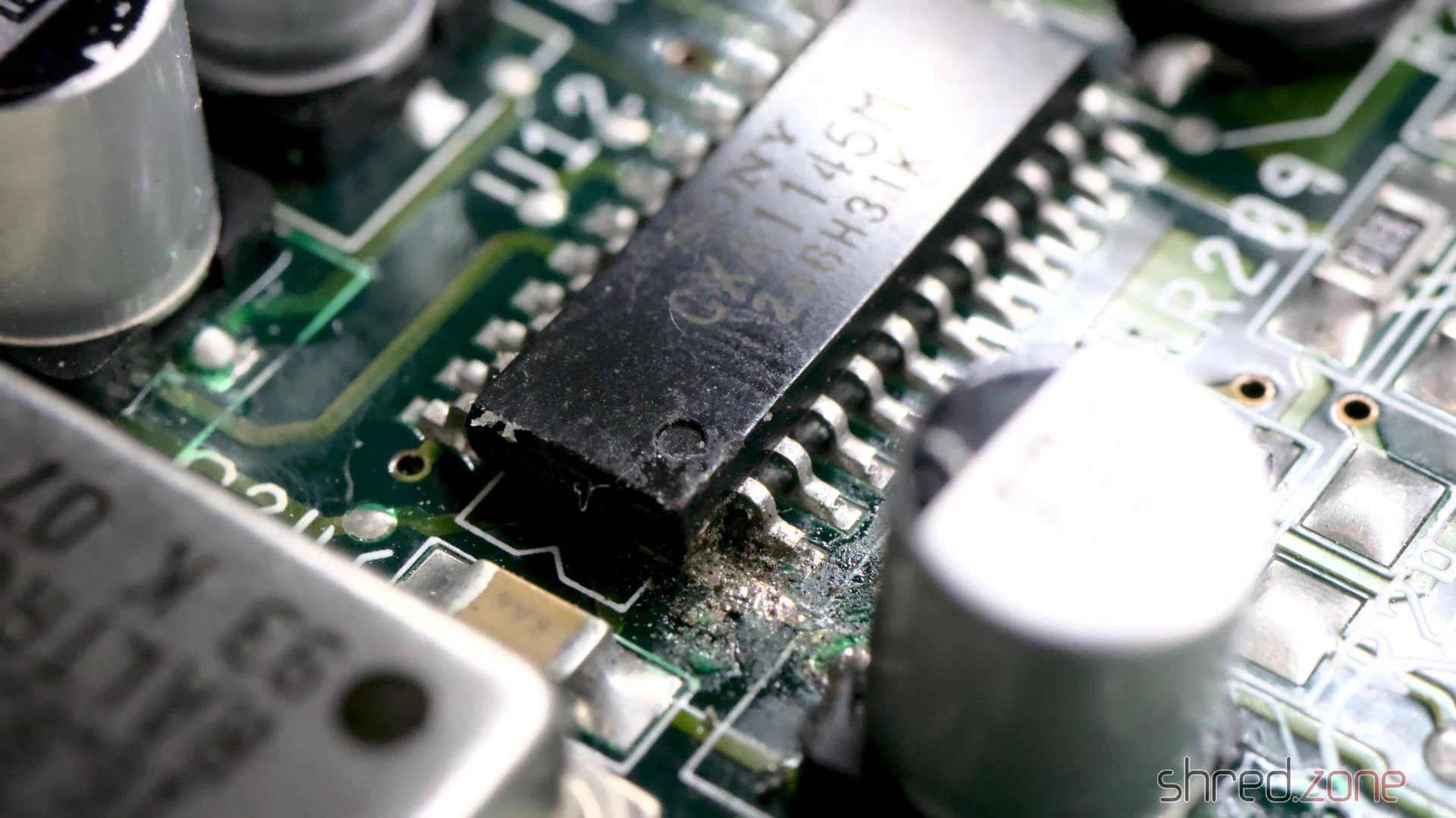
I can only speculate at this point: When the picture suddenly disappeared in the middle of recapping, the previous owner assumed that the video encoder chip was damaged. An SMD chip can only be removed with a hot air rework station, which they probably didn’t have available. So instead they tried to cut the chip off the board leg by leg. Fortunately, they aborted the attempt after just one leg.
Luckily, I didn’t find any further traces of “abuse” on the poor board. It will be enough work as it is to clean up the existing mess.
To be honest, I’m quite annoyed about it. It makes a difference whether the machine simply stops displaying a picture after decades in the cellar, or because someone botched around on the circuit board. The seller should have pointed this out, naturally with corresponding negative effects on the price.
Repair of the Mainboard
At this point it made the most sense for me to restore the picture first. So I replaced the video encoder, as well as an already replaced electrolytic capacitor right next to it that looked suspicious. With that, all visible defects were eliminated. Unfortunately, it didn’t bring the video signal back.
Why did the picture stay black? Were there other faults in the video section, or did the machine possibly not boot up at all?
To find out, I inserted a DiagROM and connected the CD³² to my PC. The DiagROM booted without any problems and logged no errors on the console. Good news: The problem had to lie solely in the video section.
So it was time to tidy up. I removed all electrolytic capacitors, including the ones that had already been replaced. After that, the green nail varnish came off, with nail varnish remover and isopropanol.
On the underside I found a strange solder lump covered by a thick layer of varnish. When I tried to remove it, a telltale fishy smell of leaked electrolyte wafted up. Not a good sign. It meant that a capacitor had leaked and the area wasn’t properly cleaned. I generously removed the SMD parts on both sides in this area, cleaned the board thoroughly and checked the tracks and vias.
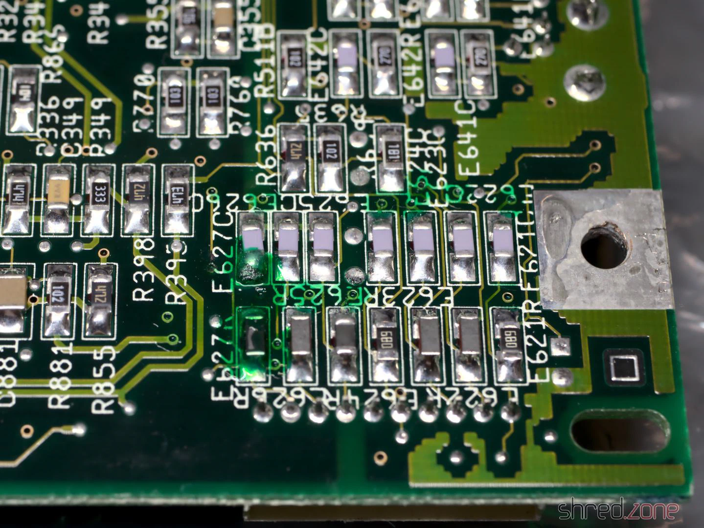
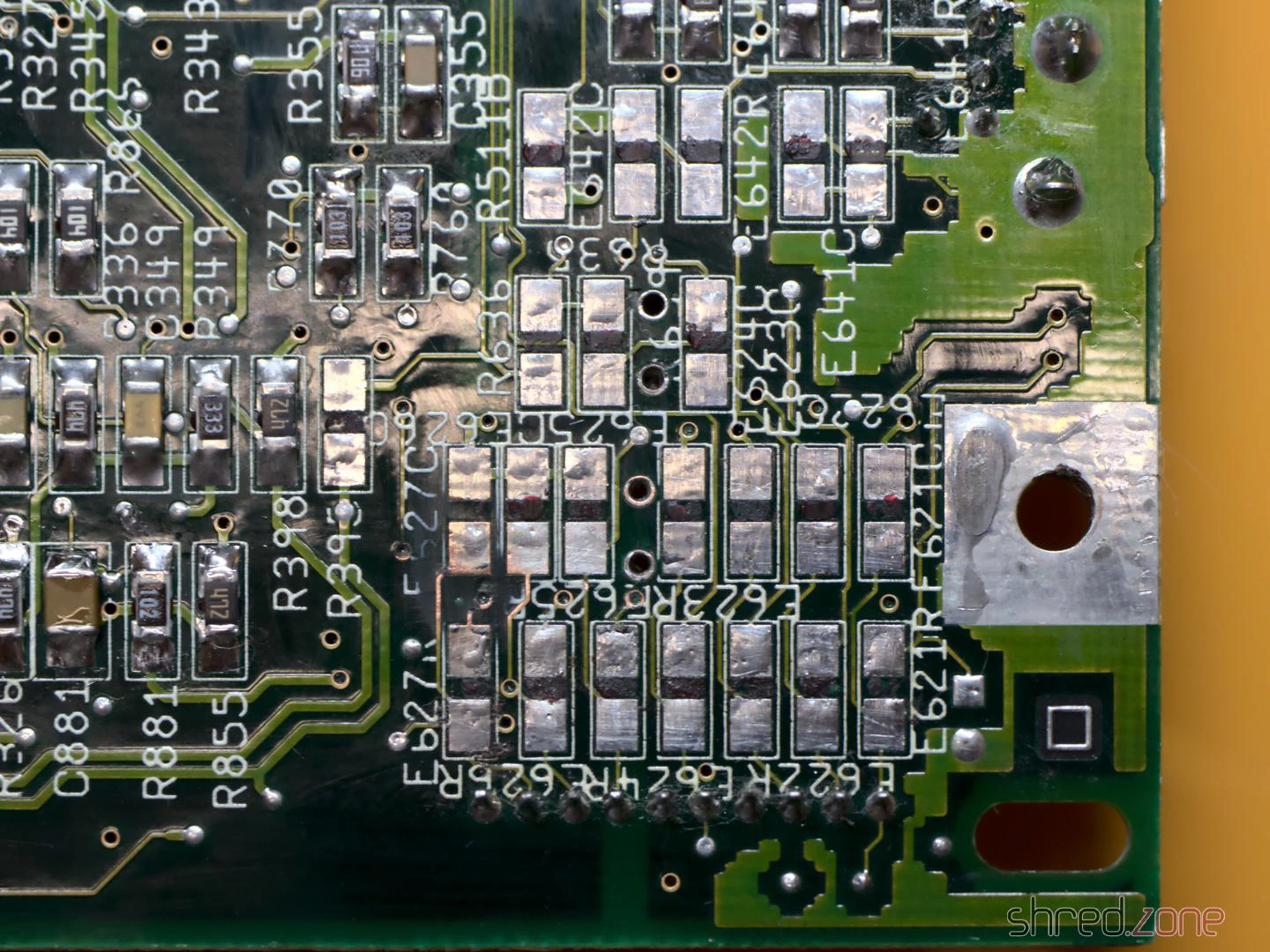
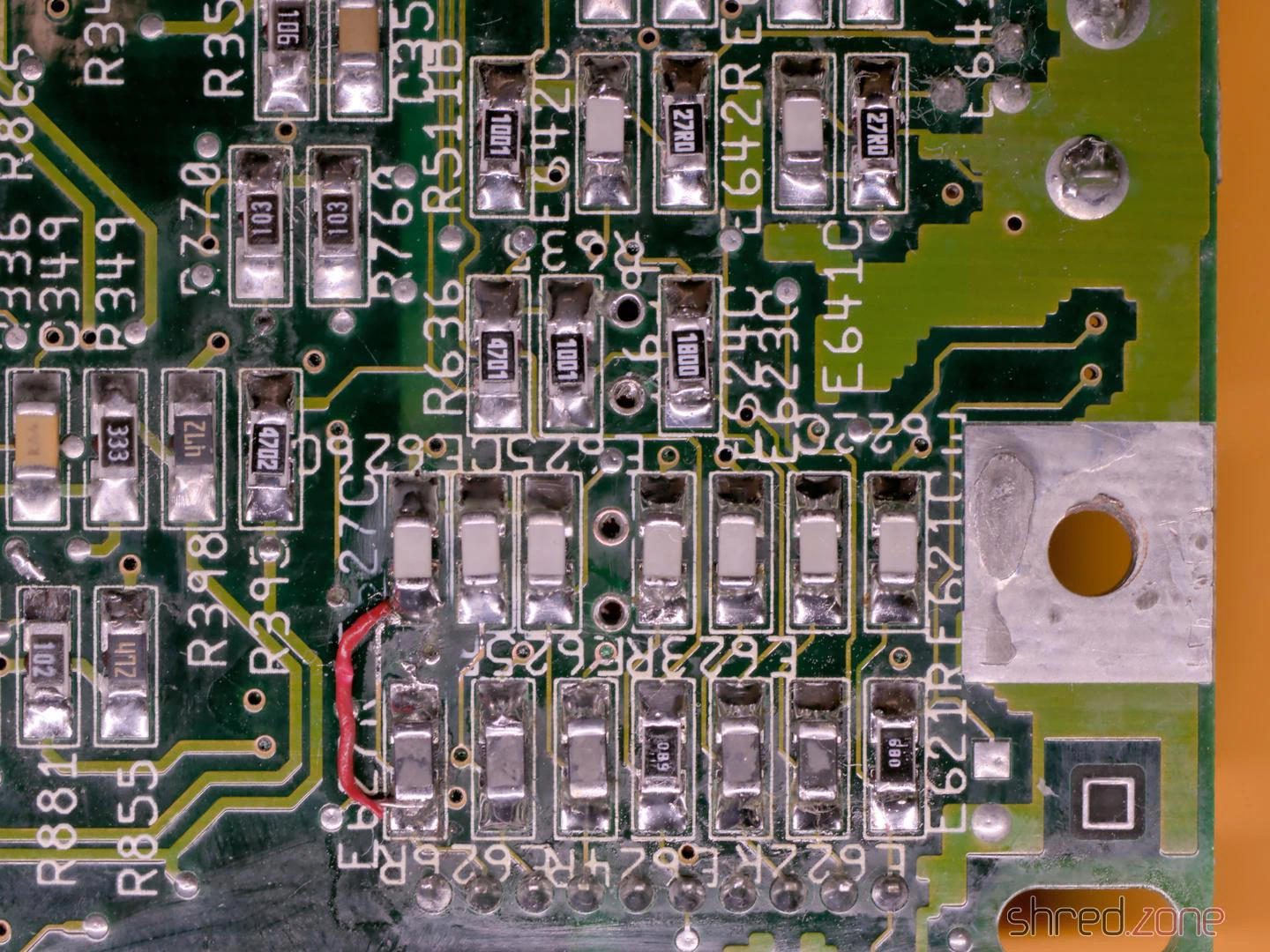
Unfortunately, I tore off a few pads on the 100µF capacitors in the process. I suspect the leaked electrolyte and the thermal stress of two recappings were simply too much for them. Something like this is annoying, but not the end of the world.
Afterwards, I soldered in new components and repaired the torn-off pads with bodge wire. For two SMD capacitors, the board alternatively offered the use of TH capacitors, which suited me very well. Visually, this corner doesn’t look like much anymore, but it should work again.
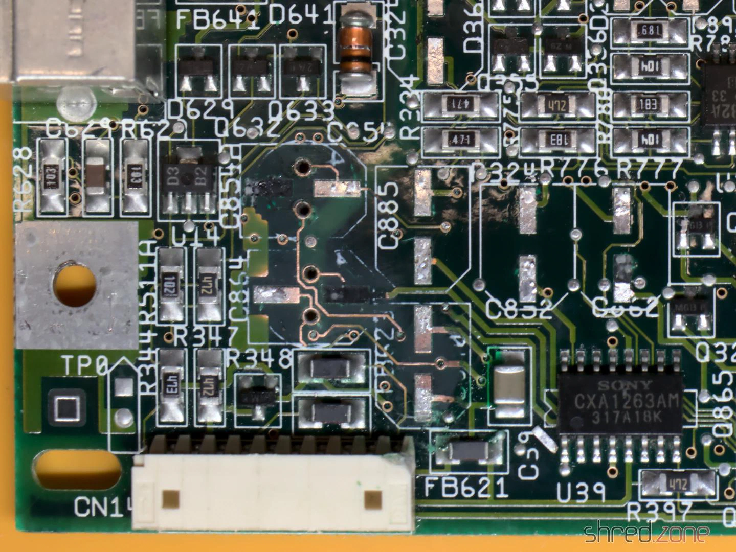
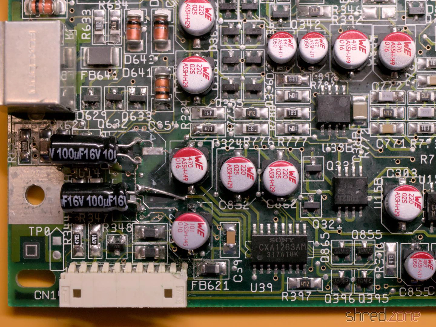
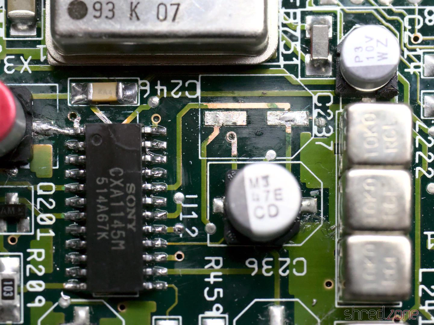
When I buzzed out the tracks and vias on the other 100µF SMD capacitors, I found further breaks at C236 and C237. They carry the luma and composite video signals and would be an explanation for why the picture stays black.
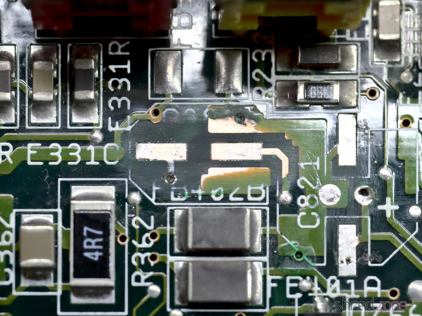
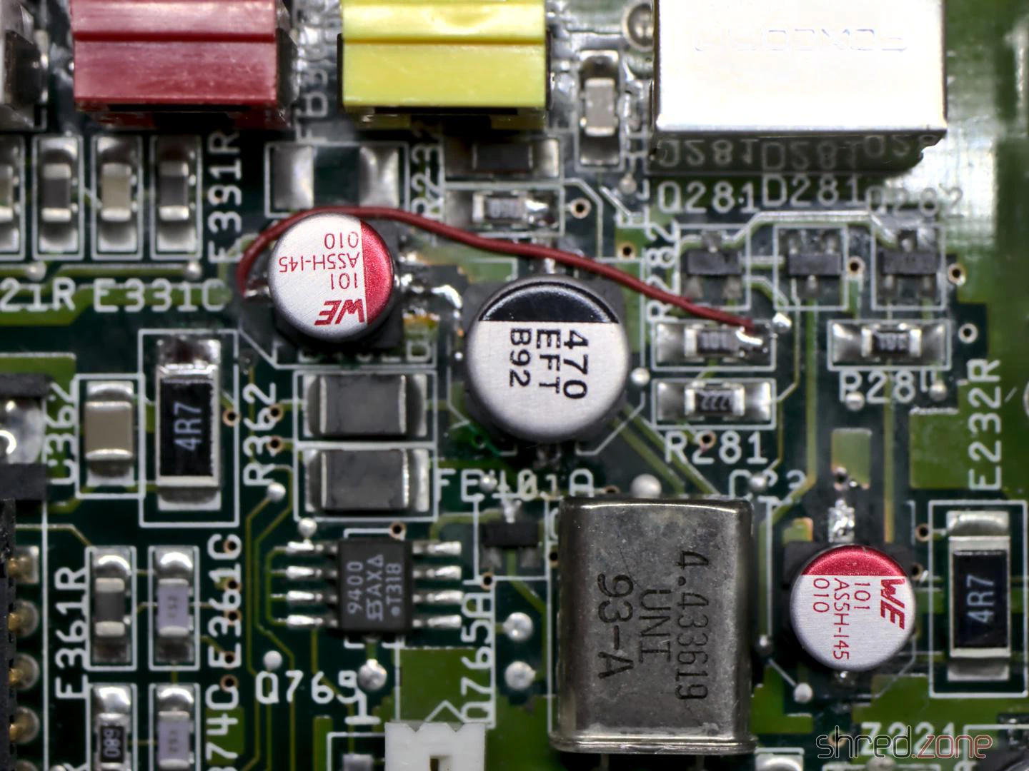
I also found a broken via near C409, which carries the CSYNC signal. As a result, the video sync signal is missing at the outputs. I repaired it by drilling out the via, exposing the connected tracks on both sides, then threading a thin wire through the hole and soldering it to the tracks. (Note: This only works if the via has no connection to one of the inner layers of the board, which was the case here.)
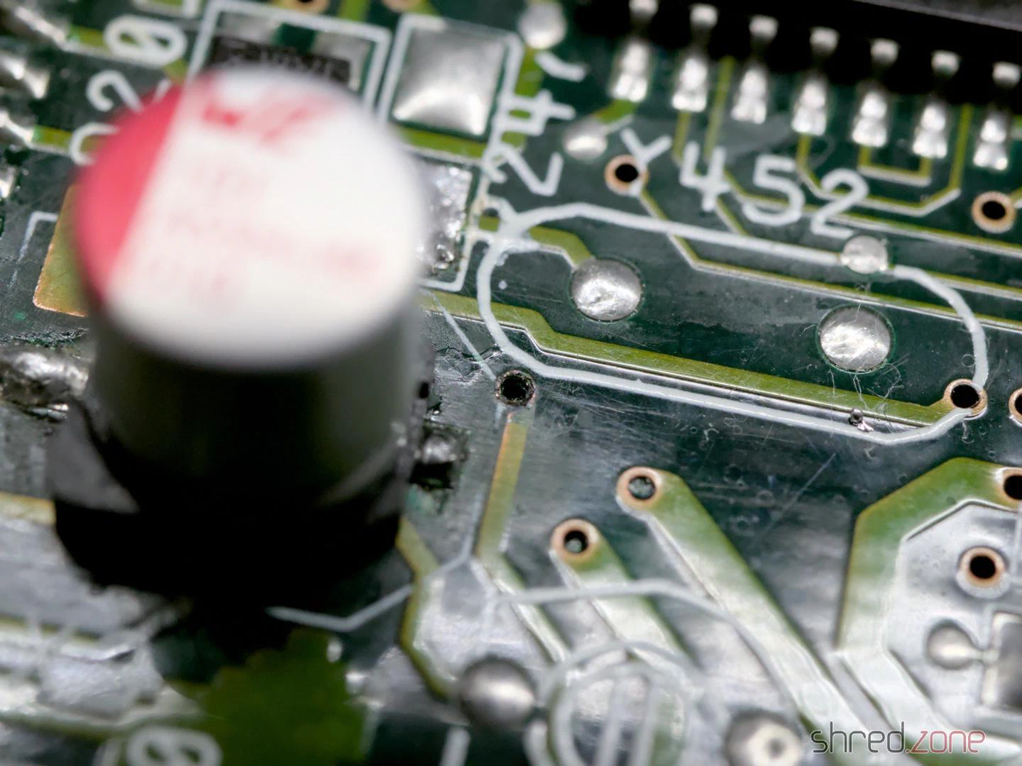
Overall, there were several reasons why the machine no longer showed a video picture.
By the way, two TH capacitors on the board have a peculiarity. At C408 and C811, the silkscreen shows the positive pole on the wrong side. This led to even Commodore soldering the capacitors in the wrong way round from the factory, which is why you will find quite a few CD³²s with bulging capacitors in this spot. I decided to solder in SMD capacitors there too, which can be soldered in as shown on the silkscreen.
So, power on, and to my surprise the Amiga worked again.

I checked all video and audio outputs and found a signal everywhere. The machine also ran stably. The mainboard was thus repaired and overhauled.
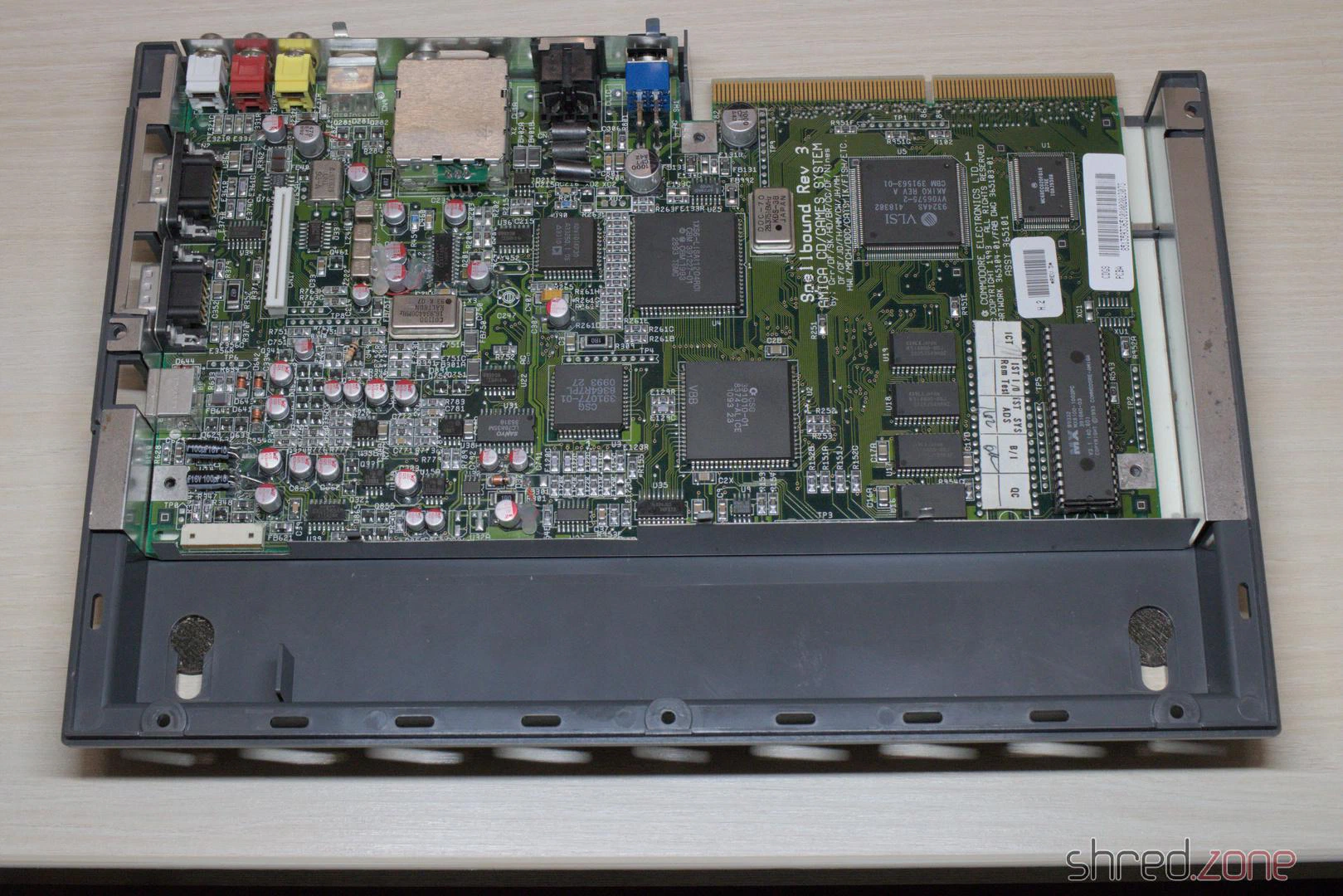
Even though it was an unexpectedly difficult affair, I am glad that I was able to repair the machine.
In the next part I will replace the laser module and calibrate the CD drive.
When I saw this Amiga 1200, I immediately felt sorry for it. The case and the keyboard were already heavily yellowed, but even worse was the botched attempt to fit a Gotek drive into the case. To make room for it, the previous owner obviously broke open the area around the floppy drive with pliers or wire cutters, completely ruining the beautiful old case.
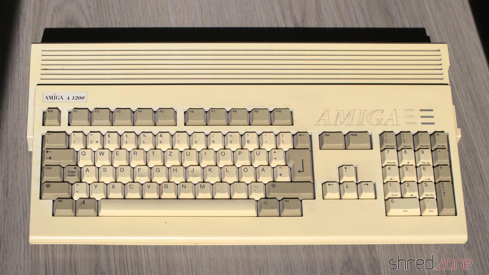
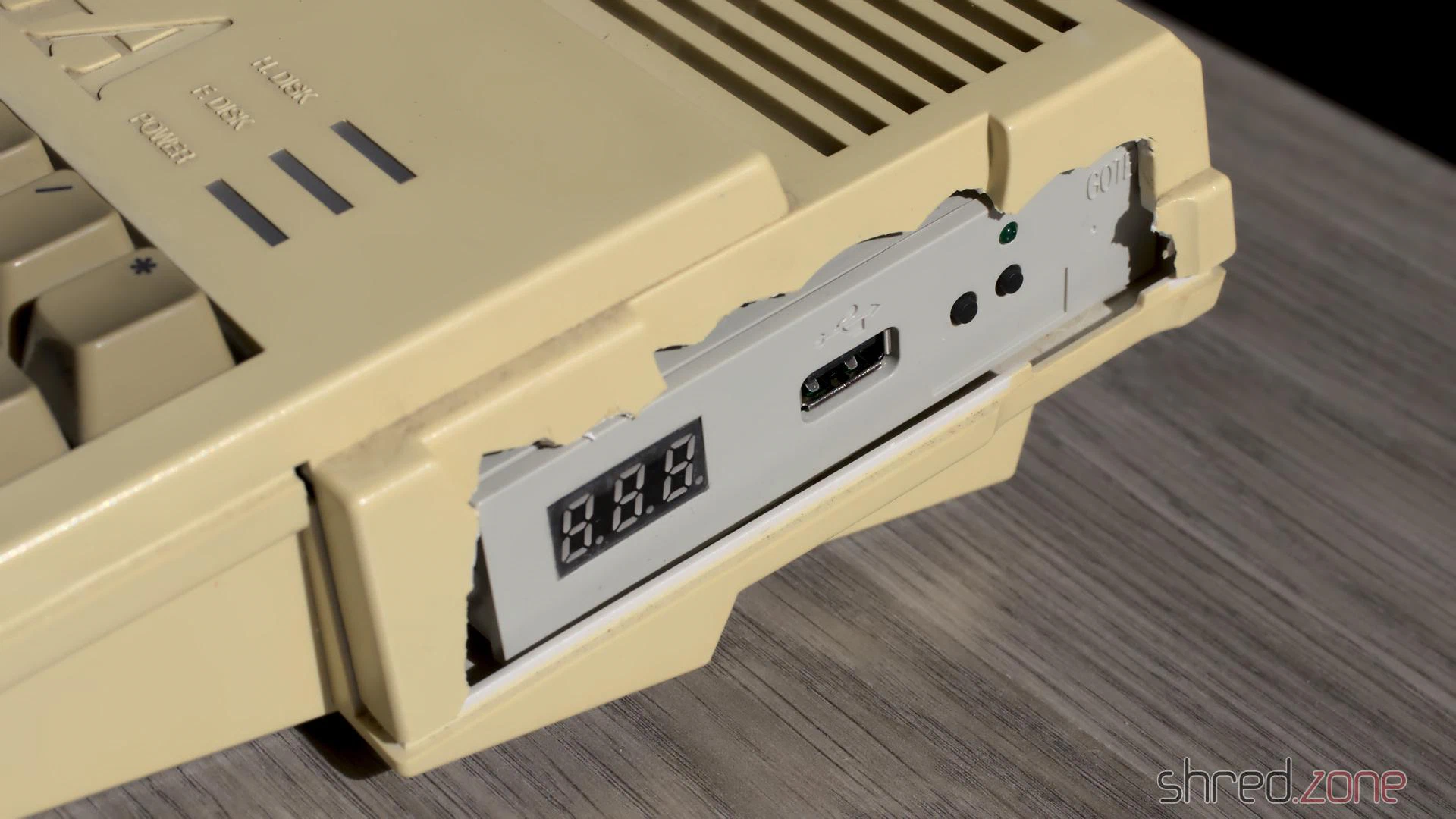
Originally, I had planned to bleach the case and the keyboard. I wanted to tidy up the ugly opening at the floppy drive with a rotary tool and then close it with a 3D-printed part as best as possible.
But then I had a much better idea. 😁
The motherboard
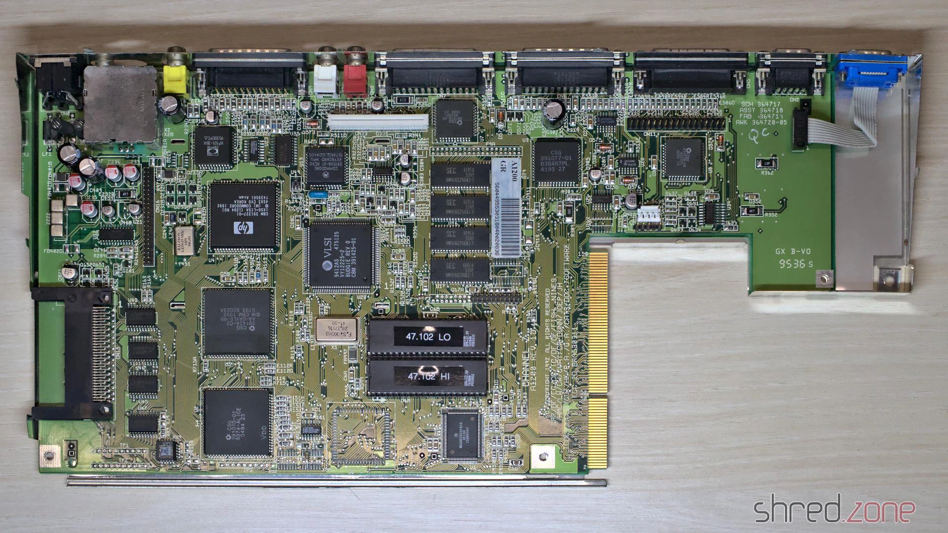
First, let’s take a look inside. A Rev 1D.4 board in good visual condition is installed. I replaced the electrolytic capacitors and updated to AmigaOS 3.2.1.
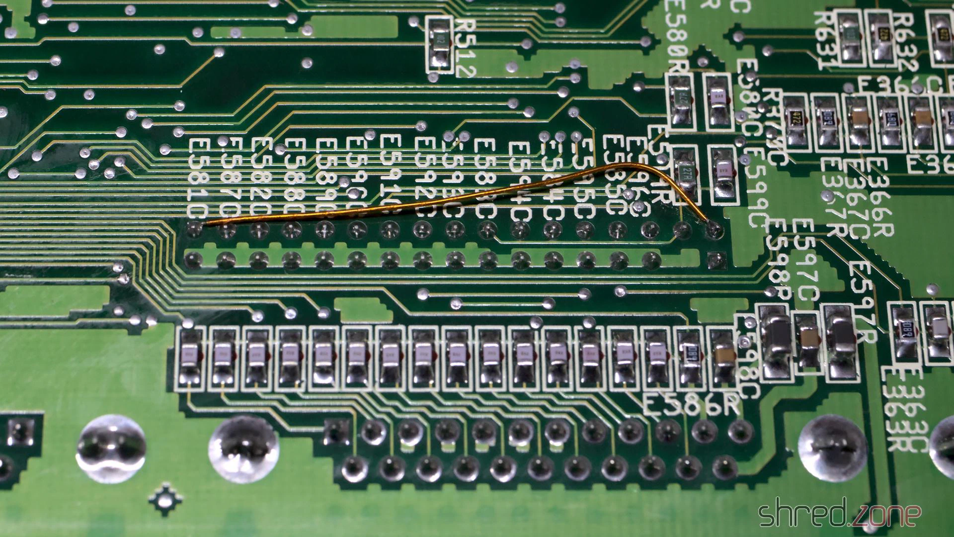
On the underside of the board, I found a copper wire for a so-called “floppy fix”. When Escom produced the last Amiga 1200s, there were no Amiga floppy drives left. Instead, they installed standard PC floppy drives. However, many games and demos didn’t run on the machines modified in this way.
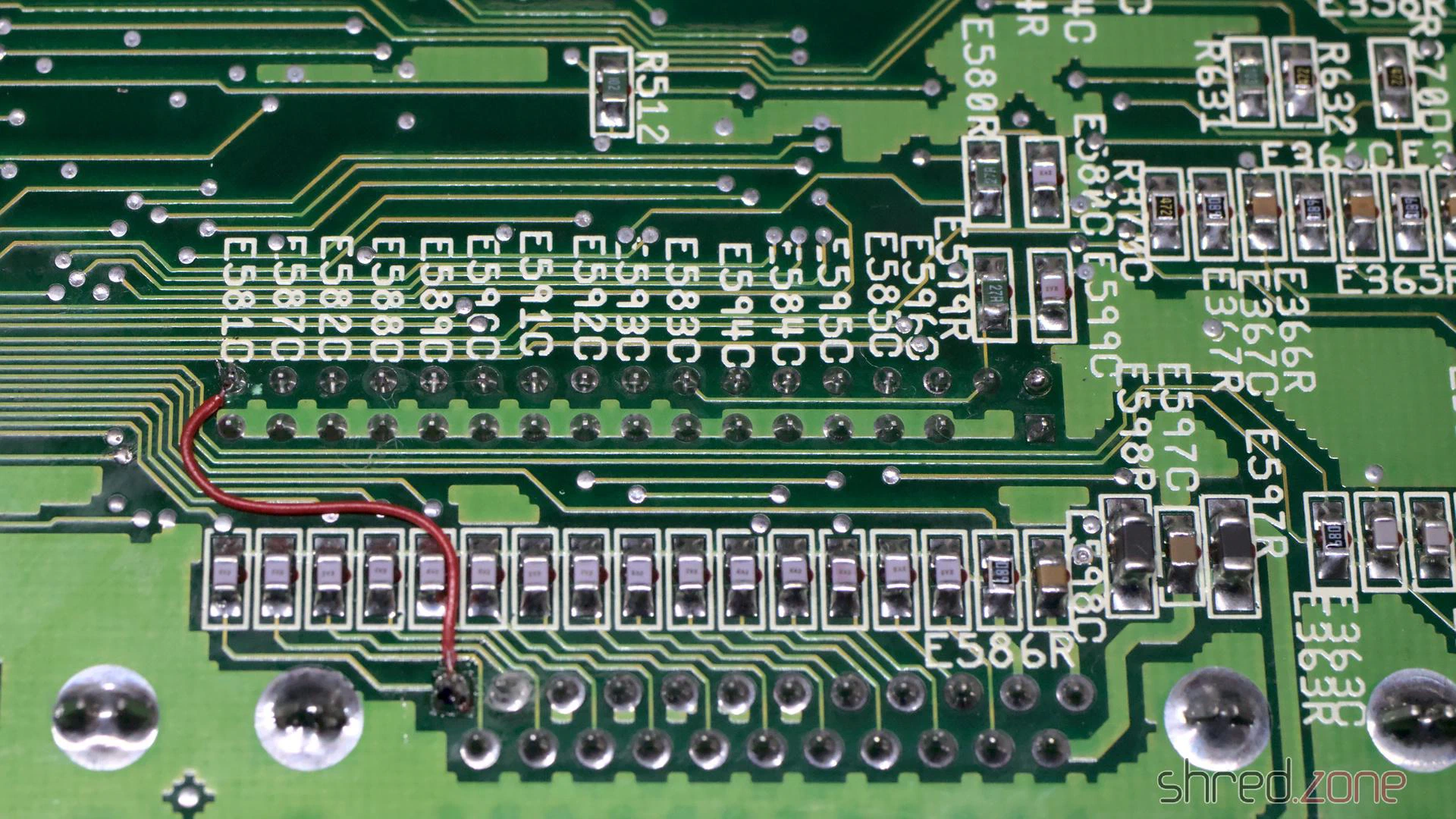
The original floppy drive of this computer was no longer present, and Gotek drives can perfectly emulate Amiga floppy drives. So I decided to reverse the floppy fix. To do this, the jumper wire is first removed. To restore the original RDY signal, a wire is then soldered from pin 34 of the internal drive connector to pin 1 of the external floppy port.
Since I was working on the underside of the board anyway, I also wanted to remove E123C and E125C to improve the stability of accelerator cards. However, the capacitors hadn’t even been populated in the first place, so that was sorted.
That meant it was time for a first thorough test run. Everything went well so far, until I noticed that the right mouse button didn’t work on either port. A separate blog article describes the cause and the fix. In short: you have to replace four resistors with ferrites.
My work on the board was finished after that. It now passed all diagnostic tests.
The extras
As with my other restorations, I don’t just overhaul the machine, but also future-proof it with a few extras.
First up: the yellowed case with the ugly cut. It was clear to me that the case would never look truly nice again, even with a half-decent restoration attempt. Besides, I had always wanted a black Amiga. Therefore, I treated the Amiga to a brand new, black a1200.net replica case instead.
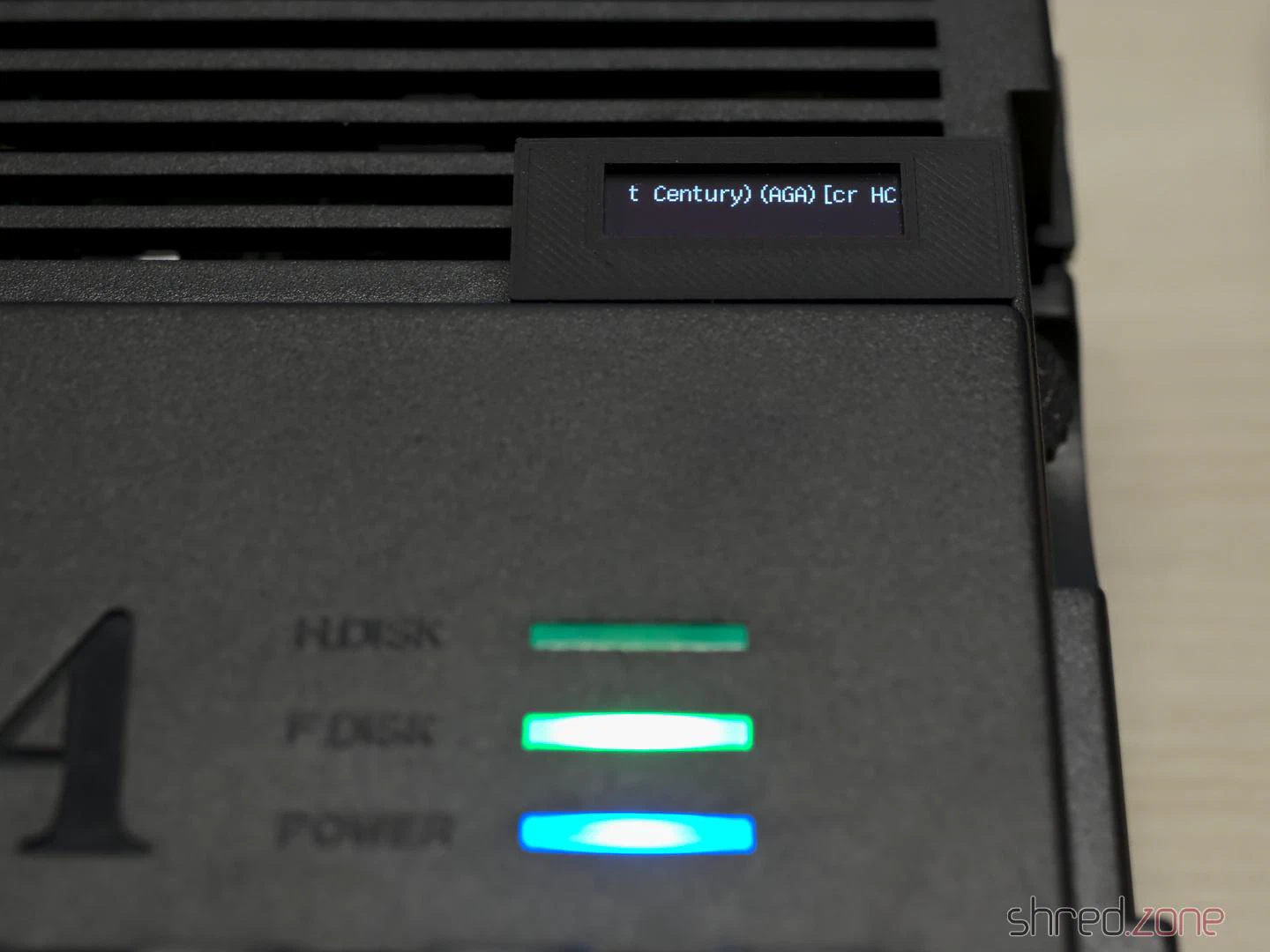
The floppy drive was missing. Instead of the Gotek drive that was originally supposed to take its place, I chose a Centuriontech GoEX drive. Instead of a USB stick, it uses an SD card. It also features a rotary switch that makes selecting the floppy image easier. Matching OLED displays are available as accessories, but for my new Amiga, I wanted a much smaller display that wasn’t as conspicuous.
I used a 0.91" OLED display, the kind you can find in practically any maker shop. Here it is important to swap pins 1 and 2 when soldering the cable, as the power pins on this type of display are swapped compared to the original GoEX display module.
I printed an A600 display module case, which fortunately also fits an A1200. I joined the individual parts together with hot glue. In hindsight, I should have used normal glue, as the hot glue softened the PLA of the print a little. The cable is then routed through the cooling vents of the Amiga and the module is clipped on, gluing is not required.
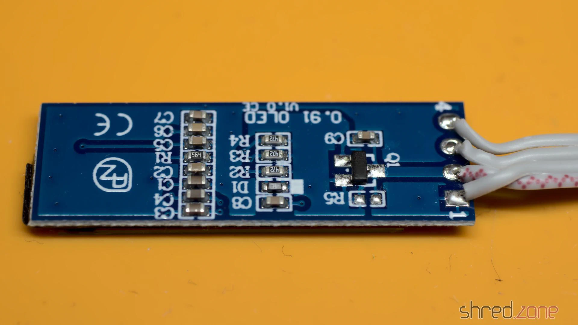
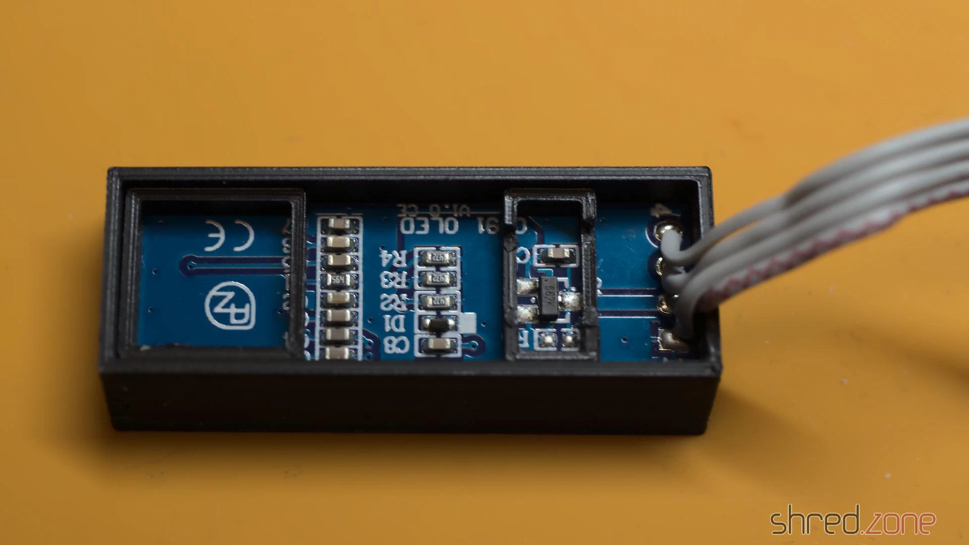
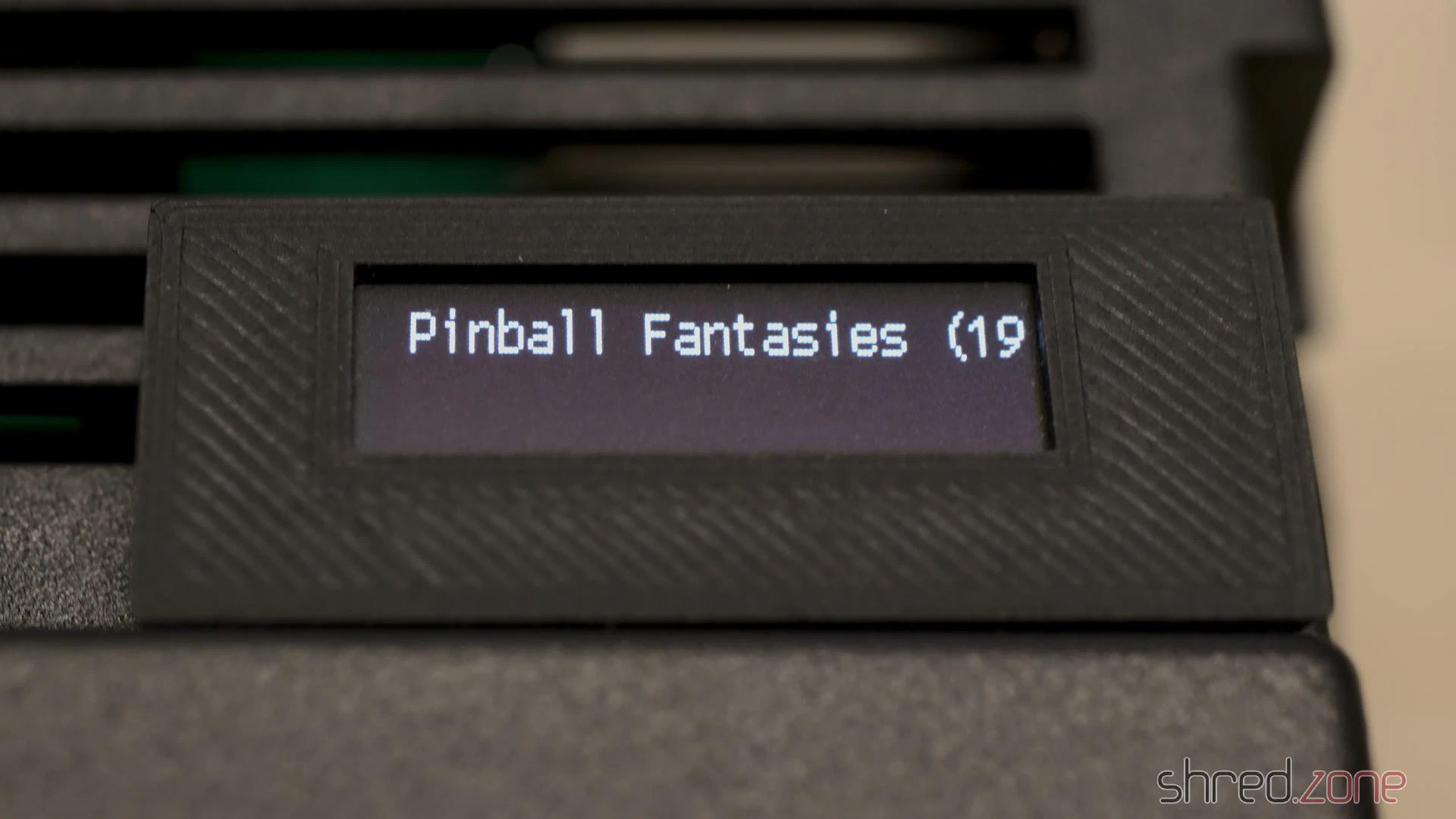
For the GoEX to use this OLED size correctly, a file named FF/FF.CFG must be created on the SD card with the following line:
display-type = oled-128x32
For a pixel-perfect image via HDMI, I also installed an Indivision AGA MK3. It turned out that the a1200.net replica case seems to have slightly different dimensions than the original case. I therefore designed a modified trapdoor and bracket for this case type.
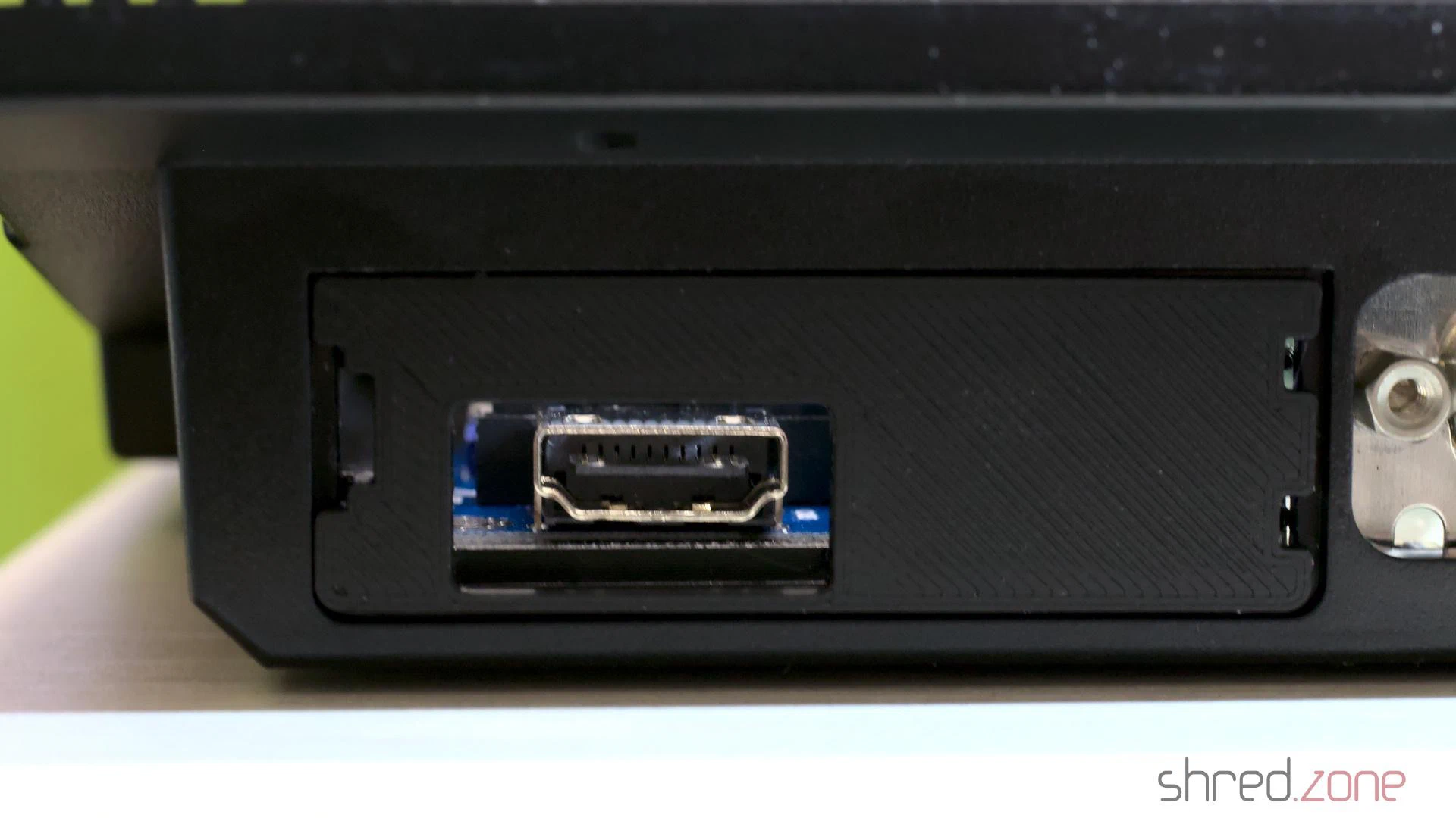
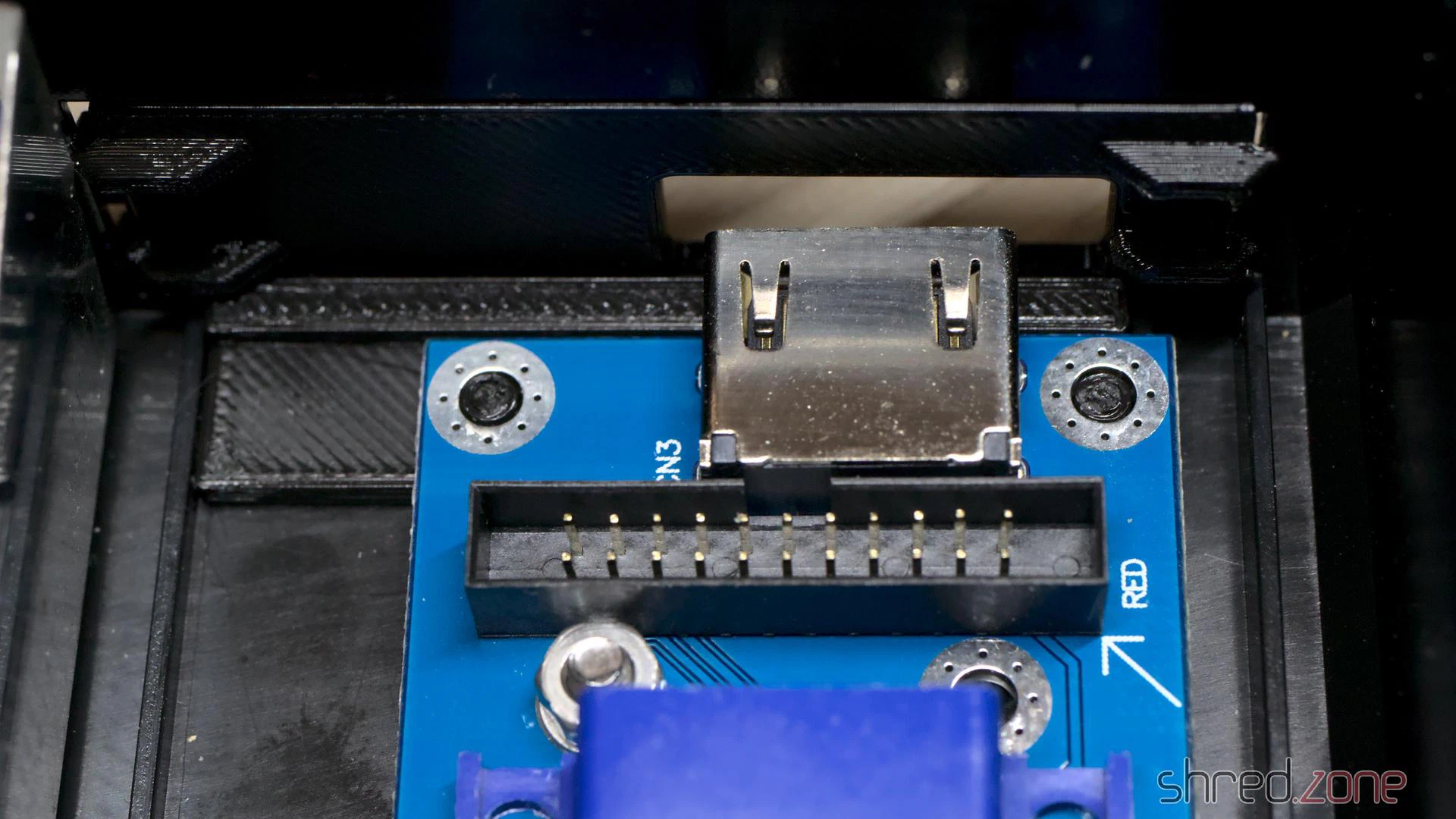
When I got the Amiga, there was already a Marpet Developments M1207 RAM expansion in the expansion slot. It was treated to a fresh coin cell battery and now provides the machine with an additional 4 MB of Fast RAM, a 68882 FPU and a real-time clock.
And last but not least, the machine got custom LEDs, with the power LED in my signature colour, blue.
Assembly
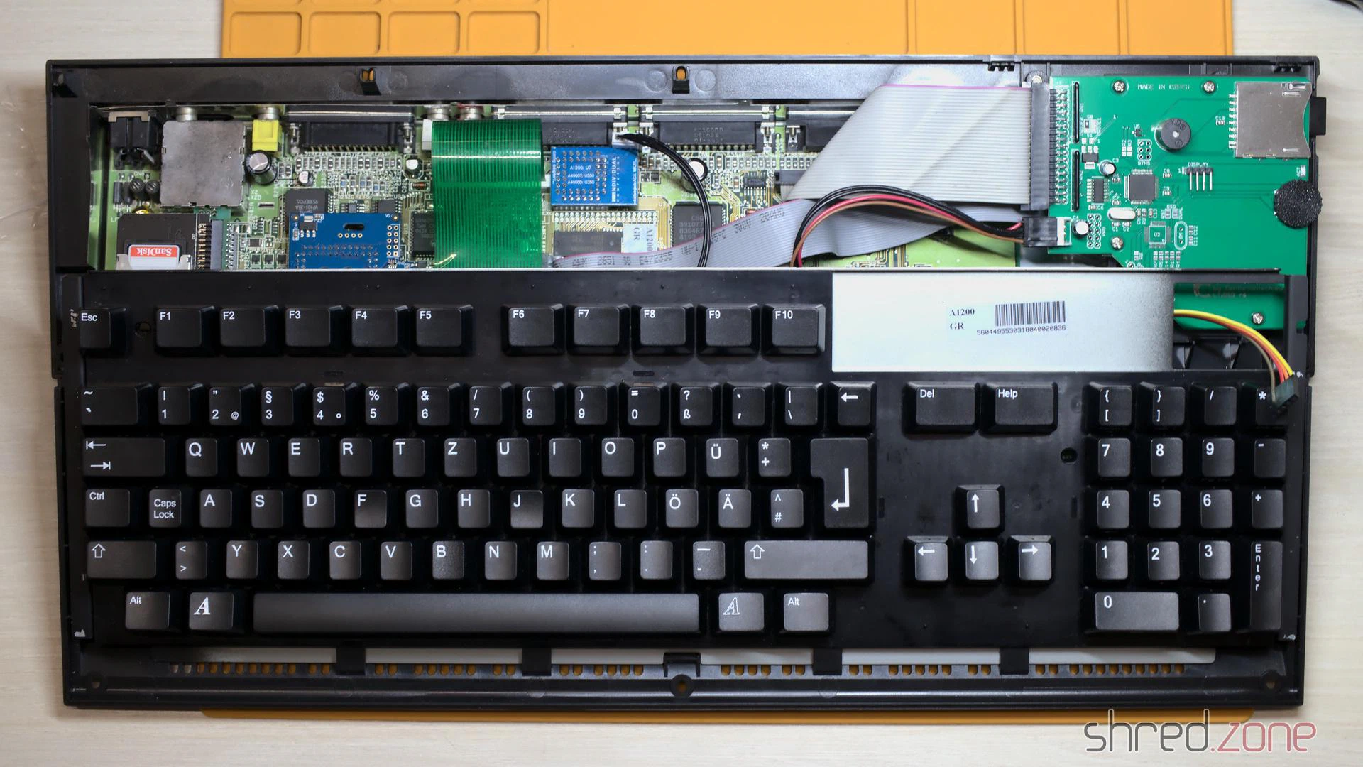
What’s still missing? The black keycaps, of course, to match the black case. After many years of waiting, they were finally available, and I had a set delivered just in time for Christmas.
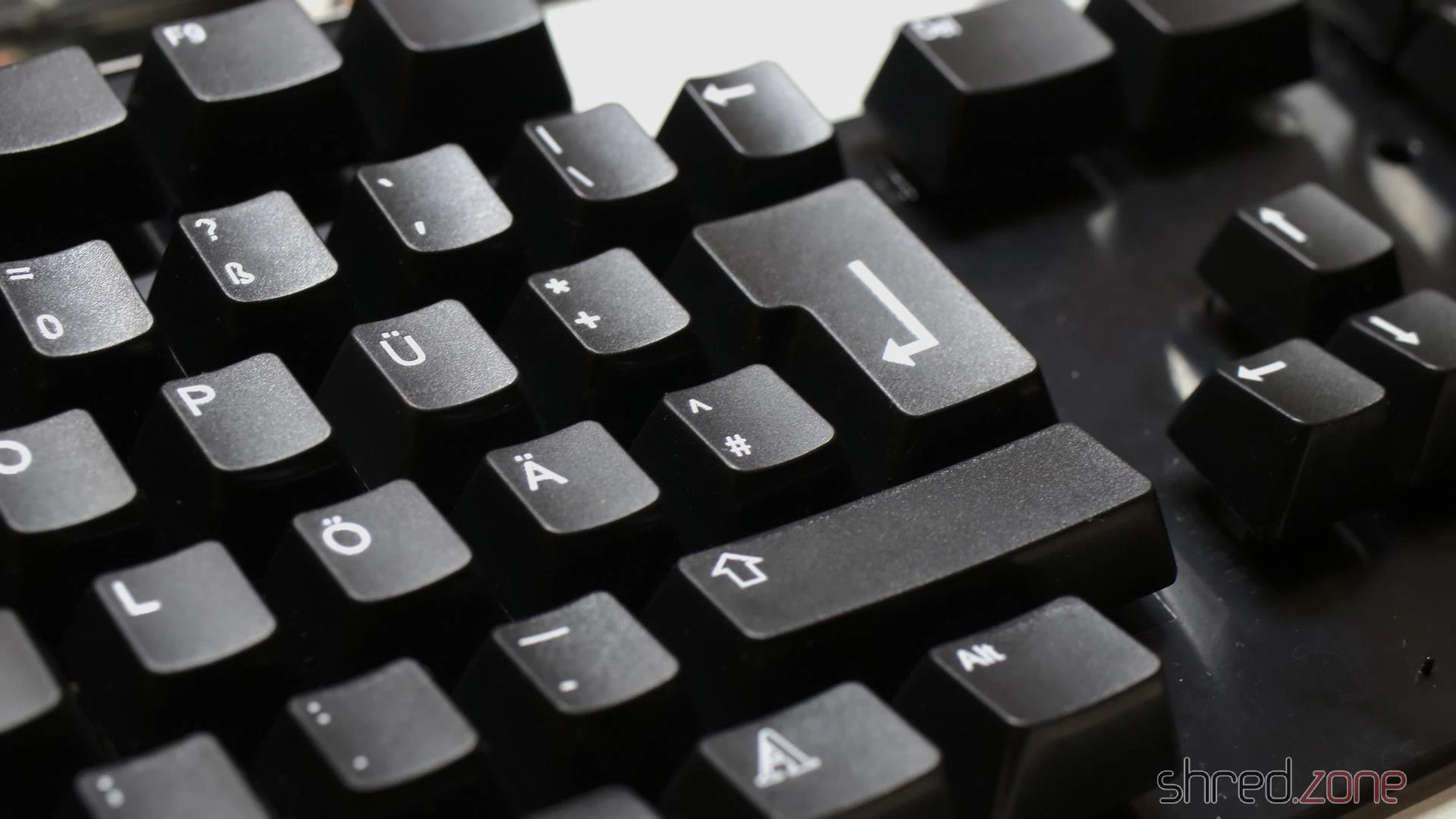
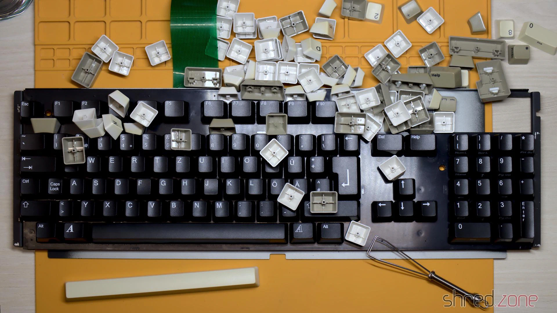
Unfortunately, a matching badge is not included with the black case, but Badgeman had something suitable in stock.
After that, the Amiga was ready for final assembly.
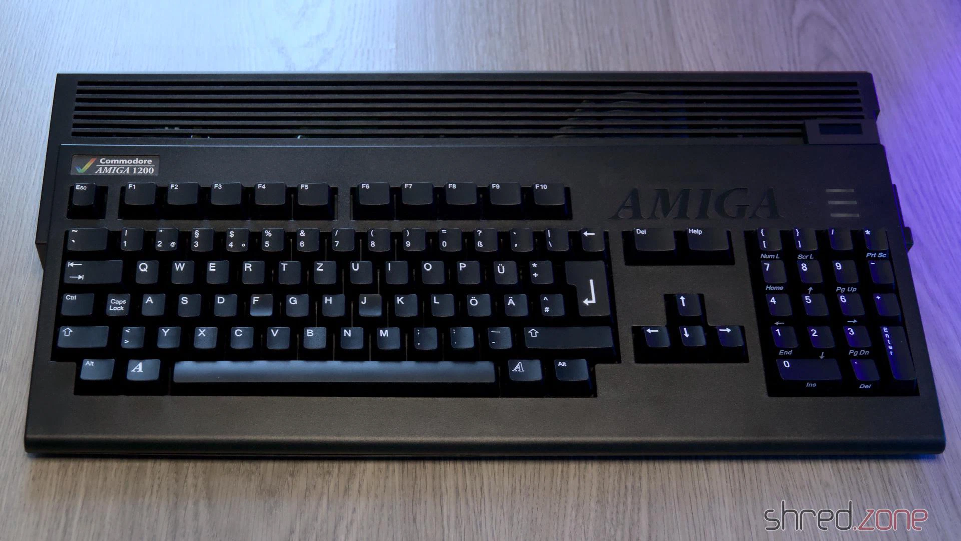
If Commodore had given us a choice of case colour back in the 1990s, I would have chosen a black Amiga. And now here it is, a completely black Amiga 1200 with a totally new exterior and a modernised interior.
In the previous part, I refurbished the keyboard of the Amiga 1000. It was in a bad state, and truly deserved to get its own part. Now I will replace the floppy drive with a Centuriontech GOEX on pills floppy simulator, and then put everything back together.
Floppy LED
The floppy LED of the Amiga 1000 is not connected to the mainboard, but to the floppy drive. The GOEX drive does not provide a similar connector, so I had to come up with a solution. Fortunately, the Amiga made it faily easy.
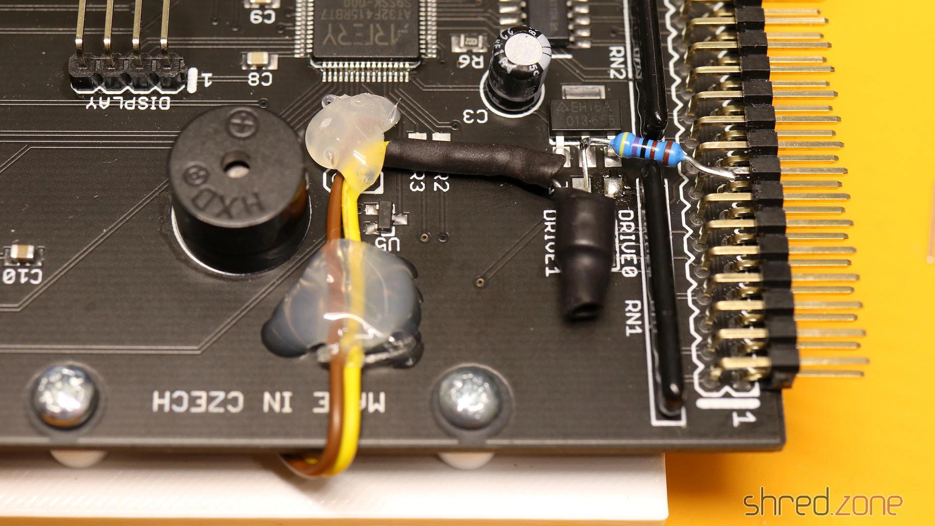
On all Amiga models, the floppy LED represents the state of the drive motor. It lights up as long as the motor is powered. On the Amiga 1000, the motor of the internal drive is controlled by a MTR0LOW, the motor is powered, and the floppy LED is supposed to light up. The 7438 buffer inside the Amiga has a maximum output current of 48mA, while the LED has a forward current of 30mA, so in theory the LED (and a 120Ω series resistor) could be connected directly to the MTR0
I used a BC557, but any other standard switching PNP transistor will do as well. For the LED, I preferred to have a green floppy LED instead of the original red one. I used a Dialight 521-9266, which has the same dimensions as the original LED. There should be a pullup resistor on the MTR0
On the GOEX board, +5V can be found on an unused pad next to the voltage regulator. GND can be found at an unused header for an optional encoder.
On Screen Display
The GOEX drive needs some kind of display, to show the floppy disk file that is currently selected, and other options. My first plan was to glue a tiny OLED display to the front of the case.
However, the “GOEX on pills” model comes with an OSD connector. It reads the CSYNC signal from the Amiga, and generates a pixel signal that is overlaid to the Amiga RGB signal. Depending on the color component the pixel signal is connected to, the OSD text is either red, green, or blue (with the corresponding complementary color as background).
The CSYNC signal can be taken from pin 12 of U6A. The pixel signal is connected to one of the 75Ω resistors: R25 (red), R24 (green), or R23 (blue). The wire must be soldered to that end of the resistor that is closer to the monitor connector, otherwise the OSD overlay will not be visible on white screens.
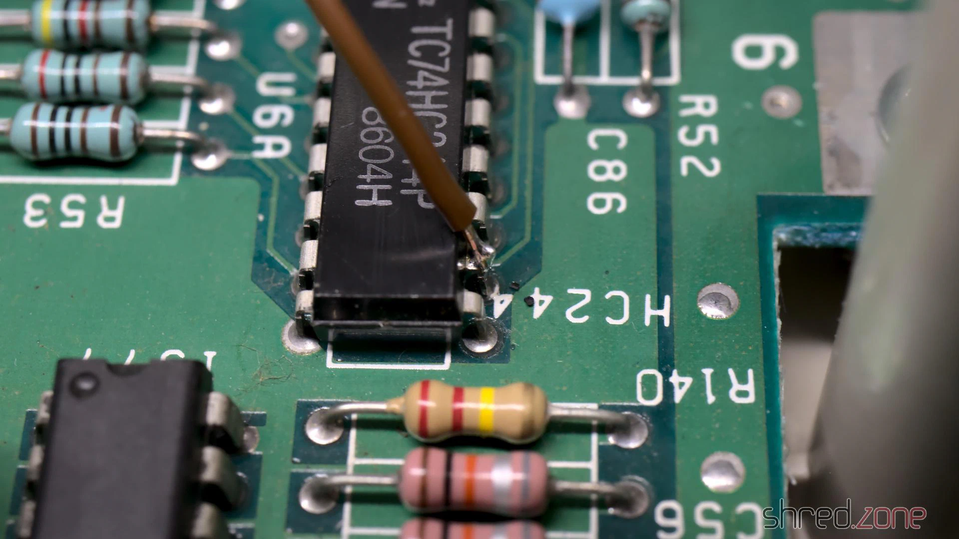
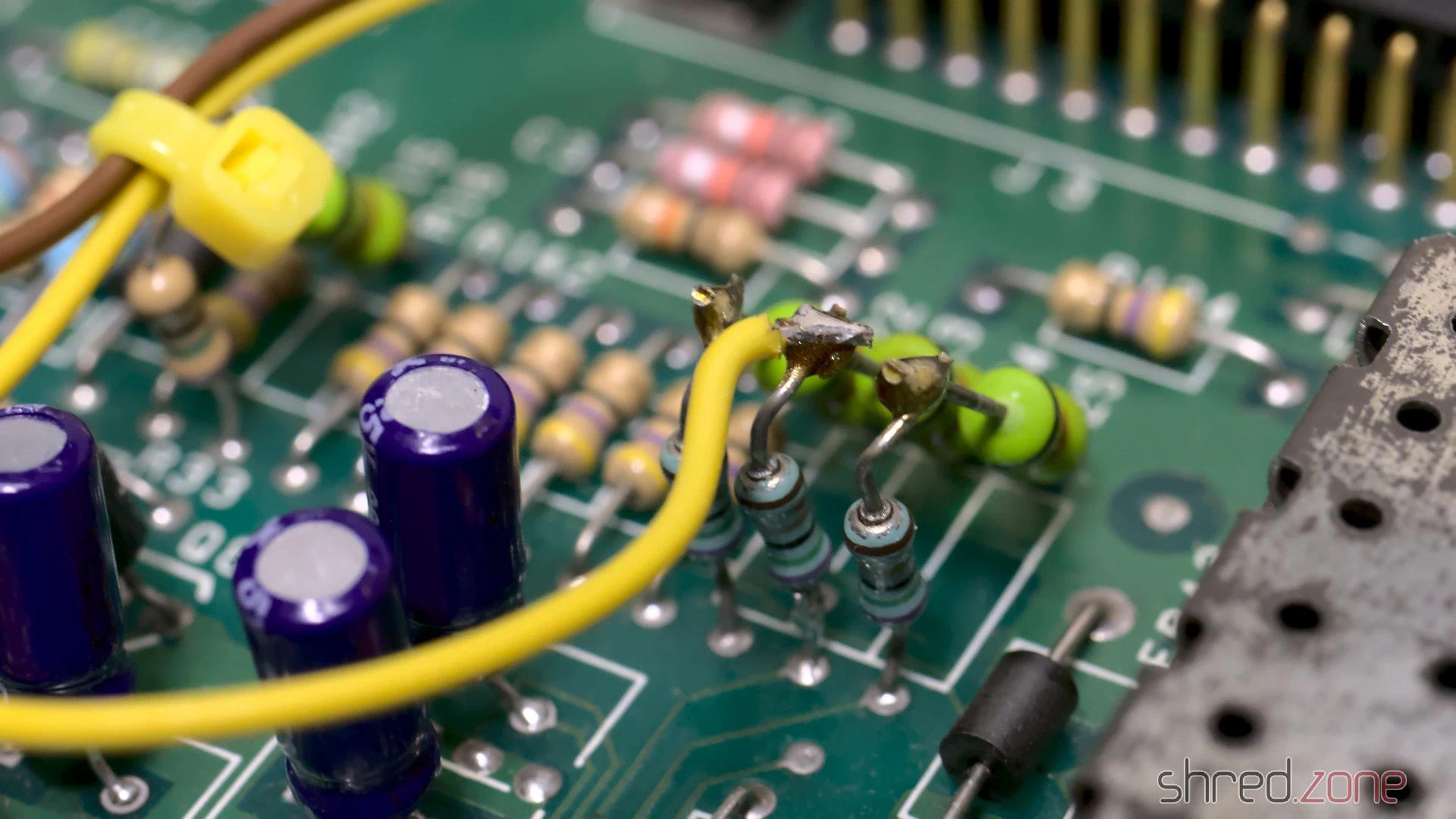
The other end of the two wires are connected to the respective CSYNC and RGB pins of the OSD header of the GOEX drive. It is also possible to control the GOEX drive with the Amiga keyboard, but I didn’t want to do more hardware modifications, especially if it involves soldering wires directly to one of the CIAs. I prefer that I still have to touch the floppy slot for changing floppy disks, even if it’s just virtually.
Reassembly
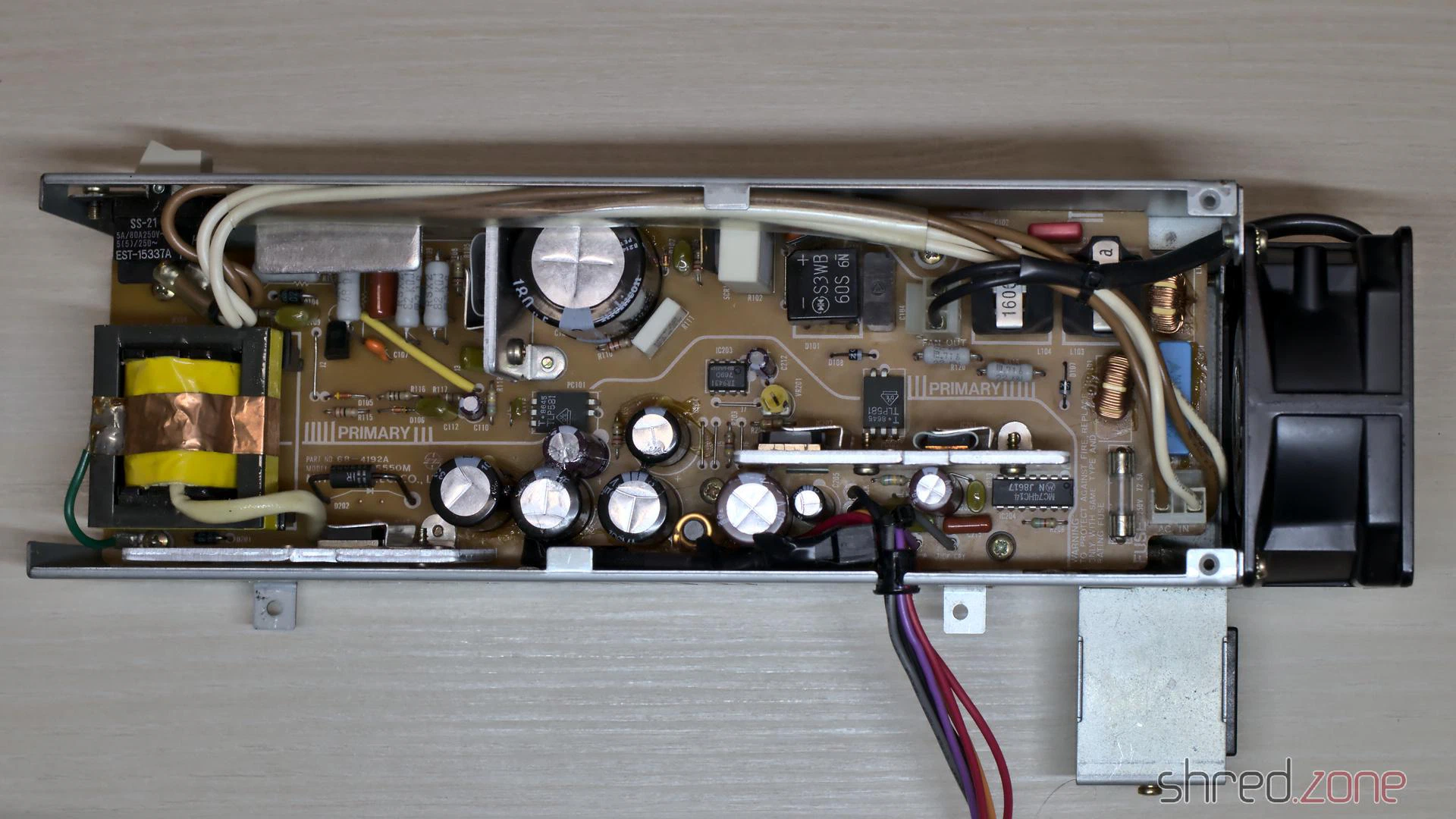
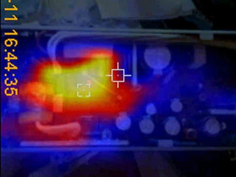
A trained technician should definitely overhaul the PSU, to avoid damage to the hardware or spectacular explosions of safety capacitors. @DingensCGN of the a1k.org forum did an excellent job there. He replaced all electrolytic capacitors, and did a full load test including checking the temperatures of the components with a thermographic camera. A big shout-out to him!
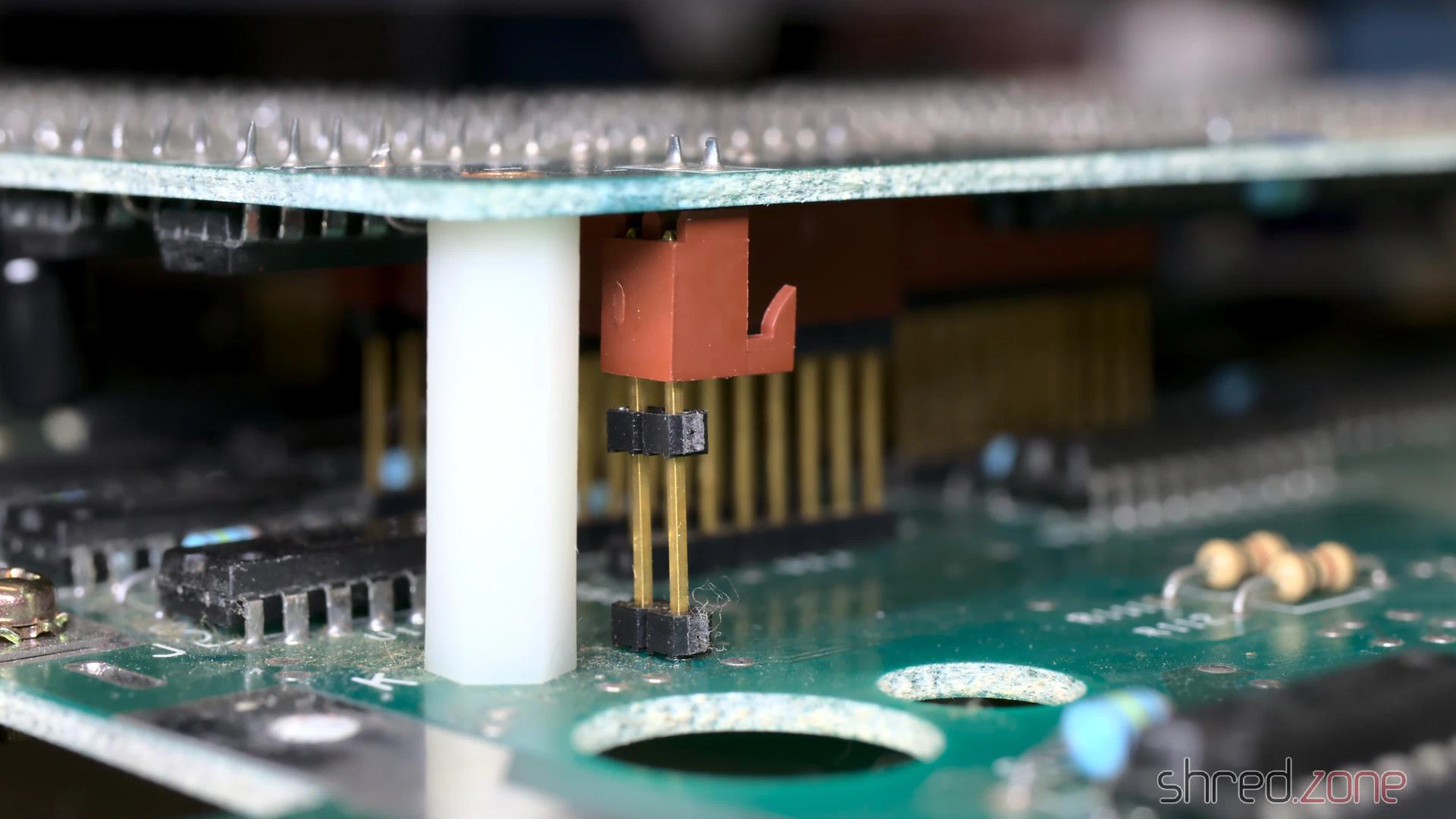
This Amiga has a separate piggyback board, which I had removed for cleaning and re-capping. It is connected to the mainboard by some headers at different places, which makes reseating it a bit tricky. It is crucial that all headers are properly connected.
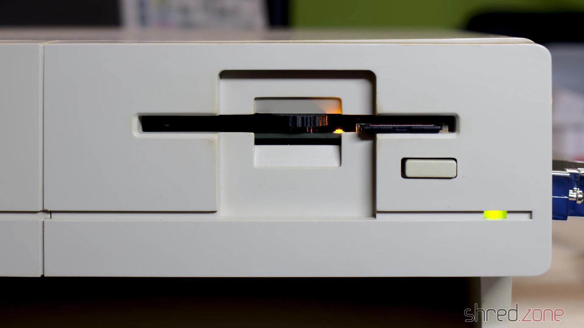
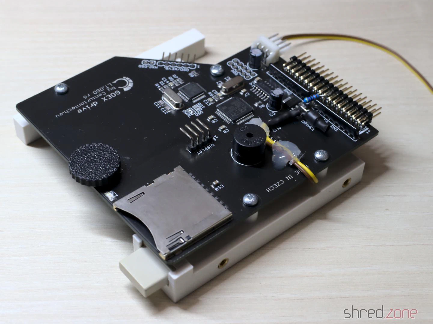
For the GOEX drive, I designed a 3D printed frame for the Amiga 1000. It holds the drive in its correct position, and also holds the original eject button so the hole in the front is closed. My intention is that the GOEX drive should be as invisible as possible, so the original look of the Amiga 1000 is maintained. I guess I managed that.
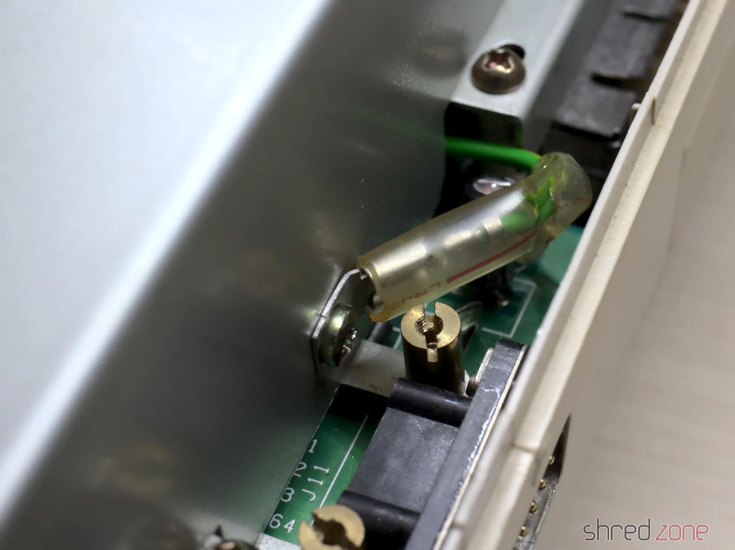
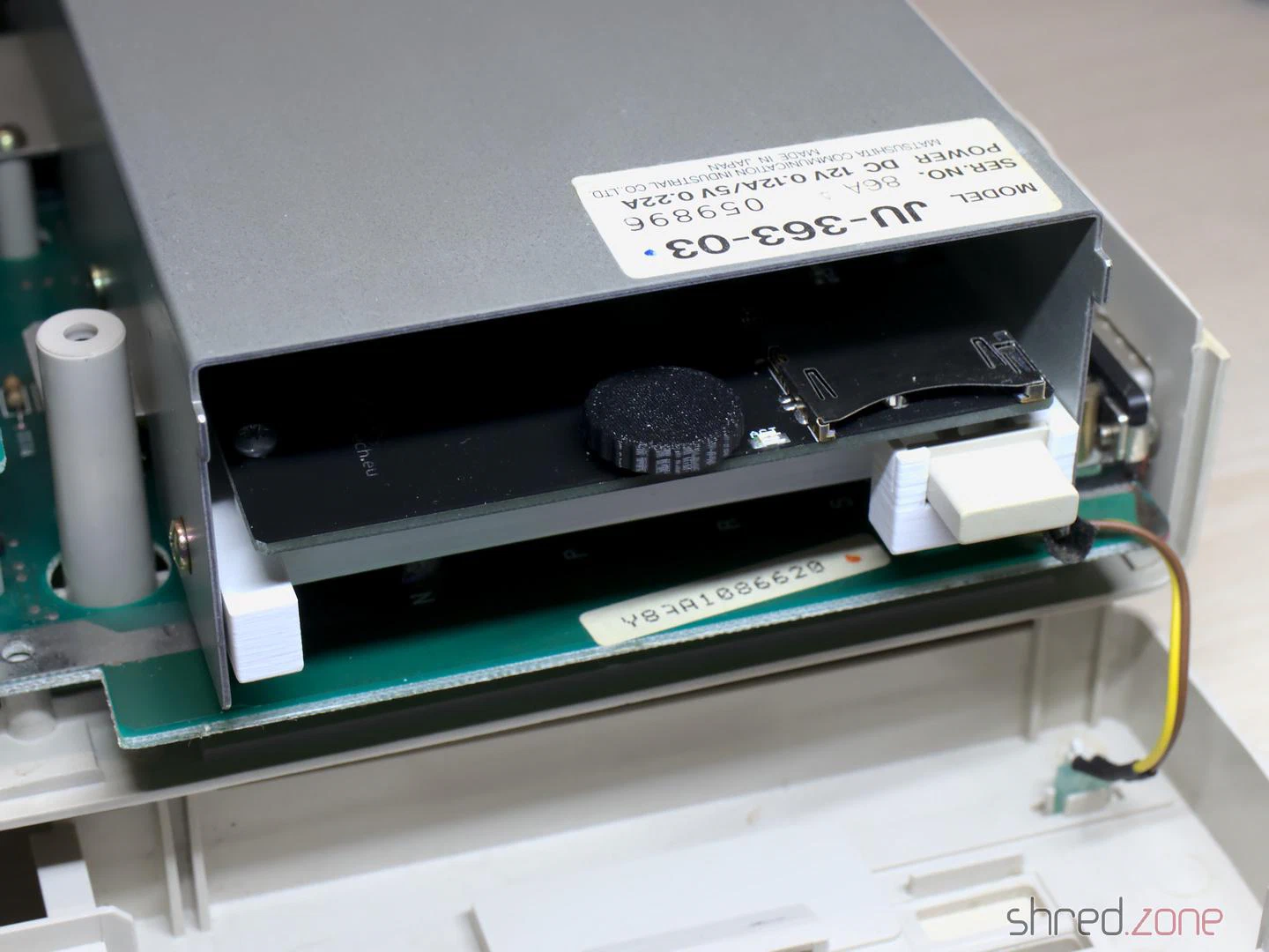
And that’s it. The system is fully assembled now.
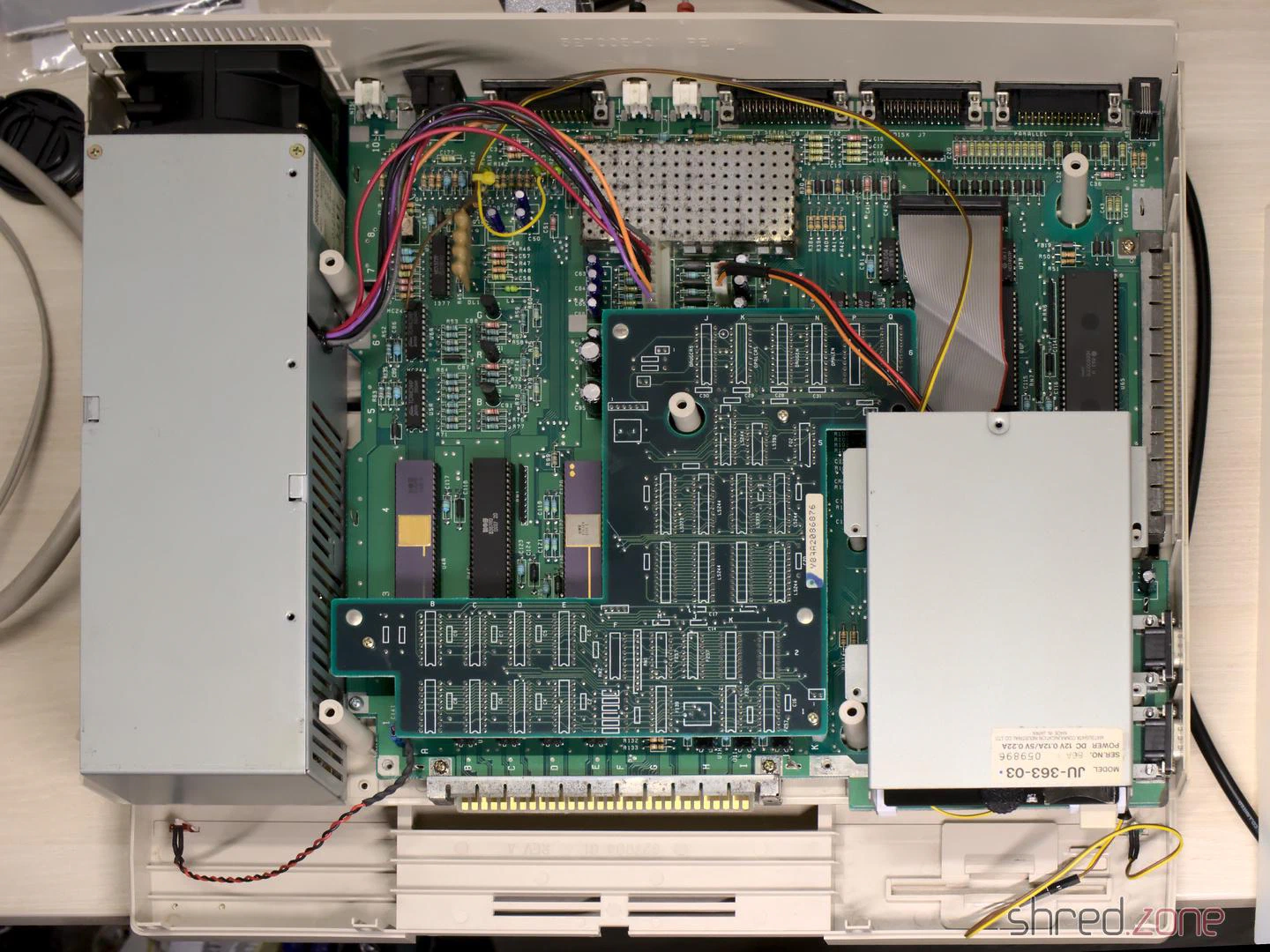
I mounted the top shield, attached the front plate, closed the case, and connected the 256KB memory expansion to the front slot.
And then came the moment of truth. I flipped the power switch. The system started up. I expected the 230V PSU fan to be rather noisy, and was very surprised that it is almost inaudible, and could easily compete with modern ultra-silent 12V fans of the same size.
Then the famous Kickstart screen appeared, together with the FlashFloppy OSD.
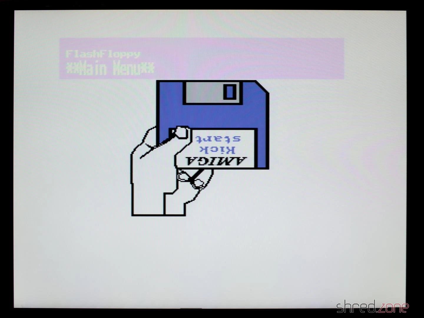
I loaded the Kickstart ADB file from the GOEX drive, and after that I changed to the first disk of the famous Red Sector Megademo. The Amiga just dutifully loaded it.
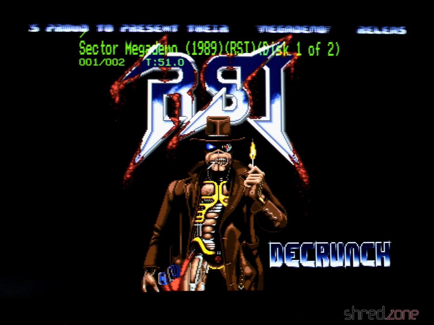
Everything ran smoothly! The green color of the OSD certainly adds a lot to the 1980s retro feeling of that machine. It looks quite like those OSDs on old TVs or VCRs. 😆
Configuring FlashFloppy
There were two things that were bugging me. The first was that I’d like to run a cold start of the machine as simple as possible, so the GOEX drive should always select the Kickstart ADF first when the system is powered up. The second was that the OSD was shown on the screen for much too long. It should disappear a few seconds after disk inactivity.
Both is easily configured. First, a directory called FF needs to be created on the SD card. Then a FF/FF.CFG file needs to be created, having this content:
image-on-startup = static
display-off-secs = 5
A second file called FF/IMAGE_A.CFG contains the file name of the Kickstart ADF file on the SD card.
Welcome!
And that’s it! I am, and have always been, a big fan of the Amiga. I learned a lot on my Amigas, and they were the foundation of my career as professional software developer.
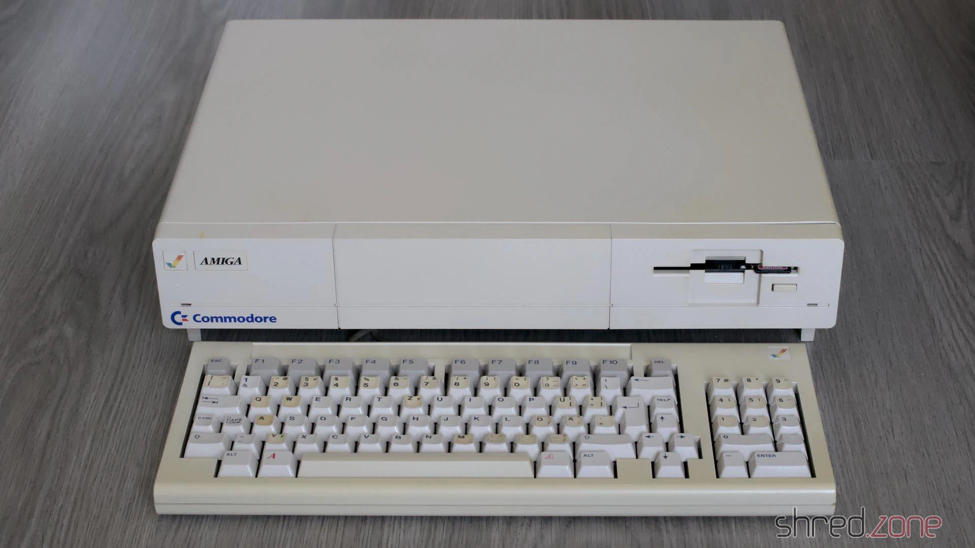
I always considered the Amiga 1000 to be the pearl of my Amiga collection, and I am happy and proud that I got the chance to own such a beautiful machine now.
In this second part, I will take care about the keyboard. I expected that it would be the usual procedure: Cleaning the key caps and case, whitening the yellowed parts, dusting off the keyboard frame.
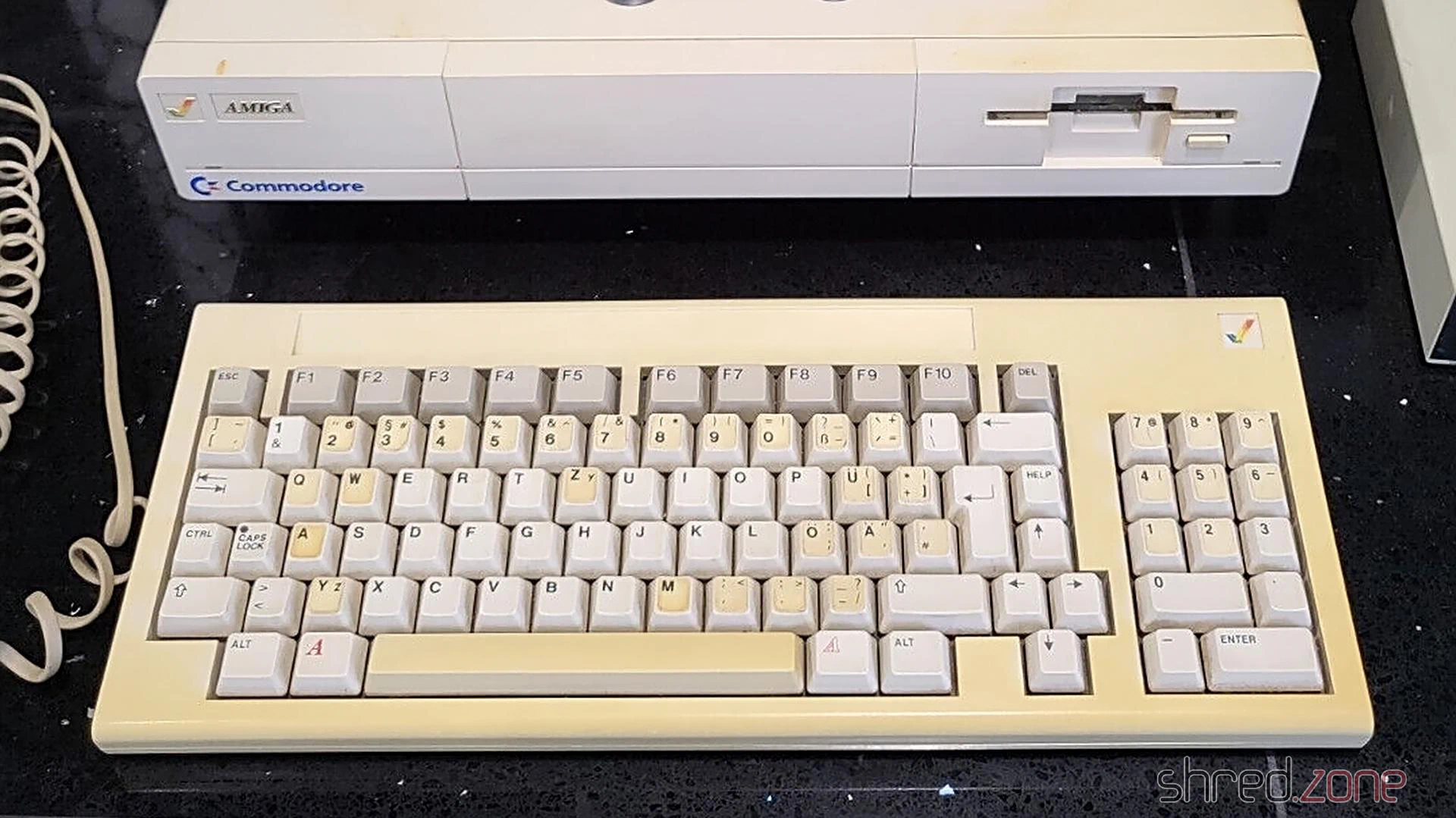
However, this time it wasn’t that easy.
The trouble started when I pulled off the key caps, but also pulled out the plungers of three keys. Fortunately this can be repaired, as the switches are easy to maintain. More about that below.
Keyboard Cleaning
The key caps were cleaned in an ultrasonic bath with a drop of rinse aid, and then brushed with a soft toothbrush.
Below the key caps, there is the keyboard frame where the switches are mounted. I found the usual filth that you would expect there after almost 40 years, but there was also flash rust, a crusty dirt layer, and… dead insects. I went outside and brushed off the insects and all the other loose dirt. Then I went back inside, and sprayed the frame with IPA, in an attempt to clean off the crust. The room immediately filled with an unhealthy stench of dust, dirt, and insect excrements. 🤢 Also, my attempts to remove the flash rust with a fiberglass pen wasn’t really successful. There was too much of it.
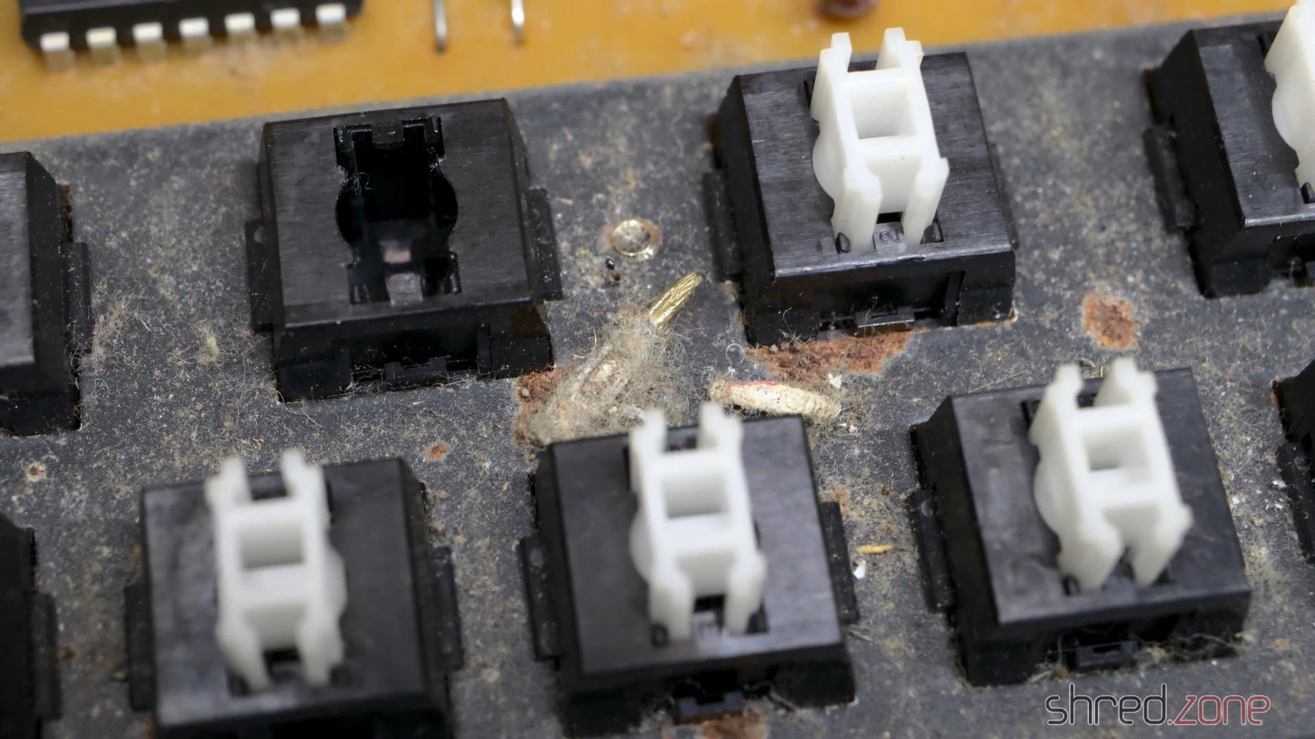
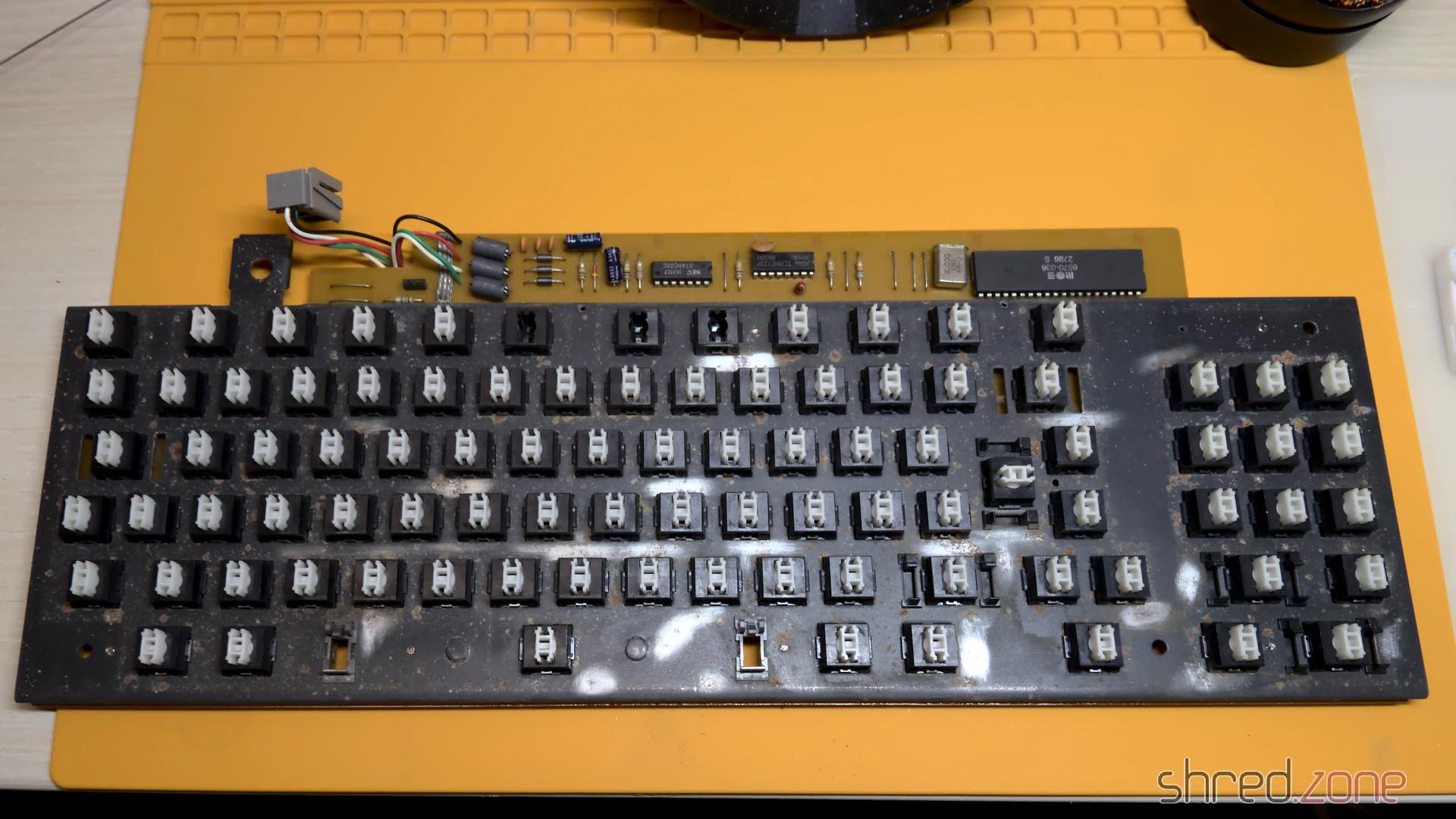
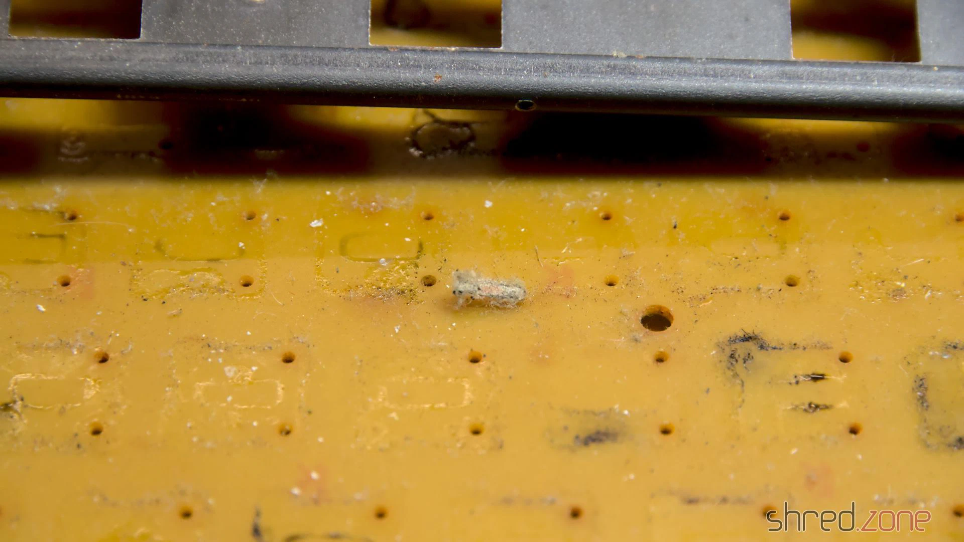
I wanted to avoid that I had to refurbish the frame, because it can only be removed after unsoldering all 91 switches (and one LED). But there was no other way to do it. So I unsoldered everything and removed the frame. On the PCB, I found dried stains from a liquid (maybe from a soft drink that had been spilled over the keyboard), and more dead insects. It confirmed that it was the right choice to go all the way.
I sanded down the old paint and the dirt crust from the frame (outside, and wearing a good filter mask). Then I spray-painted it in a matte black. It’s looking so much better now.
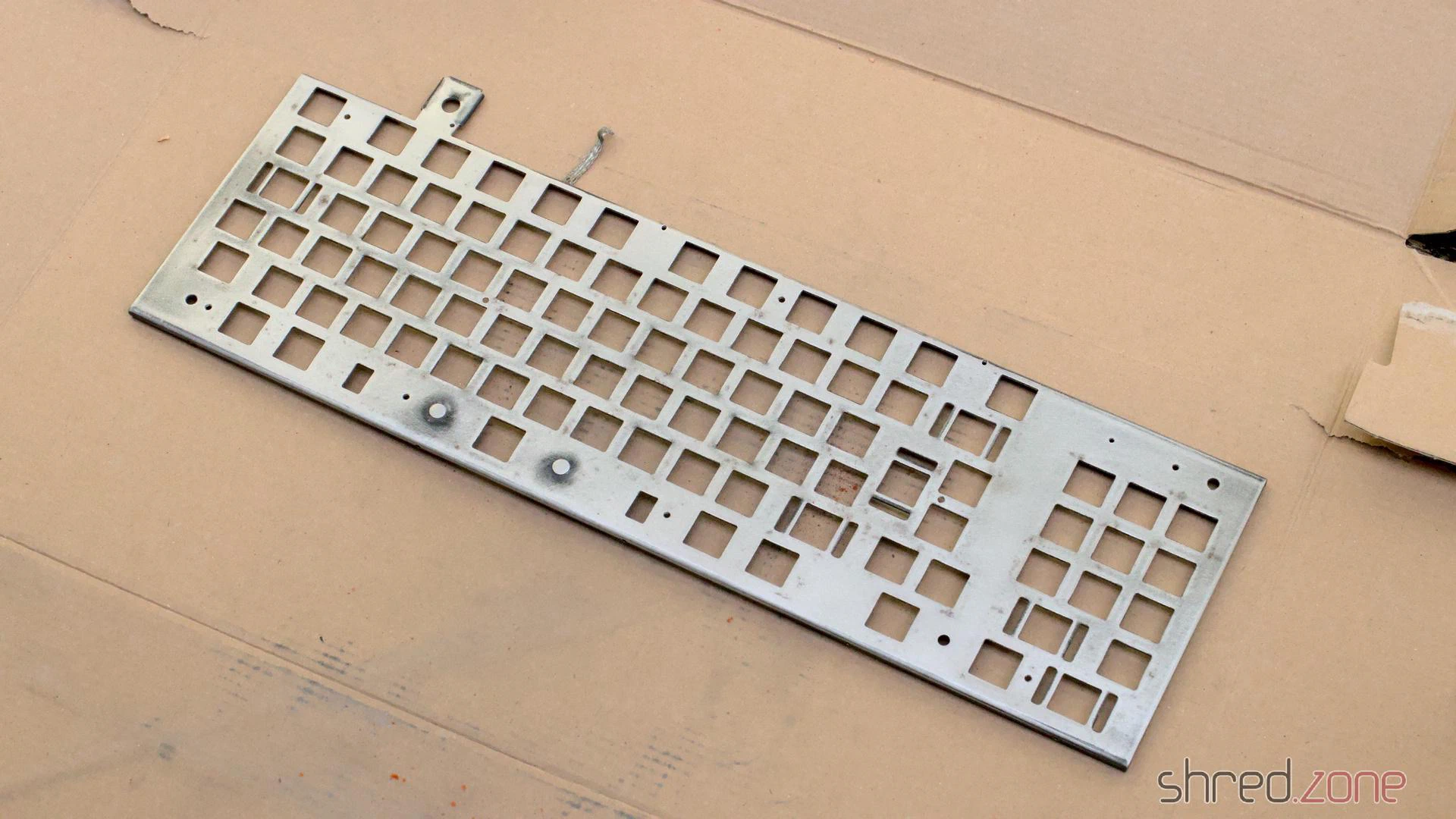
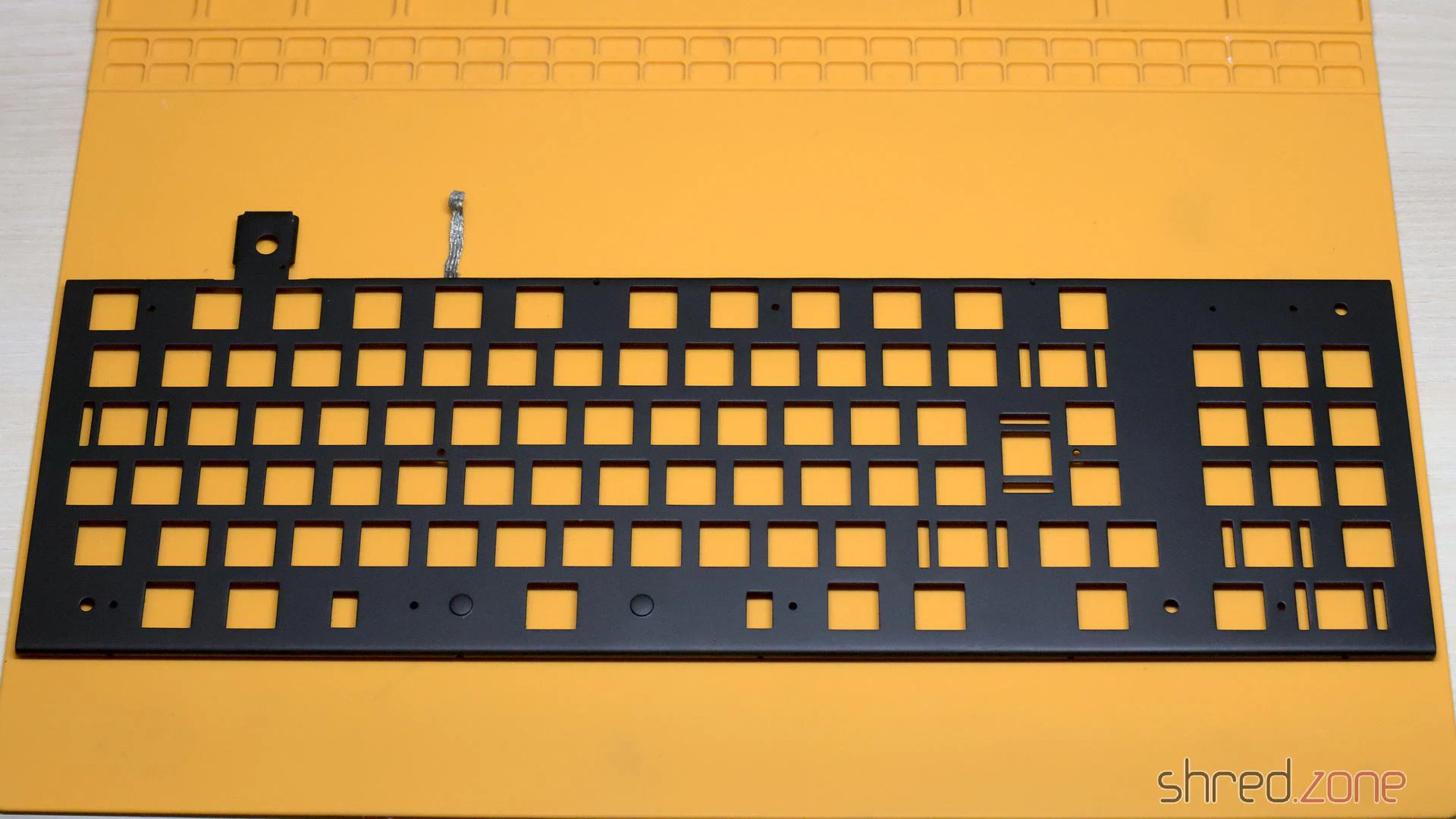
Refurbishing the Switches
The next bad surprise came when I was about to reassemble the keyboard. I tested all 91 switches for continuity when closed, but found only about 40 of them actually working. When I depressed the other keys, they either did not close the contact, or the plunger got stuck, or both.
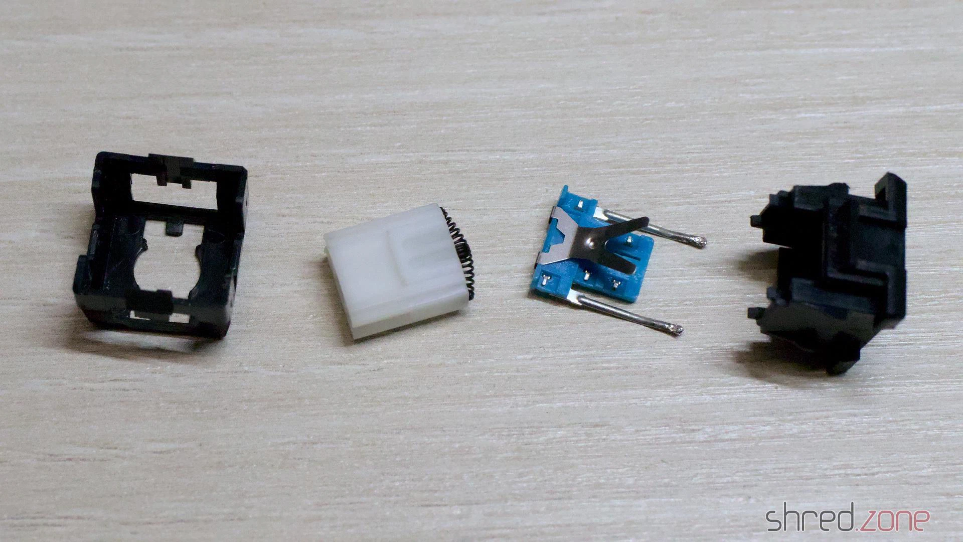
The switches that are used in the Amiga 1000 keyboard are Mitsumi Type 2 tactile switches. They are out of production by today, but they are easy to maintain. After trying the best approach with a couple of switches, I found the following procedure to be most successful.
The switch can be opened by putting a kind of blade (like the head of a flat screwdriver, or flat pincers) into the latch on both sides, and then carefully removing the cap with a blade or another screwdriver. The switch consists of four parts: The cap, the plunger, the switch plate, and the base.

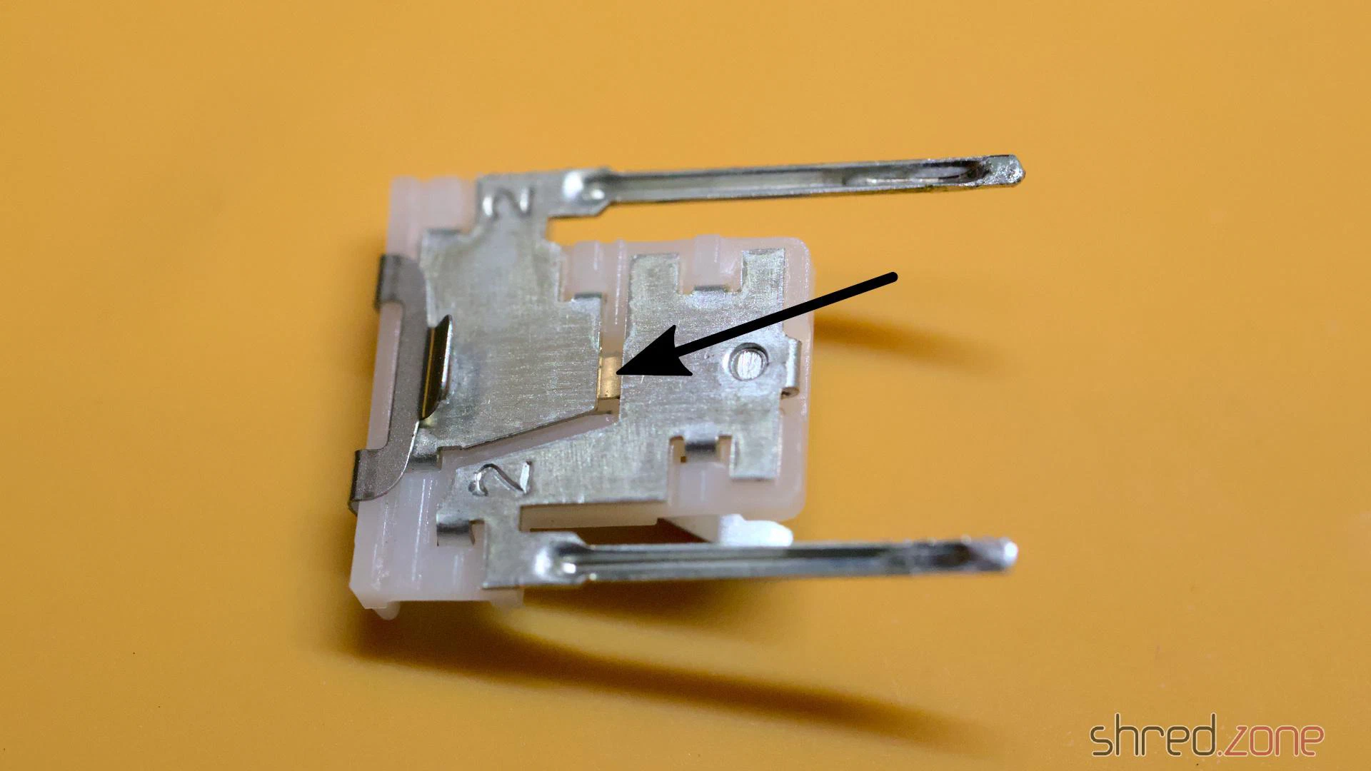
I cleaned the switch plate with contact cleaner spray. I also bent up the legs of the lever a tiny bit, so it will give a bit more pressure on the switch when the key is depressed.
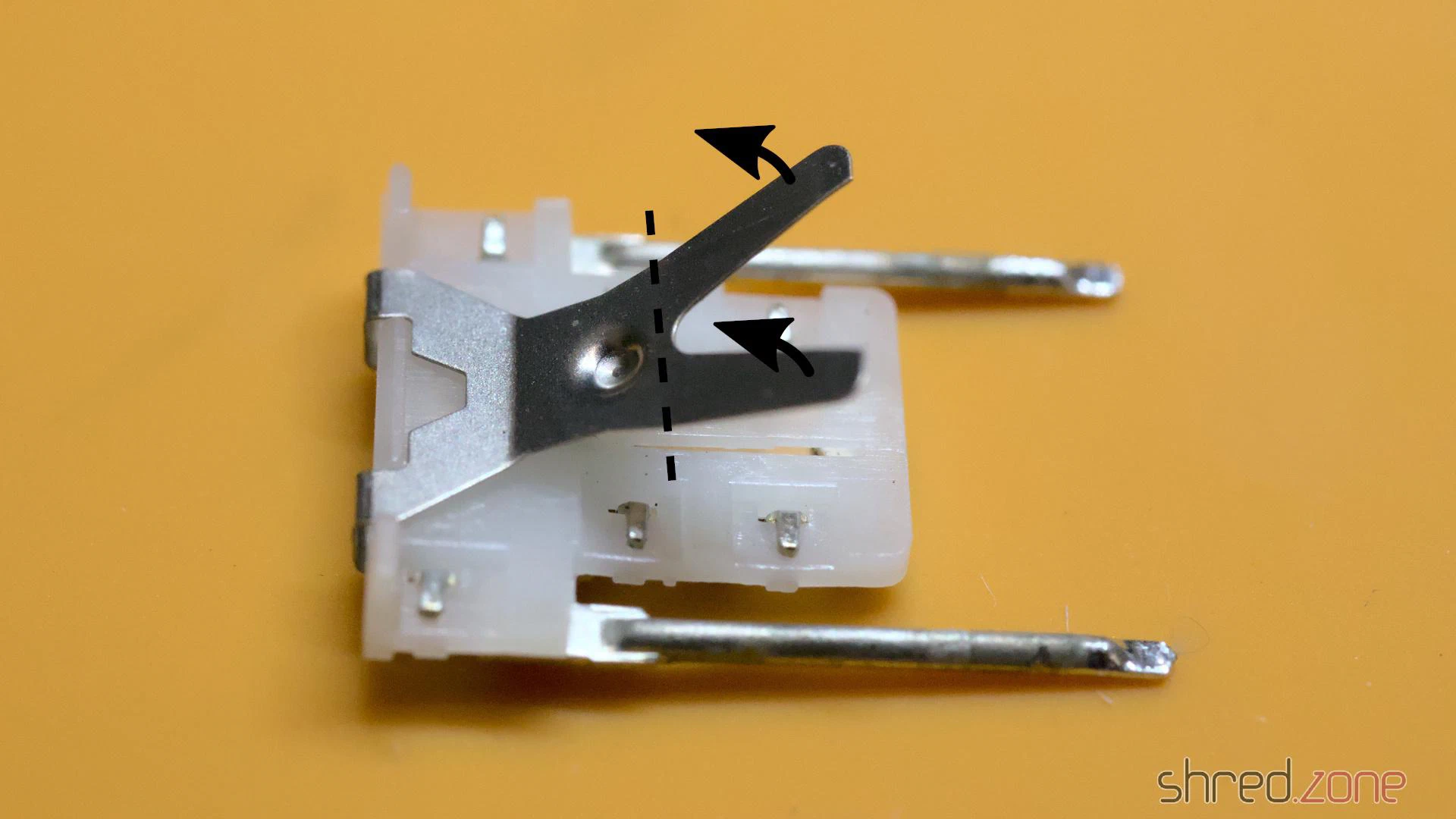
Finally, I applied a bit of silicone grease on both small sides of the plunger. It is important to use a very very tiny amount! If too much is used, the key will feel sluggish or might even get stuck. If in doubt, better skip this step.
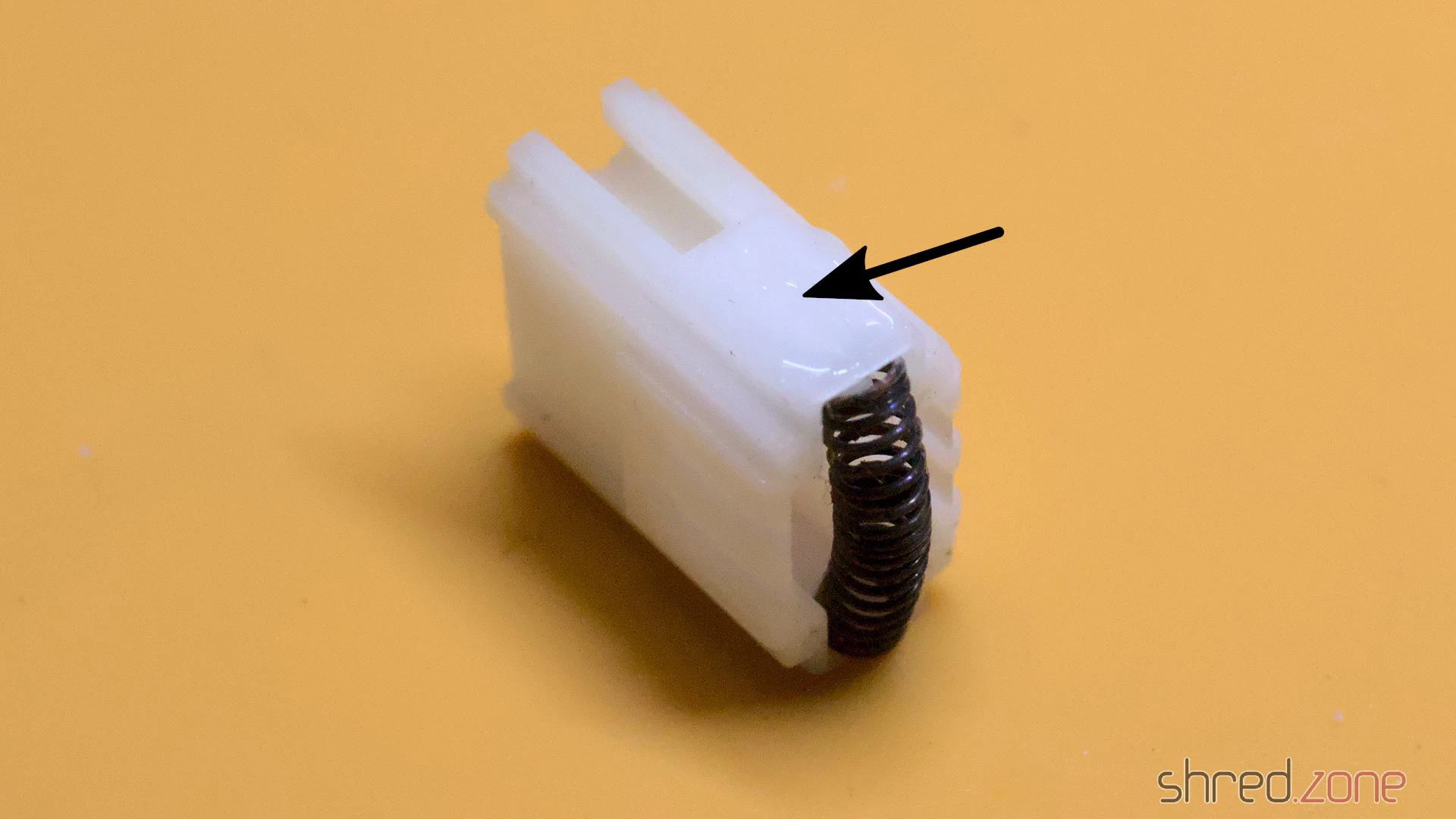
After that, the switch was reassembled and tested again. If it was still getting stuck or didn’t close the contact properly, the process was repeated.
It was a lot of work and a monotonous task, but at the end I could make all the switches work again.
Whitening
The keyboard case was cleaned in soap water. After that, the case (and the yellowed space bar) were exposed to the July sun for whitening.
The result is quite good, but on some parts a bit of yellow is still visible. I guess there would be an even better result if I would use peroxide, but I have no experience with that, and am not too keen to gain it with this rare keyboard.
The labels on some of the keys are still yellow, and wouldn’t get any whiter in the sun. I guess that I will have to replace them with new labels some day.
Reassembling
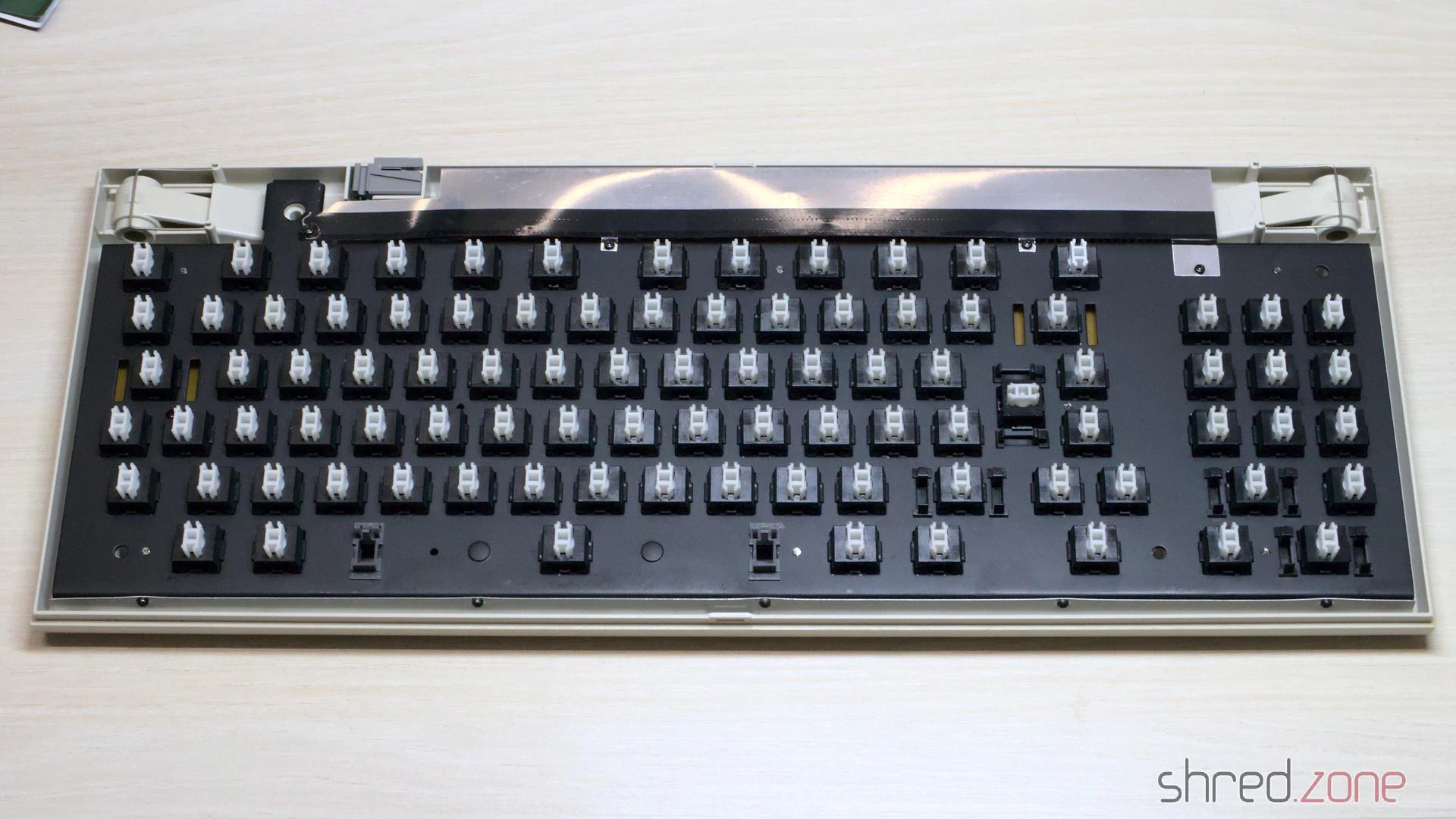
With every parts cleaned and whitened, the keyboard was ready for reassembly. I pressed the key caps back on the keys, mounted the shielding, and then put the keyboard frame back into the case.
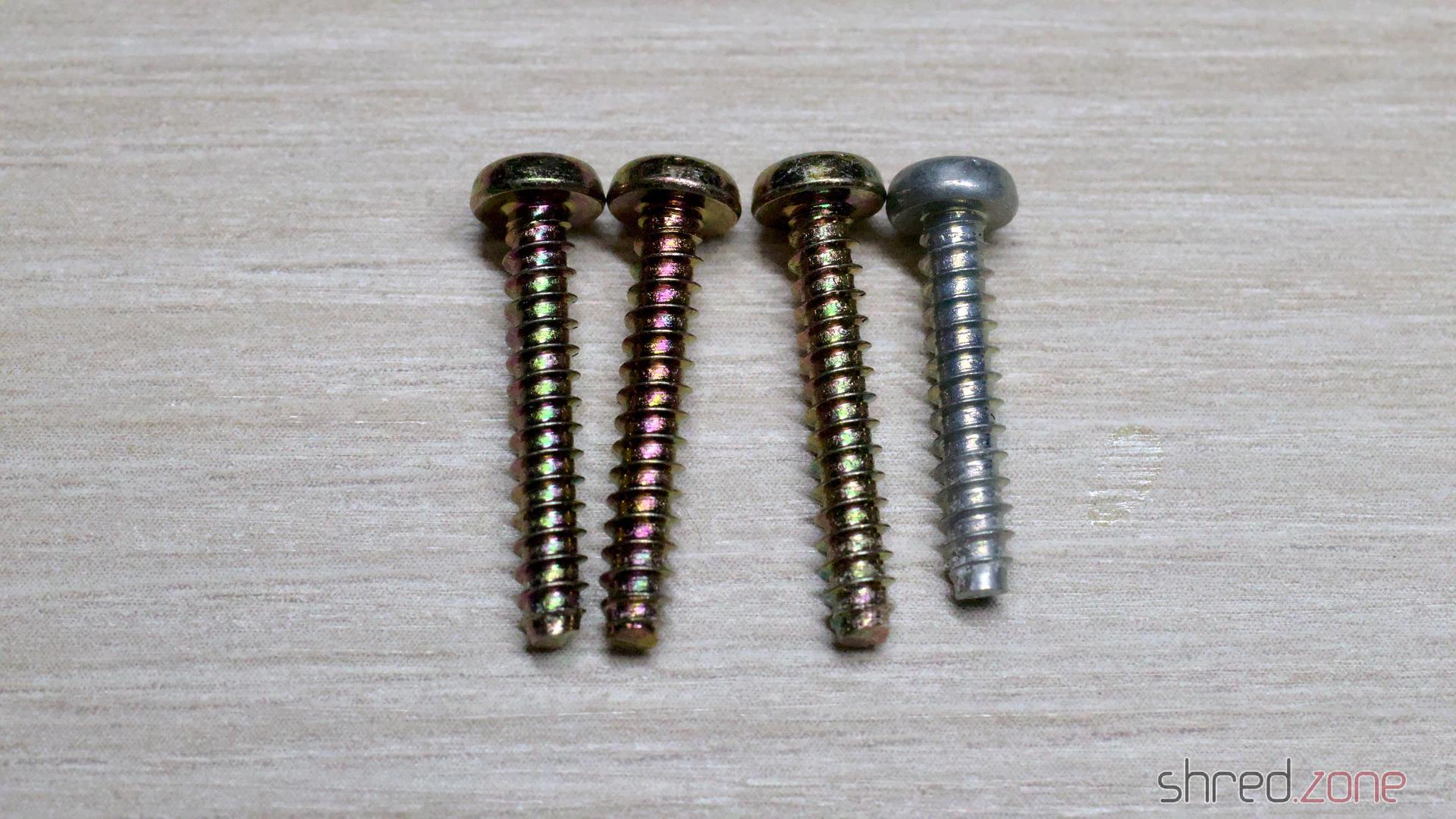
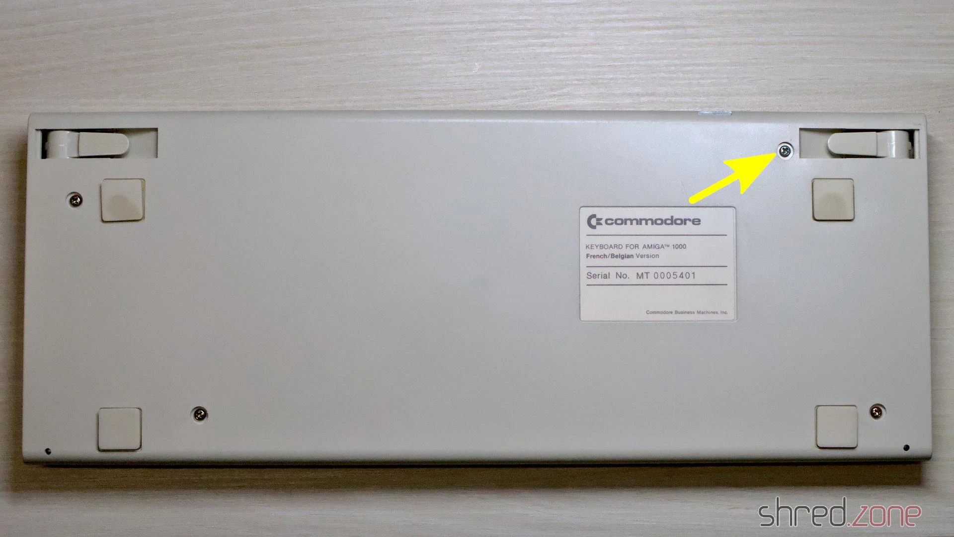
Take care when closing the case: One of the four screws is a bit shorter, and maybe also has a different color. This single screw must be used for the upper right hole.
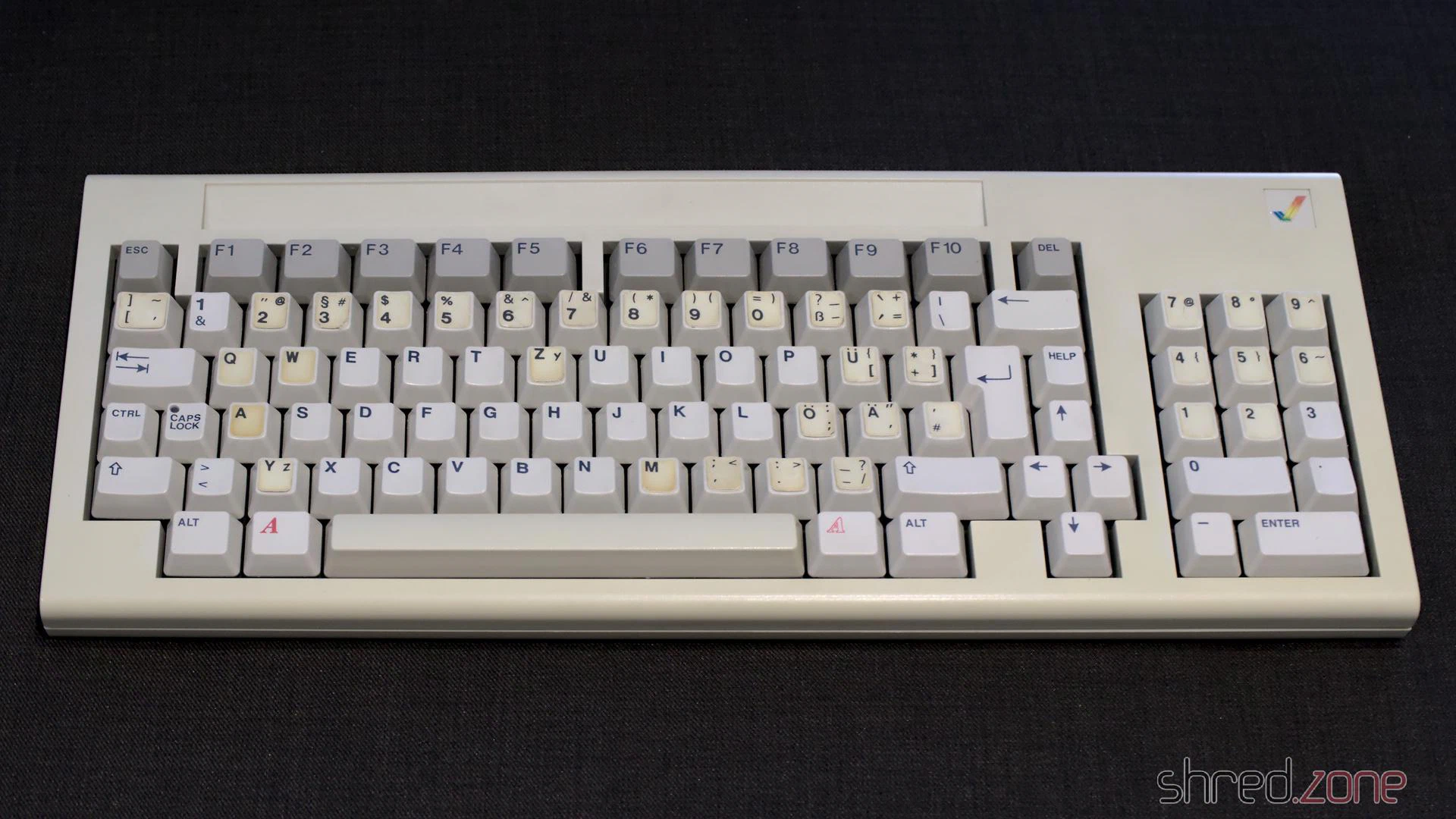
The keyboard restauration is completed now!
In the next part, I will reassemble the main unit, and have a first test. Is the Amiga still working?