 I haven’t forgotten about you. Some private stuff kept me from completing this project for a while. To make it up, I have added OpenSCAD files for a 3D printed case.
The controller was a little tricky to complete, mostly because of the very different component heights. I decided to use two circuit boards that are stacked onto each other by headers.
On the upper board, there are only the two buttons and the LCD, as well as the transistor and resistor for the LCD backlight. As I only used one-layer TriPad strip boards, I had to use this one upside down for the male headers to point downward. This rather unconventional use made it a little tricky to solder the buttons and LCD headers on the actual bottom side of the board.
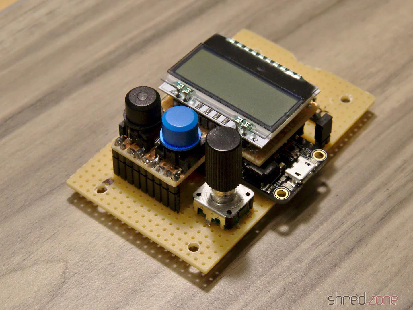 The lower board contains all the other components, as well as the wiring. The rotary encoder also made it to the lower board, because it is much taller than the other buttons. This way, the top of the button caps are almost level and nice to look at.
The result is surprisingly compact for a DIY solution. The button caps and the LCD are just perfectly positioned for a case.
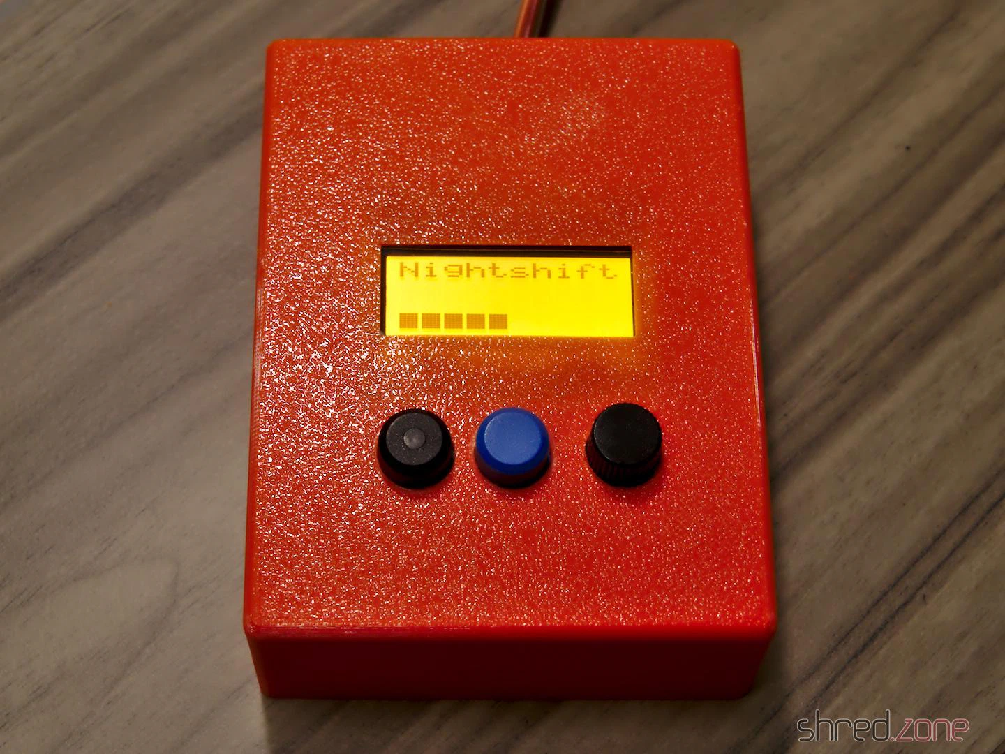
With plastic feet attached, you can use the controller as it is. You can also get a plastic case with transparent top, drill three holes in it for the button caps, and mount the sandwich with spacers. But if you have the chance, you should definitely go for a 3D printed case.
I have set up a project at Codeberg. It contains the circuit diagram, the bill of materials, the firmware source code, and OpenSCAD files for a printed case. There is no firmware binary yet, as you need to adapt the source code to the length of your LED strip anyway.
 There are bonus OpenSCAD files in the project, for printing a customized case. Due to the absence of properly layouted PCBs, I am aware that each controller is going to look differently when finished. In the
 parameter.scad file, you can change all kind of parameters, so you should be able to make your individual case in, well, almost any case (silly pun intended). 😄
The SPI flash memory of the Feather M0 Express is not used yet. In a future release, I may add a settings menu for the LED strip size. The controller is also forgetting all its settings when disconnected from the power. This needs to be addressed in a future release as well.
But after all, this is a start for your own DIY wall bias lighting. Feel free to send pull requests for enhancements!
Again, remember that you must remove the jumper before connecting the Feather to an USB port, otherwise your computer will be damaged.
 In the first part, I have assembled a working proof-of-concept for my premium wall bias lighting. Thanks to CircuitPython, it just took a couple of minutes to program a light effect once the hardware was working.
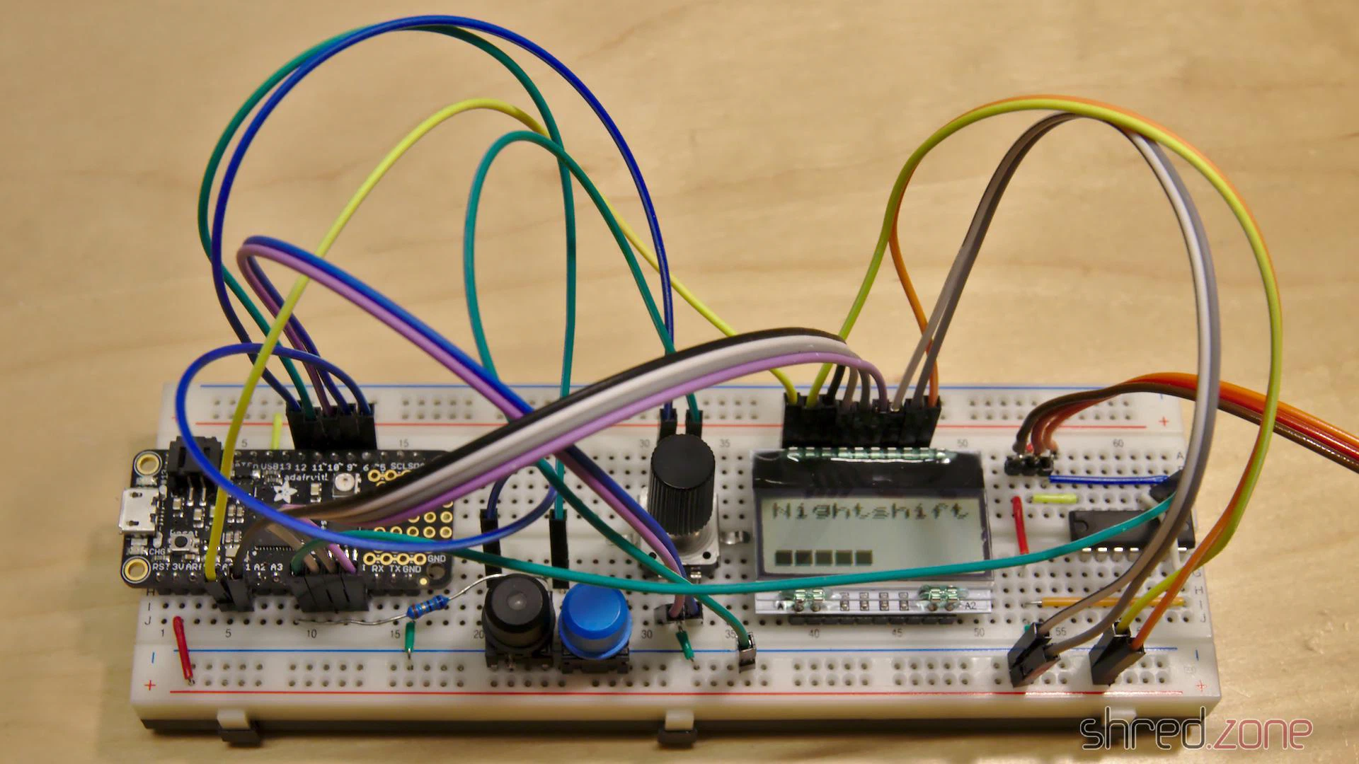
Now it’s time to extend the hardware to its final stage. I’d like to have a LC display that shows the current settings. A button and a rotary encoder allows to browse through different menus and change the parameters. And finally, the strip shall be switched on and off by an illuminated power button.
Thanks to the bread board, the components were quickly added and connected to the Feather with some wires. Polling the buttons is a basic functionality of CircuitPython. It was also incredibly easy to poll the rotary encoder, because CircuitPython already comes with a library for that.
It took a lot more time to set up the LC display. CircuitPython supports SPI out of the box, but the SSD1803A controller of the display uses a weird protocol. Each command byte must be split up into two nibbles (4 bits), which are packed into bytes again, with the bit order reversed. The SPI library does not offer support for it, so I had to do all this bit mangling in Python, which turned out to become a rather ugly piece of code.
But then, finally, a minimal version of the firmware was working. I could turn the light on and off, select between two light effects, and I could also control the brightness.
However the Feather often took long breaks, where it did not react on key presses for multiple seconds. I guess the reason for that is Python’s garbage collector, which stops the world while it is collecting unused objects and freeing some memory. This was actually a pretty annoying behavior that rendered the controller unusable.
After I added a third light effect, I also started to run into frequent out of memory errors. It seems that I have reached the limits of what is technically possible with CircuitPython on a Feather.
Was my approach too ambitious?
Luckily it wasn’t. The Feather can also be programmed in C++, using the well known Arduino IDE. It comes with a lot of libraries that are ready to use. It’s all very lightweight and is looking very promising. So why did I use Python in first place? Well, it is because I wrote my last lines of C++ code about 20 years ago. 😅
Porting the existing Python code to C++ was easier than I had expected. The SPI library now even supports reversed bit order, so it was much easier to address the LC display. On the down side, I had to test several libraries until I found a reliable one for the rotary encoder.
The C++ code consumes a fraction of the Python code’s memory, so there is a lot left for extensions. The garbage collection breaks are also gone now, so the controller instantly responds to key presses. And I haven’t even used the Feather’s SPI flash memory yet. 😀
I have added some more light effects, and menus for adjusting brightness, saturation, and color temperature. Everything is working as expected now. It’s time to finish the prototype phase and draw a circuit diagram.
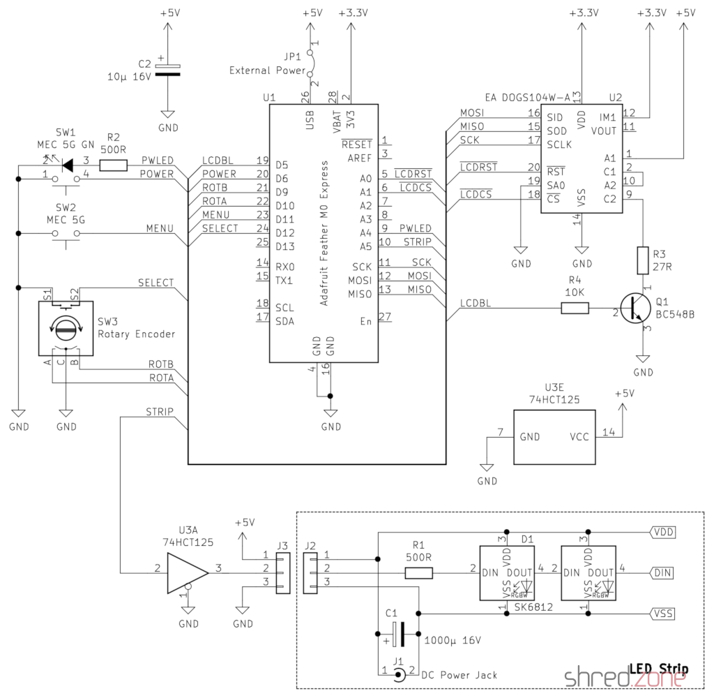
R2 is the series resistor for the power button LED. A green LED would need an 68 Ω resistor at 3.3 V. However the LED is directly connected to the Feather, so the current should not exceed 7 mA (maximum rating is 10 mA). A 500 Ω resistor limits the current to a safe value. If you need more current for a fancy power LED, you can use one of the three 74HCT125 drivers left, or add a transistor.
R3 is the series resistor for the LCD backlight. The manufacturer specifies a 27 Ω resistor when the backlight LEDs are connected in series and powered with 5 V. If you use a different backlight, change the resistor accordingly. The BC 548 transistor permits up to 100 mA in this configuration.
Remember: You must remove the jumper JP1 before connecting the Feather to an USB port, or your computer will be damaged.
In the next part, I’m going to grab my soldering iron and build a final version. It’s high time. The many wires on the breadboard prototype are annoying when operating the rotary encoder. Also its pins are too short and are often disconnecting from the breadboard when I use it.
 A good way to relieve the strain from your eyes while working on a PC, is to illuminate the wall behind your monitor. Jason Fitzpatrick wrote an interesting article about what bias lighting is and why you should be using it.
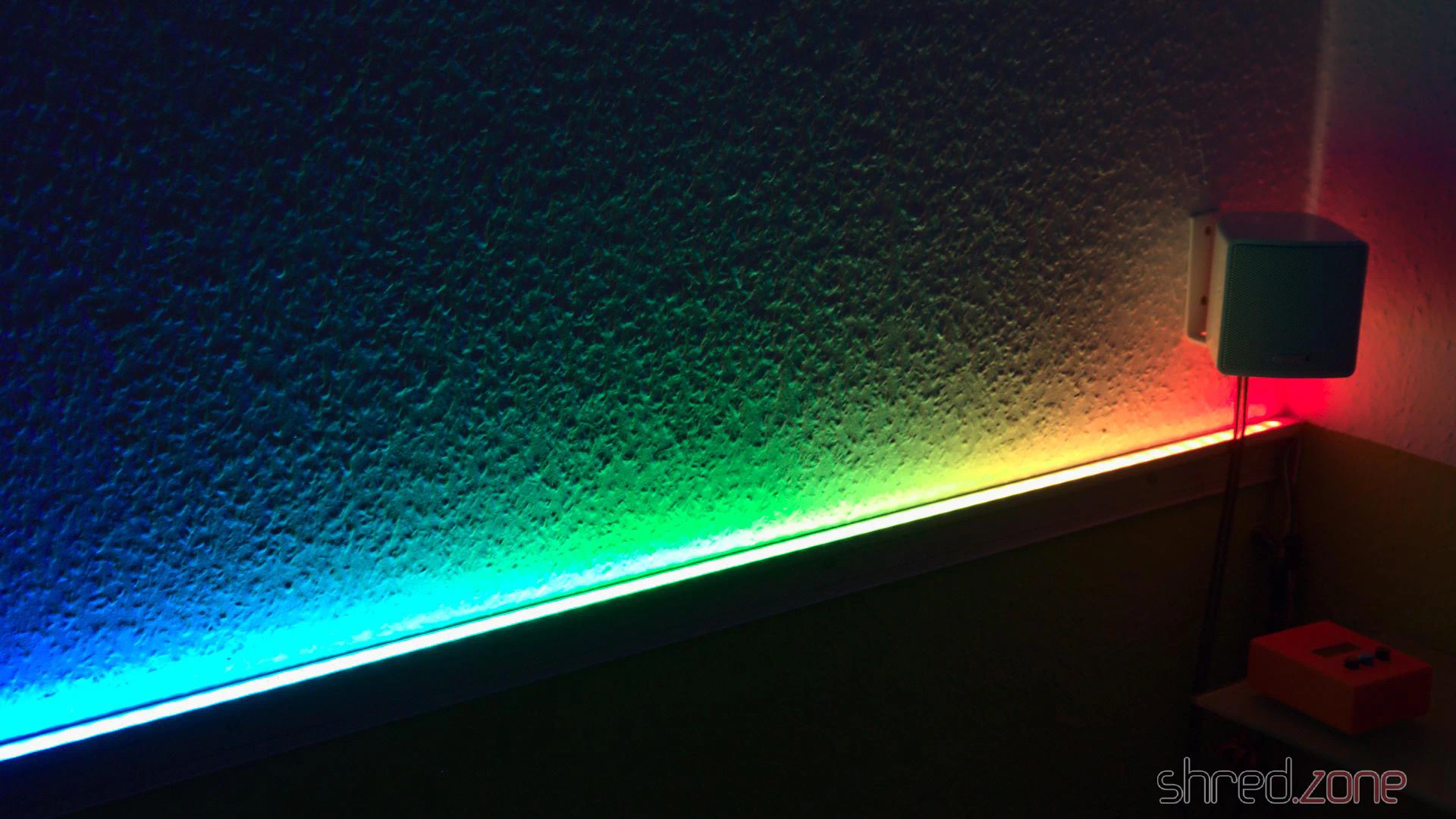
Many light sources can be used as bias lighting. I have used an old bedside lamp for a while. But what about something more stylish? What about a LED strip on an aluminum profile?
In this project, I am going to make a Wall Bias Lighting myself, and write a controller software for it. The source code will be released on my Codeberg profile eventually, so you will be able to customize it.
Proof of Concept
To make it a true premium lighting, I use a LED strip that consists of SK6812 RGBW LEDs. It can produce colors, but it also has separate white LEDs for a clean neutral white. Even better: Each LED can be addressed and the color changed individually. It would be possible to illuminate the wall behind the monitor in a bright white, while the visible parts of the strip are in a soft blue that won’t dazzle the eyes.
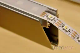
AdaFruit sells these LED strips under their brand name NeoPixel, but there are also no-name strips on the market that are fully compatible and considerably cheaper. The strips are usually sold on reels of up to 5 meters length. They can be shortened to the desired size with scissors, and have an adhesive tape on the back so they can be glued to aluminum profiles.
This is the bill of material for the first proof-of-concept phase of the project:
- An SK6812 RGBW LED strip with 60 LEDs per meter
- An aluminum wall profile for LED strips
- 1x AdaFruit Feather M0 Express
- 1x Level converter (read below)
- 1x 1000 µF/16 V capacitor, 1x 500 Ω resistor (read here why they are needed)
- 1x 5 V power brick. Each LED is said to consume up to 60 mA (I couldn’t find concrete figures), so you will need 18 W per strip meter if you want to set all four colors of all LEDs to maximum brightness.
The assembly was rather simple. First I cut the profile and the strip to the desired length and glued them together. Then I connected the strip to the power supply, and the strip’s data line to the Feather via the level converter.
The next thing on the to-do list was a quick test drive, to check if some of the LEDs are defective. So I installed CircuitPython on the Feather, and wrote a tiny test program that just cycles through the colors red, green, blue, and white. With this pattern, even a single defective LED would immediately catch one’s eye.
I turned on the power supply, aaaand… Nothing! 😲 All the LEDs stayed black.
I checked and double checked the wiring, but everything seemed to be correct. I tested my test program on the single NeoPixel that is mounted on the Feather, and it worked there.
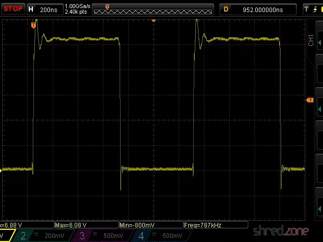
Puzzled, I connected my scope to the data line of the LED strip. It immediately revealed the culprit.
The Feather runs on 3.3 V, and so the signal on the data line has an amplitude of 3.3 V.
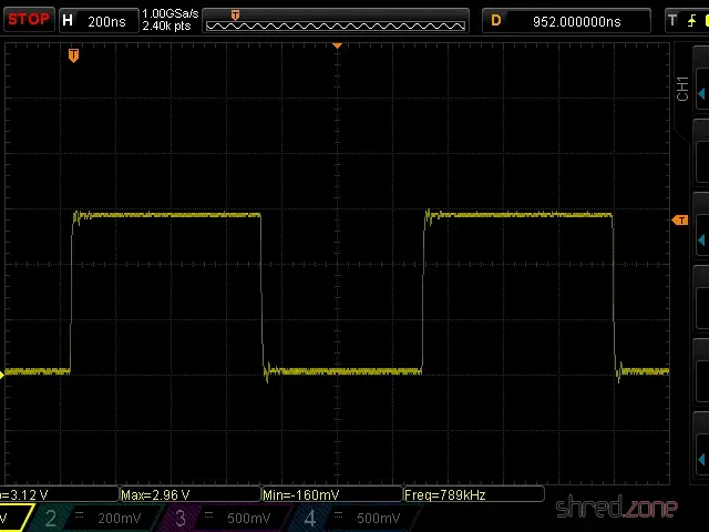
The LED strip runs on 5 V though, and also expects a signal amplitude of 5 V. The logic converter between the Feather and the strip is supposed to convert the 3.3 V signal to 5 V. However, the BSS138 based bi-directional logic level converter from my spare part box turned out to be too slow for this purpose. The output level starts at 3 V and then ramps up to 4 V.
This is not sufficient for the SK6812, which needs a 5 V signal and a very precise timing with clean signal edges. Both was not given, so the LEDs stayed black.
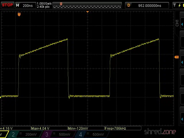
I replaced the logic level converter by a standard 74HCT125 buffer IC, and tried again. The LED strip immediately came to life and cycled through the colors. The scope now shows a clean (well, more or less clean) 5 V signal.
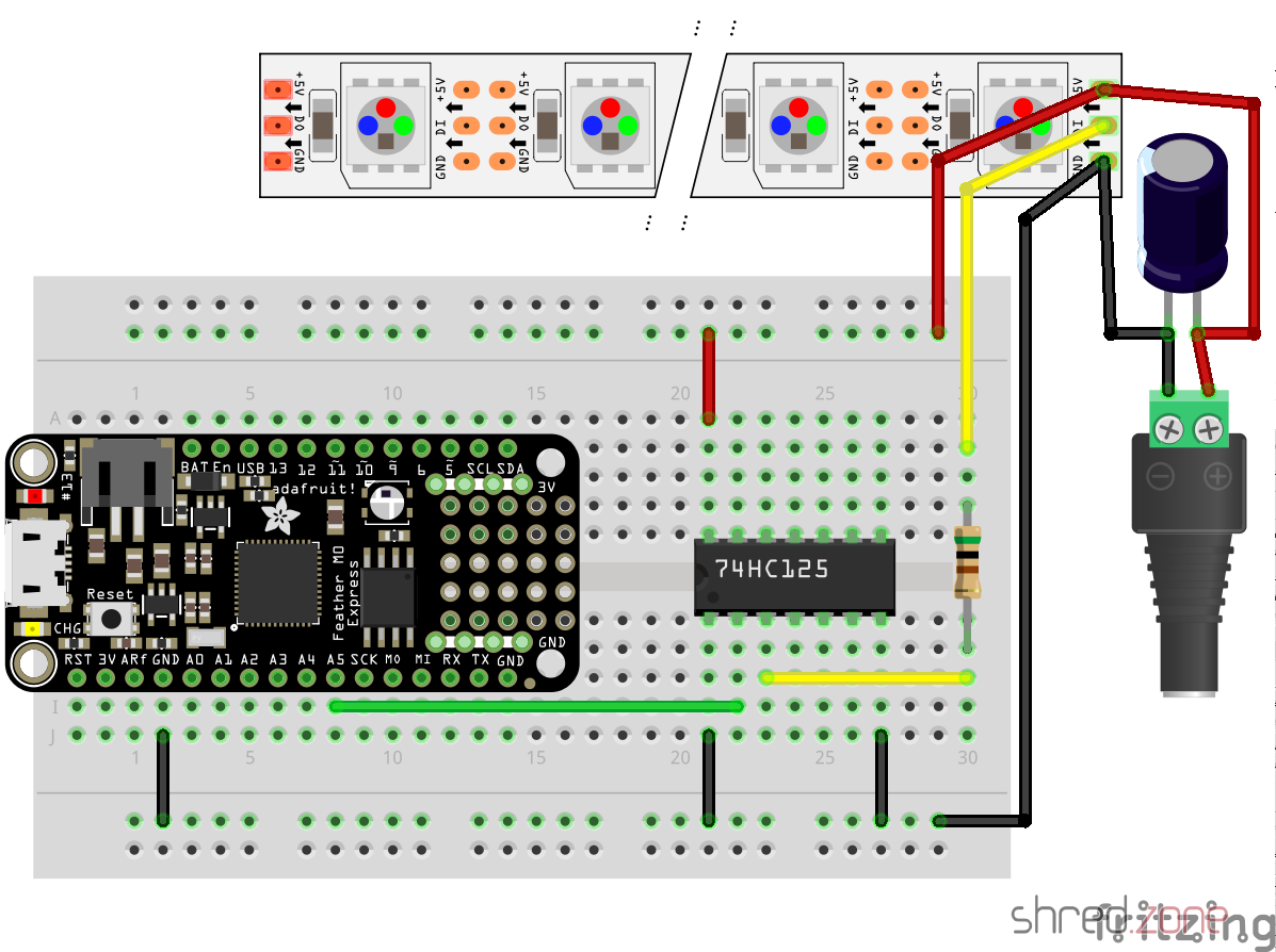
My proof-of-concept is working. 🎉 This is what the circuit looks like:
While the LED strip is powered by the power brick, the Feather is going to be powered by USB as long as I am developing the software. Later I will also supply the Feather with LED power, so it runs stand-alone.
Never connect the Feather to an USB port while it is supplied by an external power source. It could damage your computer.
What next? I’m going to add a power button, so I can turn the light on and off. For controlling the brightness and light effects, I am also going to add a display, a rotary switch, and another button. Stay tuned…
 A simple method to keep burglars away from your home is a TV simulator. It’s basically a device with some bright RGB LEDs showing color patterns that resemble those of a telly turned on. They are sold at many electronic retailers. However, some customer reviews say that the color patterns do not look very realistic, with some distinctive flashes and colors that are usually not to be seen on a regular movie. Besides that, the color patterns often repeat after about half an hour.
Actually, distinctive color patterns that repeat after a short time, are a major disadvantage. Experienced burglars might recognize the color patterns and figure out it’s a TV simulator. This would rather be an invitation than a deterrent.
So, let’s build a better TV simulator ourselves. It’s also more fun than buying something ready.
The Idea
What do we actually see when we watch a telly from outside a room? Usually there are colors with a medium saturation, changing slowly while the actors move or the camera pans. And there are very few hard cuts in the hue or brightness when the scene changes, when there is an explosion in an action movie, or something like that.
We could simulate these effects randomly, but what would look more realistic than using a real movie as a source? The idea is to squeeze a real movie stream into a sequence of RGB colors that are small enough to fit into an Arduino Uno with just 32 KByte of flash space.
You say that’s impossible? It isn’t! 😁
The Ingredients
I used the following parts for the TV simulator. They are rather cheap and can be purchased in many electronic shops:
- Arduino Uno
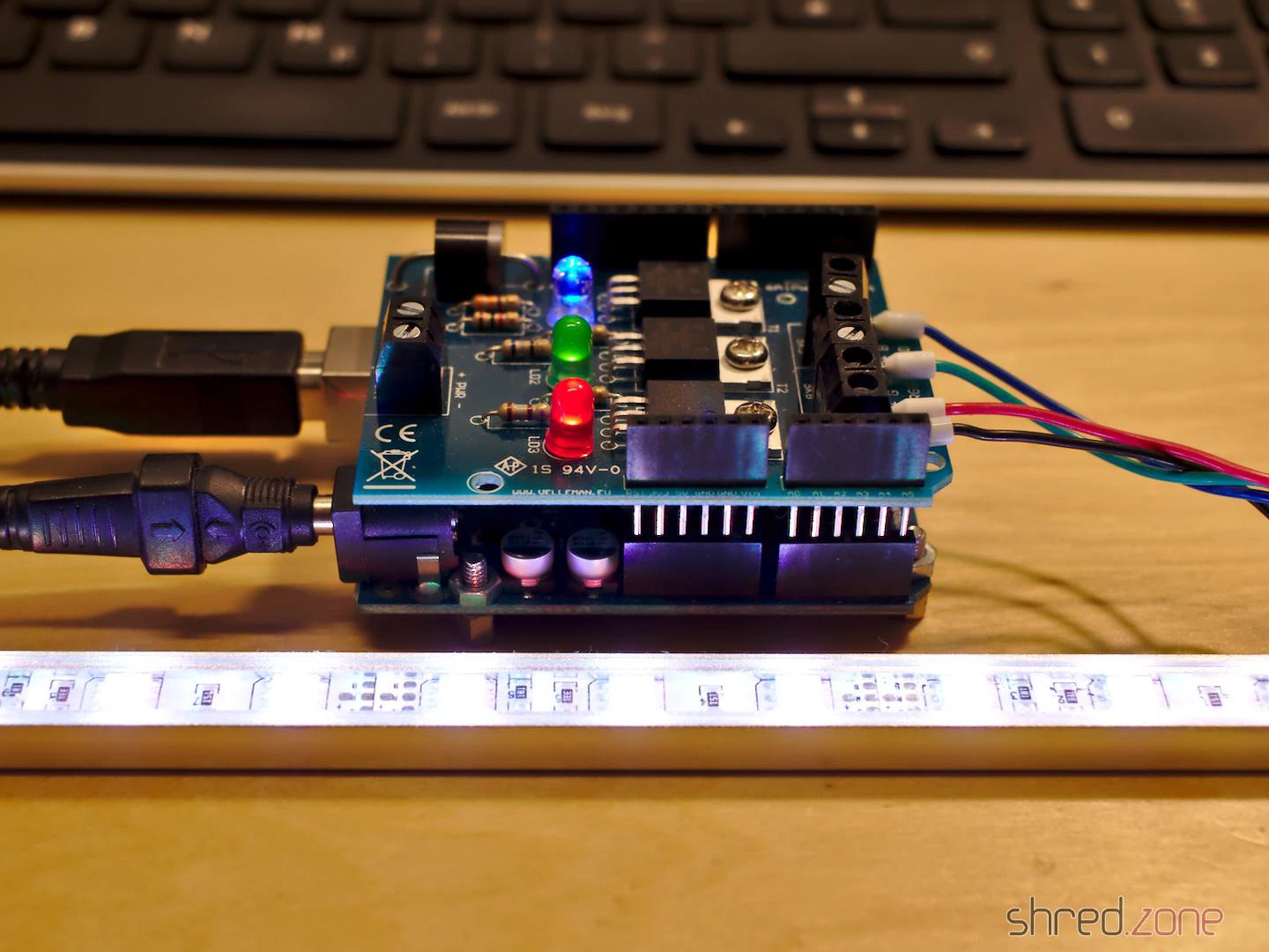
- Velleman KA01 RGB shield. Any other RGB shield or a self-made solution should work as well, maybe with some minor modifications to the code.
- RGB LED strip (12 V, about 7 W, Common Anode)
- 12 V wall power supply for supplying the Arduino and the RGB LED strip (1 A or more)
Now just connect the RGB shield to the Arduino, and connect the LED strip to the RGB shield. That’s all, hardware-wise.
Caution: The RGB LED strip is a very intense light source that can cause permanent damage to your eyes! Avoid looking directly into the LEDs!
The Software
You can find the source codes of the Arduino sketch and the movie converter in my Codeberg repository.
The movie converter is written in Python and uses OpenCV. Basically, it converts an mpeg stream to a source code that can be included in the Arduino sketch. But there are also a few parameters you can toy around with to improve the result.
The next step is to compile the sketch and upload it to the Arduino. The movie should start playing back immediately.
Actually, the encoding is so efficient that you can cram a full-featured movie of 2 hours into the tiny Arduino memory.
Behind the Curtains
How does the converter work? And why is it so efficient?
First of all, as nobody is going to actually watch the simulated movie, we can remove the audio tracks and drastically reduce the frame rate. 10 frames per second is the default, but if the Arduino memory is too small for your movie, you can even go down to 5 frames per second.
Also, unlike a real TV, the RGB shield is only able to generate a single color, so all we need is the movie as a stream that is scaled down to a single pixel.
The converter software now analyzes the single-pixel movie stream. For soft color changes (like fixed camera positions or slow camera pans), it only stores the target color and the time it takes to reach it. When playing back, the Arduino will just gradientally change from the current color to the target color in the given time. For hard color changes (like jump cuts or in action scenes), the change to the target color will happen immediately.
Movies mostly have soft color changes, and only a few hard changes, so several seconds of video material can be stuffed into just a few bytes. This is why the converter is so efficient.
The algorithm is pretty simple, but gives amazingly good results. Especially on action movies, with a lot of cuts and striking action scenes.
The luftdaten.info project offers a build guide for a fine dust sensor. It’s cheap and easy to put together even with little electronics knowledge. You can get the parts in various electronics shops and nowadays even on Amazon.
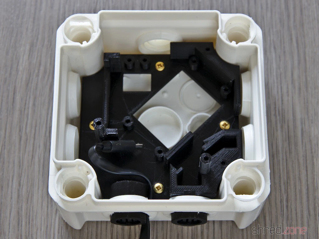
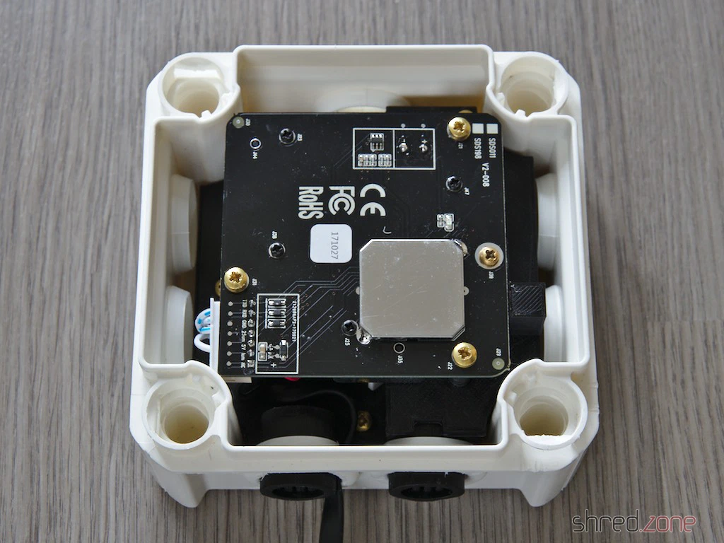
The original kit uses two plastic pipes as a casing. They’re cheap and easy to get in any DIY store, but they don’t look particularly great. I chose a standard UV and weatherproof outdoor junction box as the casing instead. A custom-designed 3D-printed frame is placed inside, and the electronics are mounted on it.
The frame already has a wind tunnel for the drawn-in air, so unlike the original instructions, you don’t need a hose. Grids in front of the air vents stop insects from crawling into the case. Also, unlike some other printed solutions, the fine dust sensor is aligned as specified by the manufacturer, and the intake hole is protected from light.
Unlike the original guide, though, you can’t avoid picking up a soldering iron here.
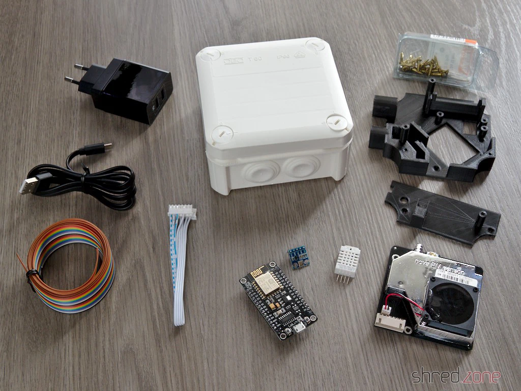
You’ll need the following parts:
- 1x set of 3D-printed frame parts
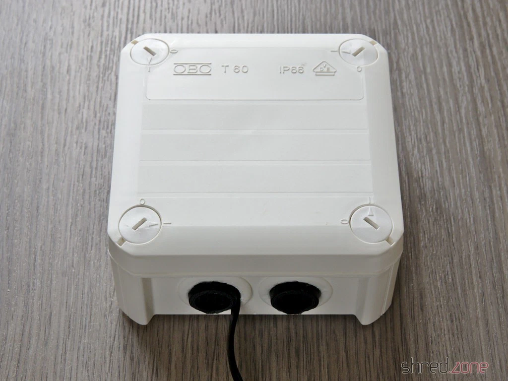
- 1x OBO Bettermann T60 junction box with plug-in seals
- 1x NodeMCU ESP8266 (by Lolin, other brands might not fit)
- 1x ILS-Nova SDS011 fine dust sensor
- 1x DHT22 temperature and humidity sensor (usually optional, but required here as it seals off a hole in the wind tunnel)
- 1x BMP180 temperature and air pressure sensor (optional)
- 11x wood screws 3.0 x 12 mm
- 4x wood screws 3.5 x 12 mm (or four more 3.0 x 12 mm)
- A bit of ribbon cable
- Some heat shrink tubing
- USB cable (flat)
- USB power supply (an old mobile phone charger is absolutely fine, the sensor needs less than 200 mA)
You don’t need any particularly UV or weatherproof filament for the printed parts, since they’re protected by the junction box. The filament just shouldn’t be so brittle that the screws break it. And it should be as dark as possible so no stray light gets into the dust sensor’s opening. I used basic black PLA.
Important: The print should be done without supports, as they are really hard to remove afterwards and could block the air duct. The parts are designed so they can be printed with PLA even without supports.
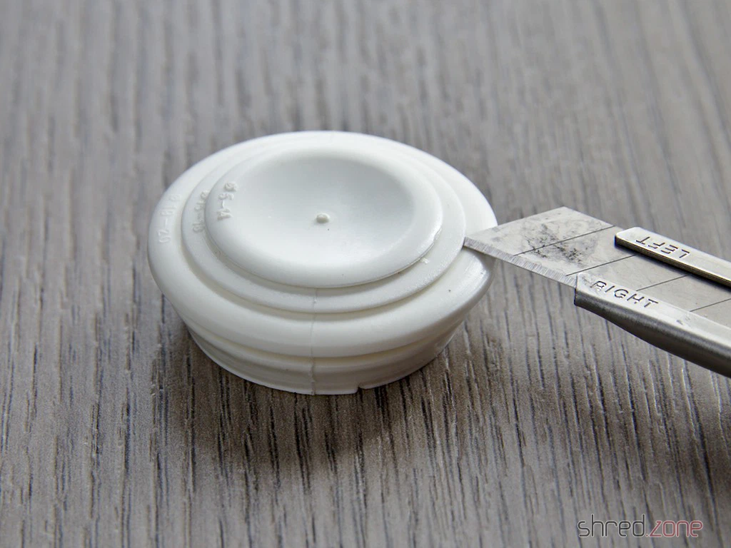
First off, remove the two plug-in seals from one side of the junction box and cut them open at a 19-20 mm diameter.
Now poke the USB cable through the left hole, then pop the lower support frame in from the inside and screw it down with the 3.5 x 12 mm screws. The casing can now be sealed up again with the plug-in seals.
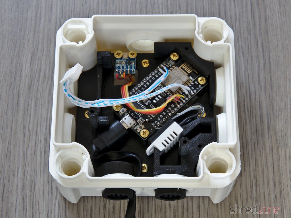
It’s time to solder the electronics together according to the guide. The pins of the DHT22 should be protected with the heat shrink tubing. How to wire up the optional BMP180 air pressure sensor is explained in the FAQ. It’s best to install the firmware now and do a test run. Once the device is put together, it might be trickier.
Screw the NodeMCU and the BMP180 onto the base plate and plug the USB cable in. Just slot the DHT22 into its designated spot in the wind tunnel (see photo), it doesn’t need to be screwed down.
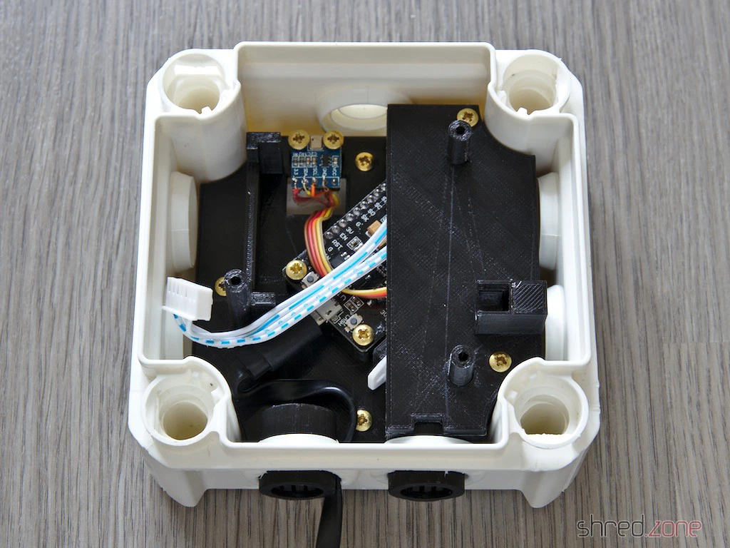
Next, pop the top plate on and screw it down. Connect the fine dust sensor, then carefully slide it into the air vent and screw it in place. You might need to snip a tiny bit off the plug to make it fit.
That’s it. You can pop the junction box lid on and secure it. The sensor is ready to go.
Mount the fully assembled sensor on an outside wall with the openings facing downwards. The casing should easily survive rain, snow, and hail. Since PLA goes soft at 60°C, you should avoid a spot in direct sunlight though. The sensor can also be operated lying flat, but the openings should be protected a bit from the rain then.
The sensor is powered via the USB cable. Since no data is transmitted, the cable can easily be several metres long.
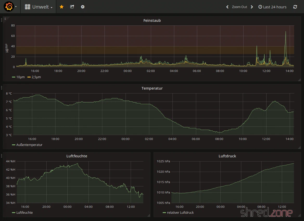
Once you’ve registered your sensor at luftdaten.info, you can see the measurement data on the map and download it as a CSV file. The current measurement data can also be queried directly via Wi-Fi in JSON format and stored in a database, for example. I use a little custom-programmed tool that fetches the data regularly, drops it into a PostgreSQL database, and displays it via Grafana.
Have fun tinkering! 😀