When the Amiga 1000 was launched in 1985, it was too expensive as a home computer, but rather targeted the professional graphics workstation market. The sales figures were correspondingly low. Only 27,500 units have been sold in Germany. Nevertheless, and without a doubt, the Amiga 1000 is the jewel of every Amiga collection. Now I finally had the lucky chance to get my own one.
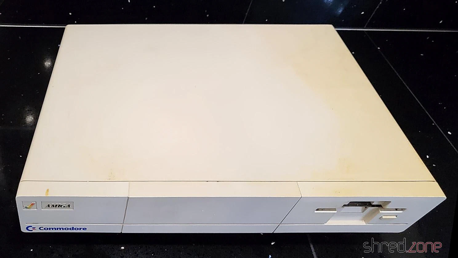
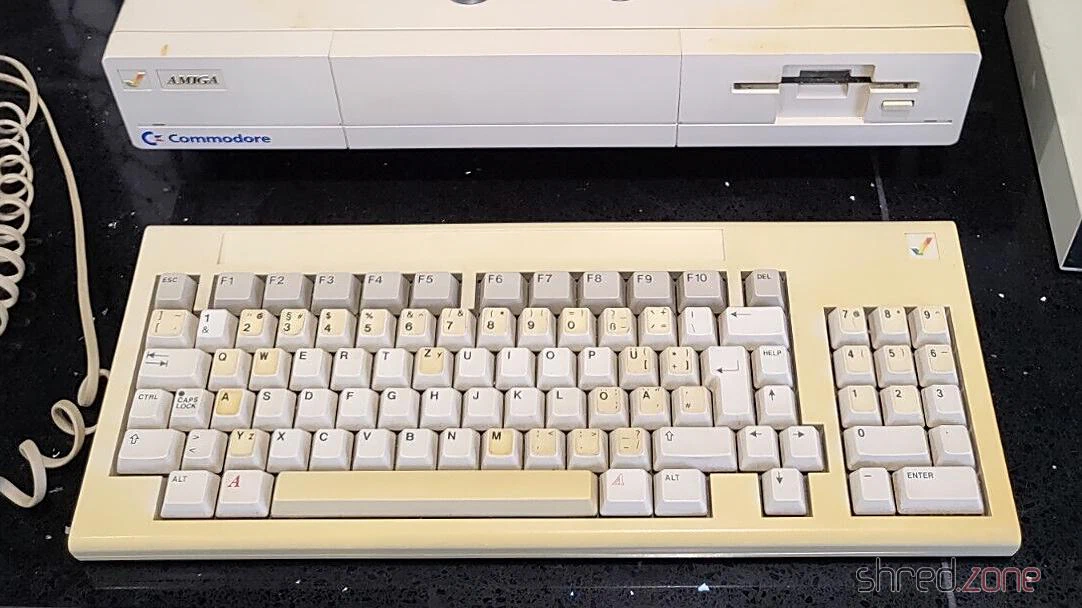
The overall state is fine, considering that the machine is almost 40 years old. The Amiga itself is only a bit yellowed, but has some heavy scratchmarks at one edge. The keyboard has a French/Belgian AZERTY layout that was changed to German layout using stickers, like it was usual for the first machines that were sold in the EU. Its case and the space bar are much more yellowed. The stickers are also yellowed, and one is missing.
The expansion slot at the front contains a 256KB RAM module. The original mouse and the disks have been lost, but I can use any other Amiga mouse and make new disks myself.
What’s Inside
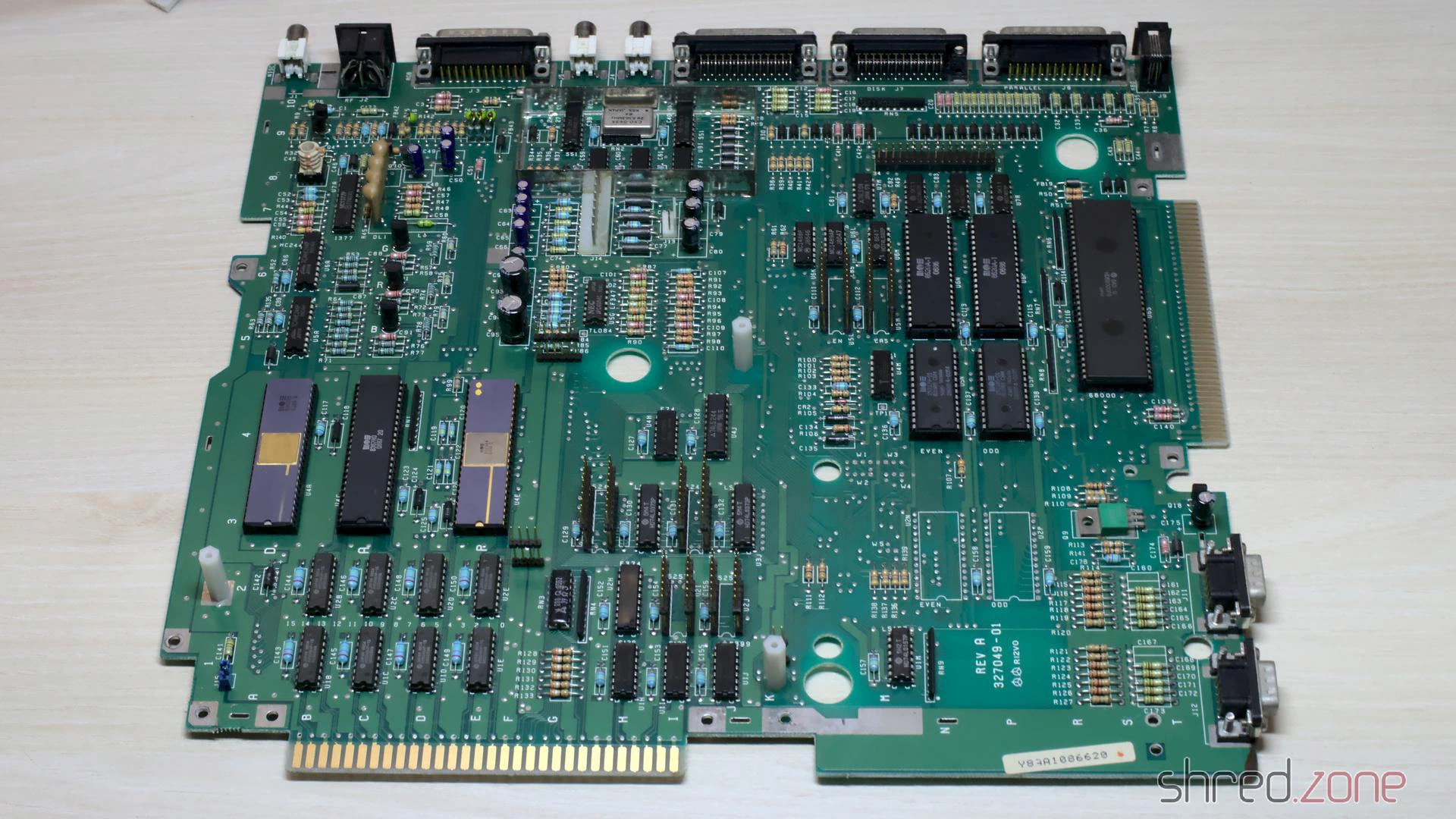
Inside I found a Rev A mainboard and a piggyback board. That extra board stores the Kickstart that is loaded from disk when the machine is powered up. Later revisions used Kickstart ROMs, and didn’t need this piggyback board any more.
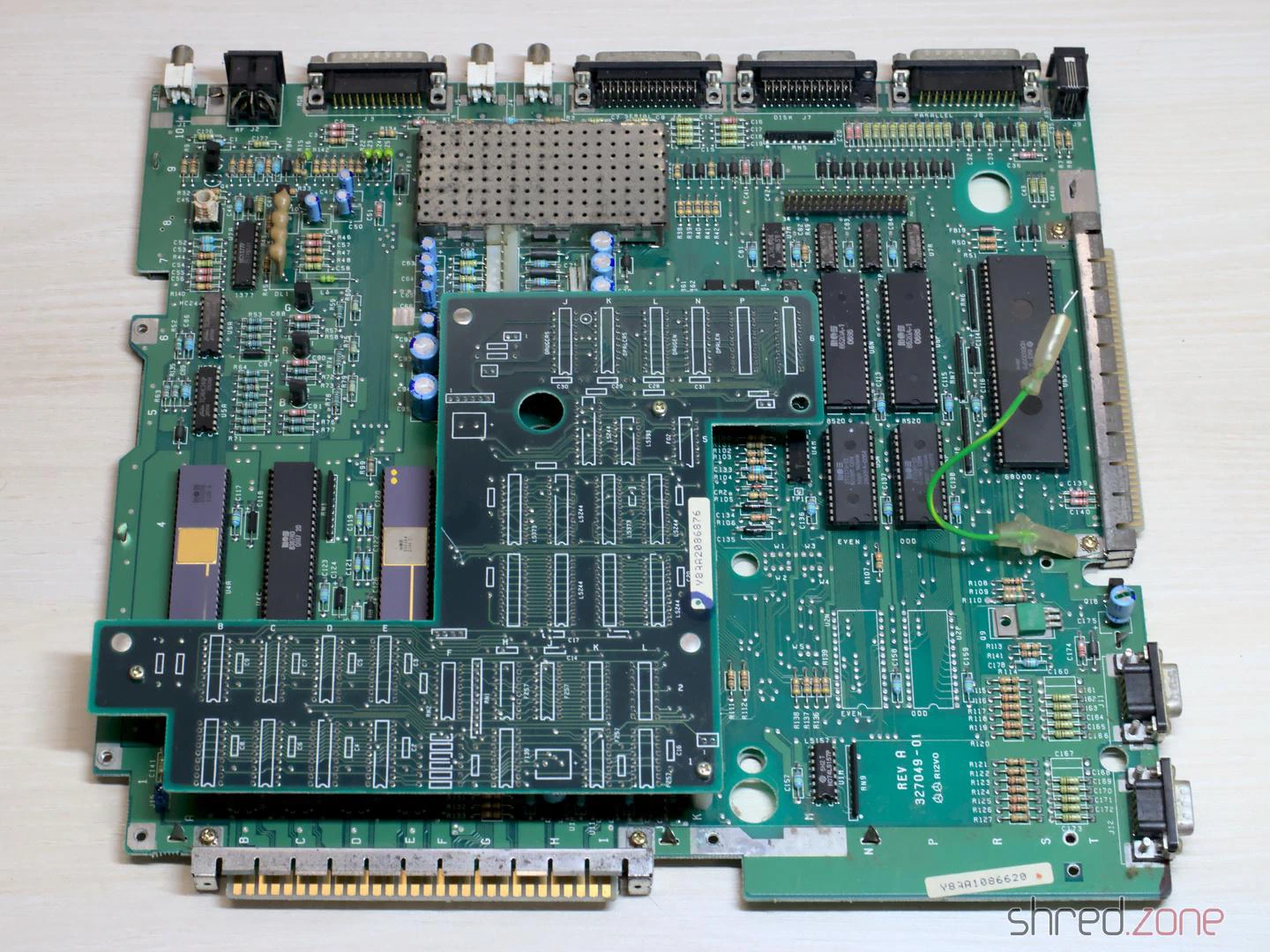
Usually all piggyback Amiga 1000 were produced for the US market. They could not run in Europe without modifications, due to different power frequencies and TV standards. My machine was produced in early 1986, presumably for the US market. One year later, it was modified for the European market. The original Agnus chip was replaced by a 8367R0 that is able to generate PAL video signals. The crystal is still the original 28.6363 MHz NTSC one though, so the video signal is not truly PAL.
The system has a Denise 8362R6, which is the first revision that is also capable of displaying the Extra Halfbrite mode.
Altogether, it is an early Amiga model, and very likely one of the first that have been sold in Germany.
The PSU
Generally I don’t recommend to power up an old computer straight away after many years of storage. Without a visual inspection and the necessary refurbishment, the power supply could damage the computer, or components inside could blow up.
A first visual check of the PSU seemed to be allright, with no obvious damages, and no bulged or leaked capacitors. But then I found tiny cracks in one safety capacitor.
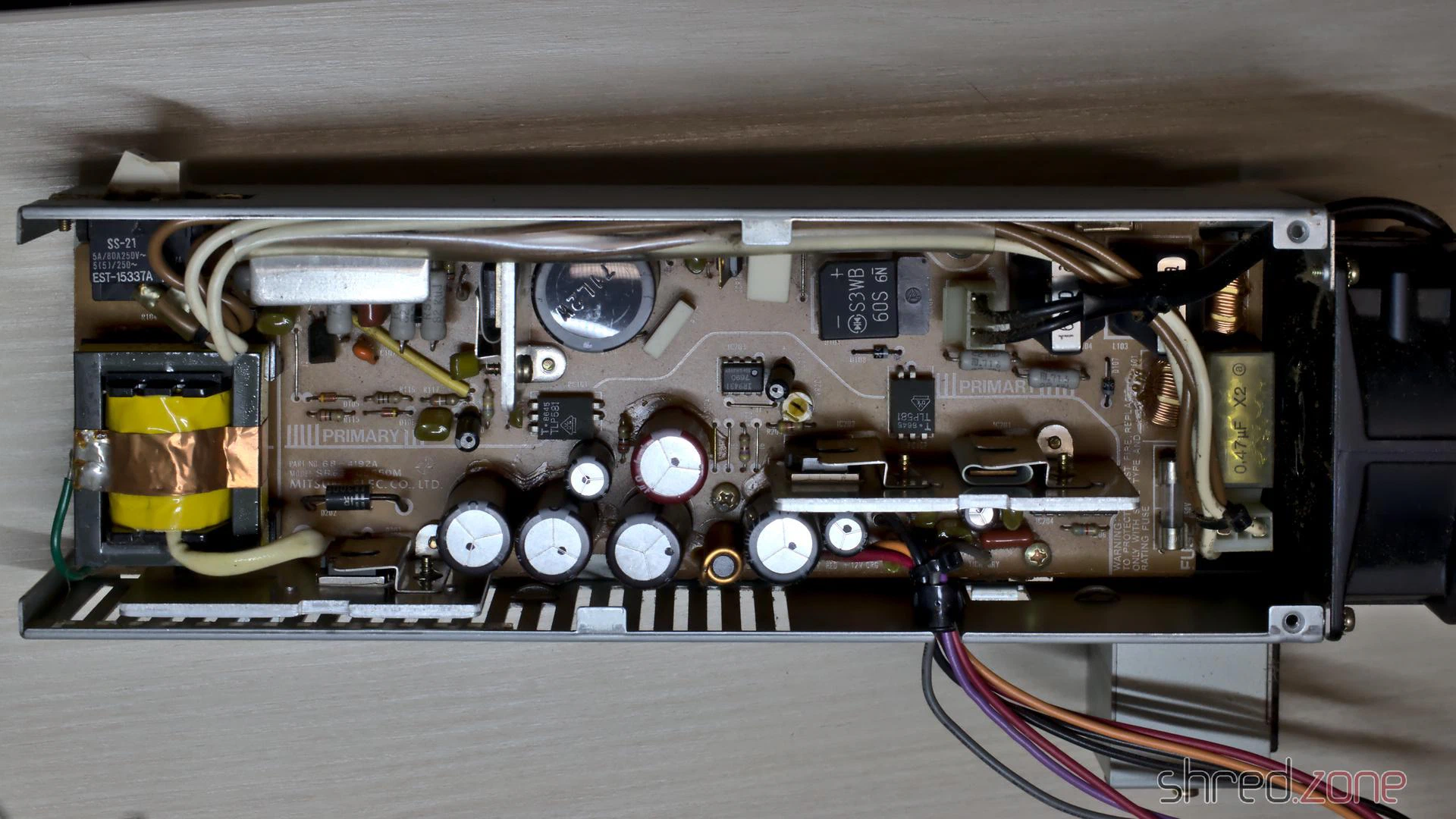
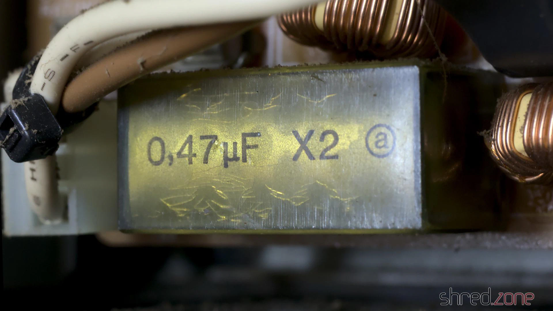
These RIFA X class capacitors are actually infamous for blowing up after many years. Their insulators are made from paper. The material gets brittle from age and thermal stress, letting in moisture, which amplifies the problem. Eventually the capacitor can crack open and go up in fumes.
It was good that I kept the PSU disconnected from mains. It is now being refurbished by @DingensCGN, a member of the A1K.org forum who has a lot of experience with Amiga PSU restauration.
The Mainboard
I recapped the mainboard and piggyback board. For the seven 22µF capacitors, I used a bipolar type instead. Those capacitors are used for filtering the audio and RGB signals. Using bipolar caps here might improve the signal quality, and won’t hurt otherwise.
To be honest, this time I had doubt if I should replace the old capacitors. This Amiga 1000 will not become a workstation, I have other Amigas for that. It is rather a collectible. Still I want it to be in a good technical condition. When I started to collect retro computers, I promised myself not to keep machines that are broken or otherwise not fit for use.
After that I removed all the dust, and gave the boards a thorough wash with IPA.
The mainboard is now ready to get remarried with the piggyback board, and then move back into the case.
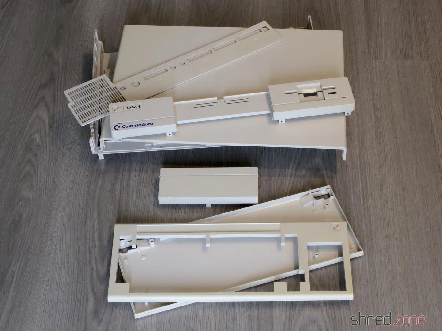
Whitening
The first thing I actually did was to disassemble the entire machine. The plastic parts of the case were cleaned in soap water and carefully scrubbed with a dishwashing brush. After that, I used the sunny July weather, and whitened all parts in the sunshine. I did not use any chemicals, just the sun. After two days, the Amiga was almost white again.
That’s it for the first part of the Amiga 1000 story. The next part will be about the restauration of the keyboard. There is a lot to do there.
 In the mid 1990s, MacroSystem Germany released the Maestro Professional sound card for the Amiga. It was a special sound card because it was fully digital, having only optical and coaxial digital connectors. It was suited for lossless recording from CD and DAT, as well as generating lossless audio output for DAT recordings. With tools like Samplitude, the Amiga became a studio quality digital audio workstation. There was also a tool for doing backups on DAT. At that time, these tapes were the cheapest way to backup entire harddisks (a 90 minutes DAT tape could backup almost 1 GB of data, which was a lot in the 1990s).
Unfortunately MacroSystem had never released a driver for the sound card, so it could only be used by a few (and mostly commerical) tools. I pestered their developers at every Amiga fair I could attend, but to no avail. Then, at the end of 1994, I decided to find the datasheets of the Yamaha chips, reverse engineer the board design, and write a driver myself. It took some time of trial and error, but eventually I was successful. In the coming years, my driver, the maestix.library (source code), became the inofficial standard driver. OctaMed Professional is maybe the most prominent software using it. Some professional music artists used Amiga and OctaMED for their production, so maybe my driver was even used for recording the masters of some famous CDs? 😁
Digital Audio in a Nutshell
The MaestroPro is able to receive and transmit digital audio data, either in the S/P-DIF or AES-EBU standard. The former one is still widely used in home equipment today, while the latter one was rather common in studio equipment. Today’s standards permit different encodings and high sampling rates, but the MaestroPro could only read 2-channel 16-bit raw audio with sampling rates of either 48kHz (DAT), 44.1kHz (CD), or 32kHz (DAB).
Besides the raw audio data, the standard also transports Channel Status Bits (CSB) and User Data Bits (UDB). The CSB contain information like the used sampling rate and the copy prohibition state. The UDB are not standardized, and usually transport proprietary data between studio equipment.
Inside the Maestro
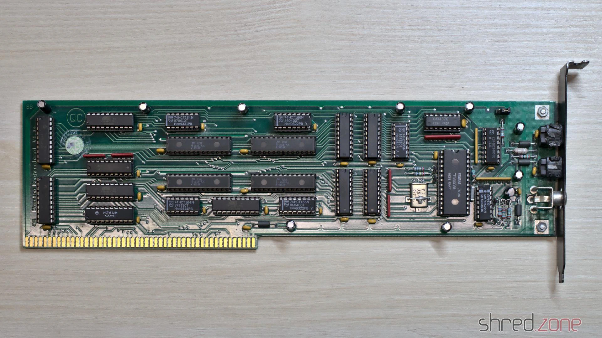
The board’s design is straightforward. It mainly contains a transmitter, a receiver, and FIFO memory for transporting the samples between the board and AmigaOS.
The optical and coaxial inputs go to a Yamaha YM3623B Digital Audio Interface Receiver (DIR). This chip decodes the audio data stream, extracts the CSB and UDB, and generates a raw bit stream of the audio samples. Shift registers convert it to a 16 bit parallel stream, which is stored in a 1K x 16 bit receiver FIFO. As soon as the FIFO is half filled, an interrupt is raised, and the Amiga driver reads the received data from the FIFO. This happens up to 190 times per second.
The most important CSB are readable via a status register of the board controller. The UDB are copied to a separate 8 bit shift register, which could be polled by the driver. However, UDB are usually 32 bit wide, so reading them was never really used in practice (at least not to my knowledge). The Maestix driver only provided a very rudimentary API for the UDB.
On the transmitter side, the 16 bit samples are pushed to a transmitter FIFO, and then converted to a serial bit stream by shift registers. A Yamaha YM3437C Digital Audio Interface Transmitter (DIT2) converts it to a digital audio stream and sends it via an optical output. The Maestro Pro does not have a coaxial output, presumably because there was not enough space on the board for a fourth connector.
The DIT2 is unable to generate the sampling rate clock by itself. It needs an external clock source instead. On the Maestro Pro, this clock is generated by the DIR. It is either derived from the bit stream of the selected input, or generated by an internal fixed 48kHz clock source. For this reason, the Maestro Pro needs to rely on external signal sources for 32kHz and 44.1kHz output sampling rates.
The transmitter can choose from two data sources. One source is the transmitter FIFO. The other source is the bit stream from the DIR, bypassing the FIFOs. This enables the board to modify the UDB and CSB of the incoming signal directly, without involving the CPU. But since the transmitter and reciver paths are fully separate, the MaestroPro is even capable of providing full-duplex audio streaming. The maestix.library takes advantage of that with the “realtime FX” feature, where the signal is read from the receiver FIFO, modified by the CPU, and then immediately sent back to the transmitter FIFO.
The entire board is controlled by three GALs and a small handful of 74LS logic chips. They take care of the Zorro bus protocol, provide mode and state registers, and orchestrate the transmitter and receiver paths.
Broken MaestroPro
All of the components of a MaestroPro can still be found on the market, although both Yamaha chips are not produced any more and can only be found on some Chinese online markets as NOS parts. But basically, it is still possible to repair a broken MaestroPro.
The major weakness are the three custom programmed GALs. The GAL manufacturer states a memory retention time of about 20 years. It sounds like pretty much, but remember that these boards are almost 30 years old now. We already exceeded that life span by 50%!
When I reactivated my Amiga in 2021, my MaestroPro was working fine for a couple of minutes, but then it started to lose synchronization with the audio source. The only way to fix that problem was to turn off the Amiga and let it cool down for several minutes. A deeper diagnostics showed that the card seemed to detach itself from the Zorro bus. It seemed that one of the GAL chips had thermal problems, or was maybe starting to “forget” its programming. Fortunately I was able to recover the programming scheme. I replaced the original GALs with brand new Atmel ATF16V8C-7PU ones, and to my relief, my MaestroPro is now working stable again.
The fusemaps are copyrighted by MacroSystem, so I am not permitted to share them to the public. However, if you happen to have a broken Maestro Pro, please get in contact with me. Maybe I can help you to repair it.
The Maestro (without Pro)
There was a predecessor of this board. It was just called “Maestro”, and had some major drawbacks. First of all, it had no transmitter and could only receive audio data. Secondly, it did not have a FIFO, so the sample words had to be read by the CPU as soon as they became available, which is up to 96,000 times per second. This was only possible by turning off multitasking and interrupts during recording, which also meant that recordings could not be written to harddisk, but had to be stored in RAM first.
Compared to its successor, the Maestro hasn’t been a great success. I haven’t seen one since the end of the 1990s, and I also don’t know a single software that is actually using it. Due to the technical limitations, the Maestix driver won’t support it.
It’s possible to use EPROMs to update your Amiga to the latest AmigaOS. Unfortunately these EPROMs are not produced any more, so it’s becoming increasingly difficult to find these parts on the market. Another disadvantage is that a special UV light source is necessary to erase EPROMs, unlike modern Flash ROMs that can be erased electrically.
So wouldn’t it be better to use Flash ROMs instead? Certainly yes, but they do not come in DIP-40 packages that fit the Amiga ROM sockets.
The Flash ROM Adapter
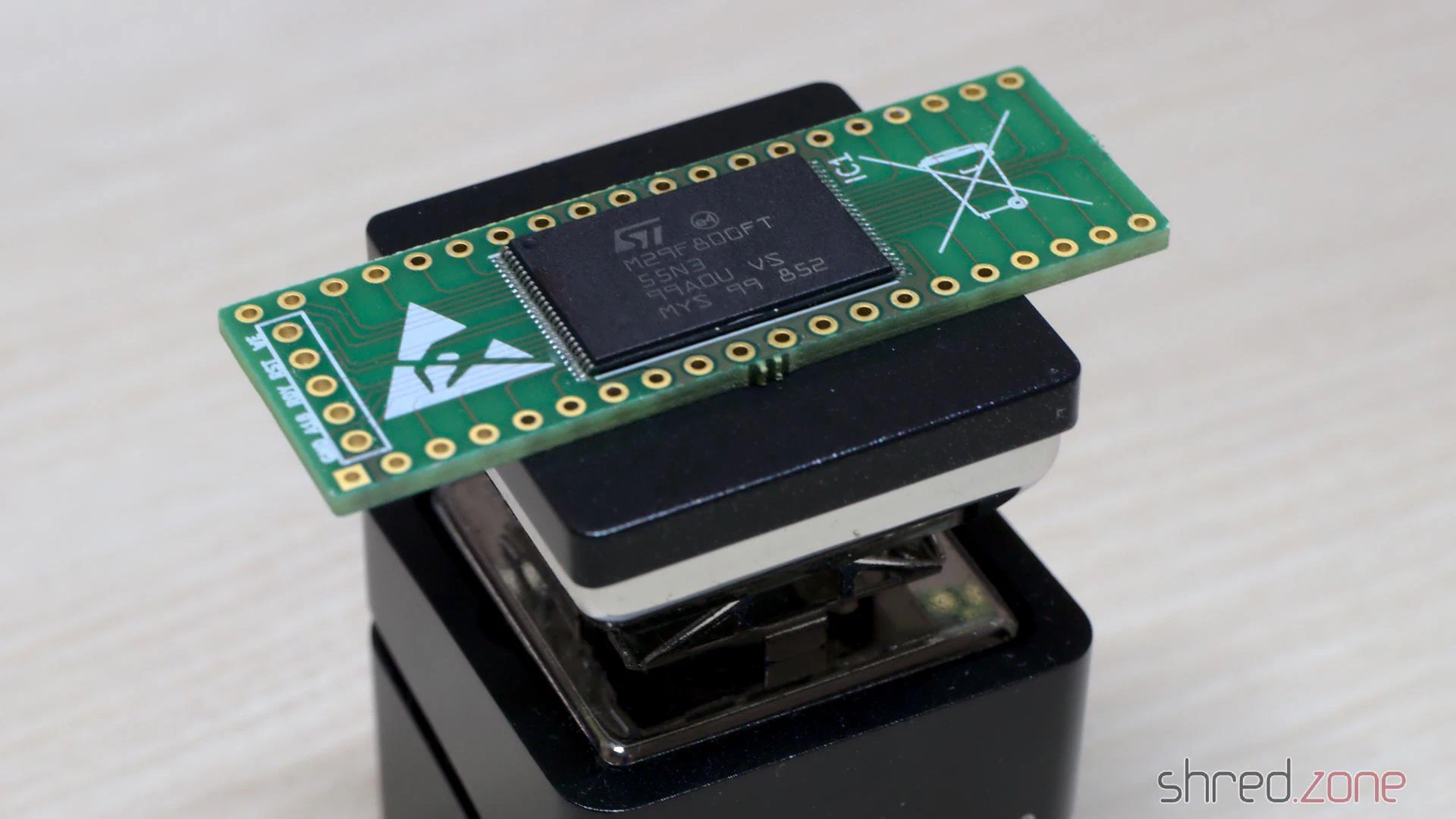 djbase kindly published the design of an Amiga Flash ROM Adapter. It can be equipped with 29F400, 29F800, or 29F160 Flash ROMs. They are available at all kind of electronic sellers, and can store up to four Amiga ROMs in a single chip.
Besides the PCB and the Flash ROM chip, you only need four SMD resistors, one SMD capacitor, and pin headers. The problem, however, is that the components are tiny, and the pitch of the Flash ROM chip pins is very fine, so this project is definitely not suited for soldering novices. Trust me. I made three of them for the bin before I was successful.
The Programming Hardware
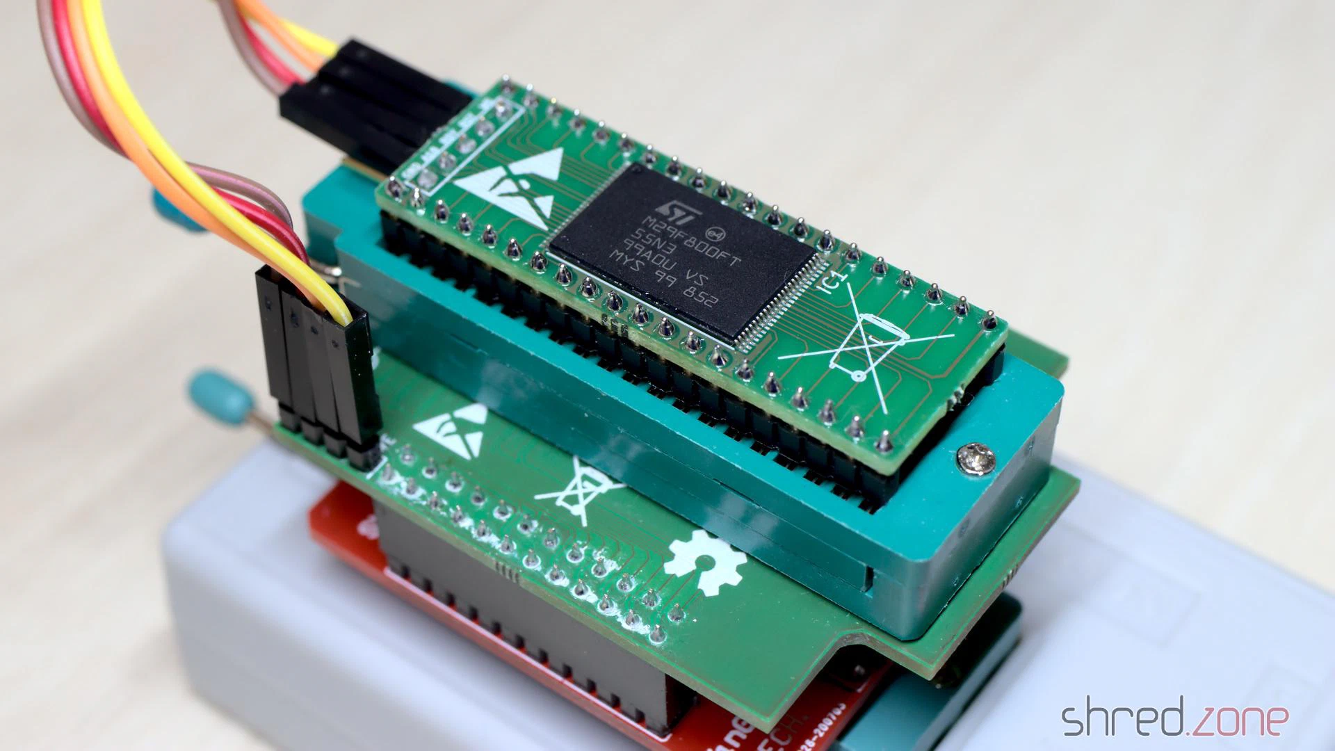 For programming, I use an XGecu TL866II Plus programmer and the SN001 Adapter Kit. djbase also provides a special programming adapter, which is connected to the TSOP48/SOP44 base board of the SN001 adapter kit.
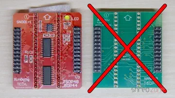
Note that you will need the active base board (SN001, red in the photo). The standard TSOP48 base board (green) won’t work here.
This programming adapter sandwich is put into the ZIF socket of the TL866 programmer. The Flash ROM adapter is placed into the ZIF socket of the adapter board, and the pin headers of both boards are connected according to their labels. Note that the current revision of the adapters support Flash ROMs up to the 29F160, and require five wires. I still use the previous revision with only four wires, because I like it better.
The GND pin of your flash board can be left open for the flashing process. It is typically used to connect a jumper or switch inside your Amiga, to select the ROM bank.
If you don’t intend to change the Flash ROM content after soldering, you can also save the programming adapter and use the SN003 adapter instead (which often comes bundled with the SN001 adapter kit). You would then flash the Flash ROM before soldering.
The Binary File
For preparing the binary file, I use my Pynaroma toolkit. It takes care for joining multiple ROM files and the necessary byte swapping. For example, to create a ROM image of AmigaOS 2.04 and AmigaOS 3.2.1 for the Amiga 500, this command line can be used:
rom2bin -o flash.bin A500.37.175.rom CDTVA500A600A2000.47.102.rom
Depending on the flash ROM chip, you can use up to four different ROM files of 512KB each. If the ROM file has a size of 256KB, remember to duplicate it.
Once the adapter is in the Amiga, the desired ROM image can be selected via the header address lines (e.g. by using jumpers or switches). Note that the address pins of the Flash ROM are pulled-up by the adapter. This means that the last ROM file of the sequence is used when all header pins are open.
Flashing
For programming, I prefer to use the open-source minipro software over the original software by XGecu, mainly because the original software is not available for Linux.
It is important to select the correct Flash ROM type. Pick the type that you have actually soldered to your adapter. Always choose the TSOP48 package, as the programming adapter simulates a TSOP48 socket.
I use a M29F800FT, so the correct device setting is M29F800FT@TSOP48, and the command line for flashing the binary file from above is:
minipro --device 'M29F800FT@TSOP48' --write flash.bin
The Flash ROM will be erased (so there is no need to erase it before), the image written to it, and then verified in a final step.
ROM Replacement
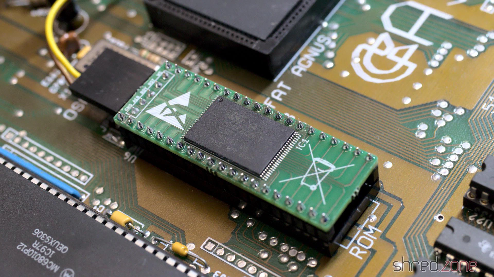 The Flash ROM is a drop-in replacement for the Amiga ROM. I carefully removed the original ROM from the socket by using a screwdriver with a wide blade.
After that, I put the Flash ROM adapter into the socket. The correct orientation is crucial. The adapter is put with the header having the same orientation as the notch of the original ROM.
Sometimes the holes of the socket are too small to receive the pins of the adapter. In this case the only chance is to either replace the socket, or use an EPROM.
If you own an Amiga 500 Rev. 5 mainboard and experience random crashes with the new Flash ROM, you might need to add resistors to the address lines. This can be done either via resistor packs or by using an Amiga 500 EPROM adapter that is sold at some Amiga shops.
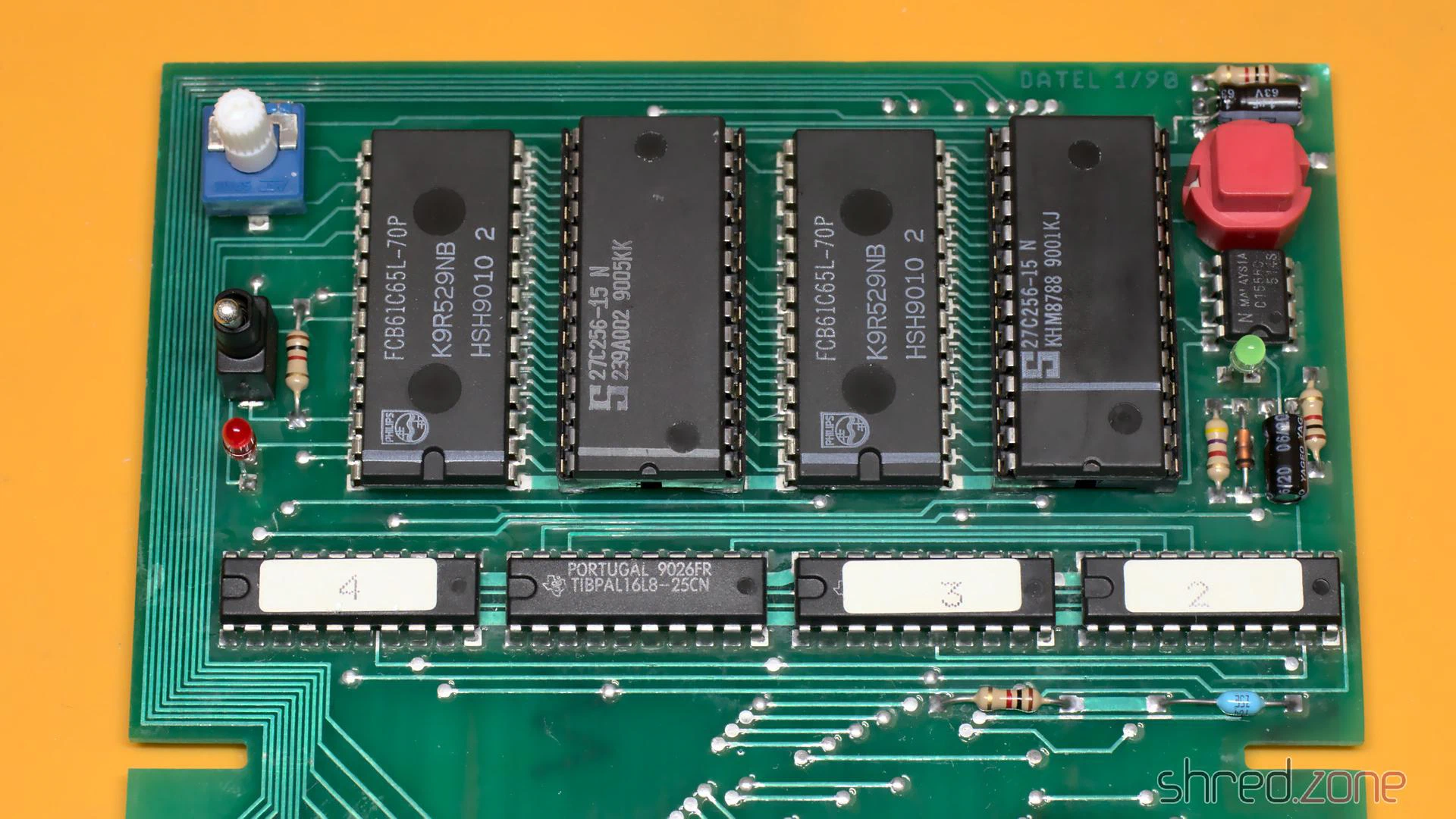
I got this Action Replay MK-I module. According to the seller it was untested, and for that reason sold as defective. It was in a… let’s say very used state. The case was dirty, to a point that it was almost revolting to touch it. A side of the case was cracked open, and a knob was missing. The module must have been dropped at some time.
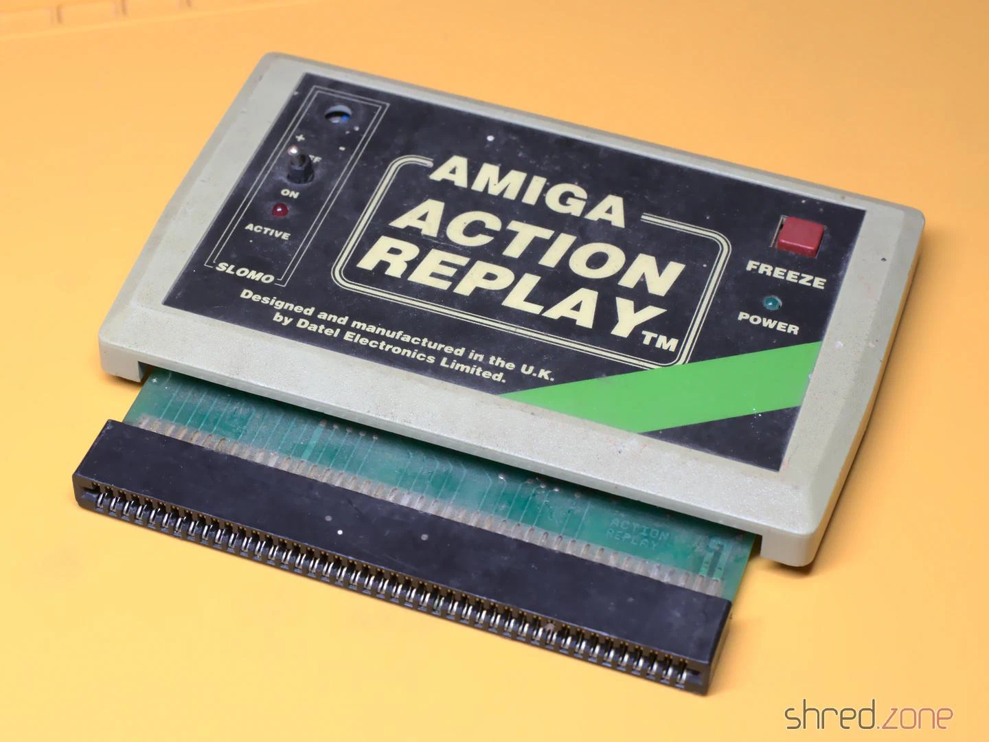
I carefully opened the case. The top and bottom shells are just stuck together, there are no screws, so it was easy to pull them apart. Inside I found some kind of coating on the PCB, so perhaps a drink had been spilled on the module as well. I also found a lot of fine paper dust like from a cardboard, and a small dent at the corner of the PCB that was caused by the drop.
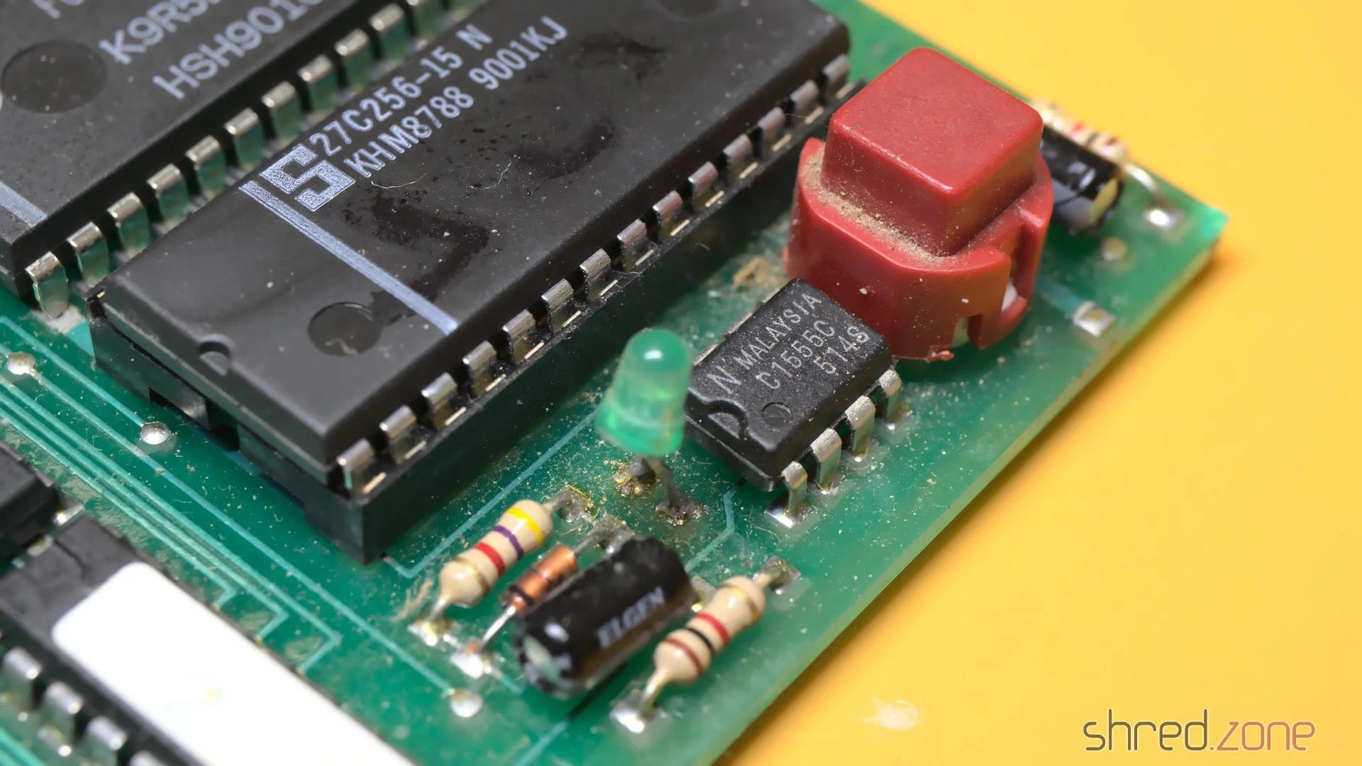
The first thing I did was to give the entire module a proper cleaning in an ultrasonic cleaner, just with warm water and a drop of dishwasher detergent. And yes, I also washed the PCB that way, then dried it off and sprayed it with IPA to remove the last traces of water. That bath did wonders.
I expected that the dirt also reached the inside of the mechanical parts, so I decided to replace them all. They were a bit hard to find as replacement parts, but still available. As the original knob was lost, I used a different potentiometer that came with a knob. Unfortunately the new one is white, while the original one has likely been black, so I couldn’t fully restore the original outside look.
The case was cracked open at one side because two pins inside were broken off. I fixed the pins with superglue. After that I exposed the case to the sun for a day, which removed quite a bit of the yellowing. Then I could put everything together again. Compared to the original state, the Action Replay is now looking nice and clean.
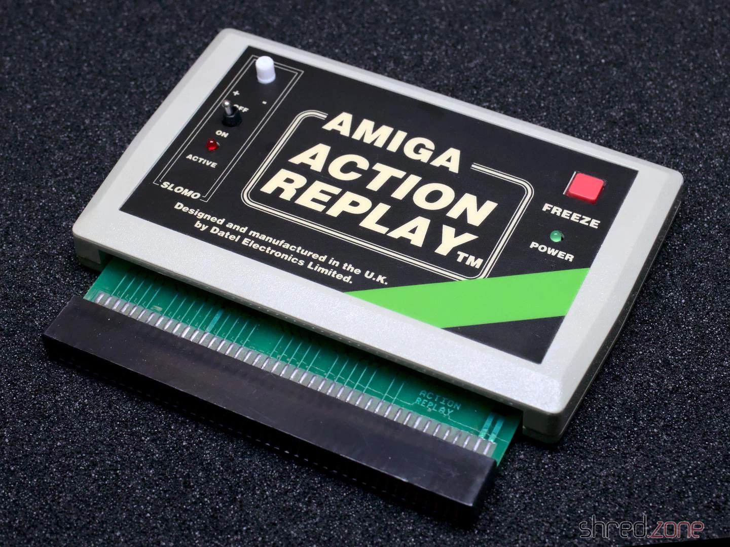
I gave it a test run in my Amiga 500, and it was working fine! Now I have an Action Replay for my Amiga collection. The only sad thing is that it cannot be upgraded to an MK-II or MK-III, as these modules are constructed differently.
AmigaOS was an operating system that was way ahead of its time. It had features that other home operating systems (like Windows or MacOS) were missing back then, like preemptive multitasking. There was also a feature that was called assignments. I truly miss that one on Linux!
An Amiga “assign” is a bit similar to the drive letter you may know from Windows. For example, the Windows path C:\example.txt refers to a file called example.txt in the root directory of the main partition, while the same file on the first floppy drive is called A:\example.txt.
On Amiga, the main partition is usually called DH0:, the second partition is called DH1: and so on, while the first floppy drive is called DF0:. A similar path on the Amiga would thus be DH0:example.txt or DF0:example.txt.
As you can see, on the Amiga a “drive letter” can actually consist of multiple characters and also numbers. This is called an assignment. The name DH0 is assigned to the main harddisk partition.
But wait, there is more!
You can have multiple assigns pointing to the same target. For example, the main partition usually contains the Amiga desktop environment, called Workbench. For this reason, the main partition also has a label like Workbench, and the file could also be accessed as Workbench:example.txt.
This is actually quite a smart concept, especially for exchangeable media. For example, let’s imagine we have just started a game called shredzone, and it needs to access a file Music/Opening.mod on its installation disk (AmigaOS uses a slash as file separator, like all proper operating systems). It would open a file called shredzone:Music/Opening.mod.
AmigaOS would see that there is no assignment called shredzone, and would pop up a dialog like this:
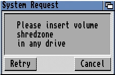
From a user’s perspective, I would now know that I have to find a medium called shredzone, and insert it into the computer. It does not matter if it’s a floppy disk, a CD, or even a network mount. AmigaOS also does not command me to insert the medium into a certain drive. If it’s a floppy disk, and I have multiple floppy drives, I can just pick the one I like to. AmigaOS will then detect that a medium with that name was inserted, would close the dialog, and grant the game access to the file.
On Linux, I would need to access that medium under a path like /run/media/shred/shredzone, which is a lot to type, contains my user name, and is harder to remember than just shredzone:.
But wait, there is still more! 😄
It is easy to add assignments to the system via command line. It’s even possible to use subdirectories as assignment target. Let’s stay with our shredzone game example. I got tired of having to insert the installation disk every time I want to play that game. So I create a directory called DH2:Games/Shredzone/Files on my hard drive, and I copy all files of that disk to that directory.
After that, I enter this command on the command line:
assign shredzone: DH2:Games/Shredzone/Files
Now, when I start the game, AmigaOS will see that there is a shredzone assign already existing, and will access the files there. So the song file shredzone:Music/Opening.mod would be accessed at DH2:Games/Shredzone/Files/Music/Opening.mod.
AmigaOS makes use of assigns itself. For example, there is a standard assignment called C:. It usually points to the C directory of the booting device, where all command line commands (like dir, copy, delete etc) are expected to be present. This assign is similar to what $PATH is to a Linux shell.
Imagine I have installed a set of development tools, like an assembler and a C compiler. The commands of this toolset can be found at DH1:Development/DevTools/C. On a Linux system, I would add this path to the $PATH env variable, so I can just type the command name to execute one of these commands.
On AmigaOS, I just add this path to an existing assignment:
assign add C: DH1:Development/DevTools/C
Now AmigaOS knows that when I enter a command in the command line, it has to look for it in Workbench:C, and if it’s not found there, it will try to find it in DH1:Development/DevTools/C. I could even execute commands like dir C:, and see all files in both directories. Of course, it is not limited to two targets.
There is still more, like deferred assigns. But I only want to give you a general impression of what Amiga assigns are, and why I miss them on Linux.