When I saw this Amiga 1200, I immediately felt sorry for it. The case and the keyboard were already heavily yellowed, but even worse was the botched attempt to fit a Gotek drive into the case. To make room for it, the previous owner obviously broke open the area around the floppy drive with pliers or wire cutters, completely ruining the beautiful old case.
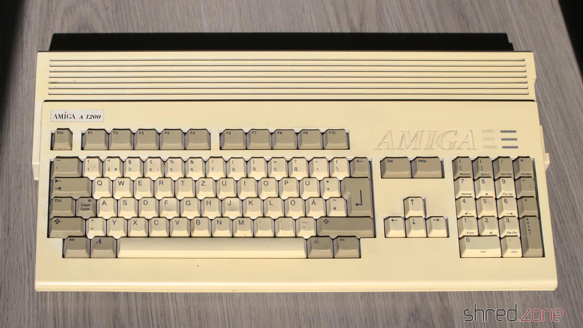
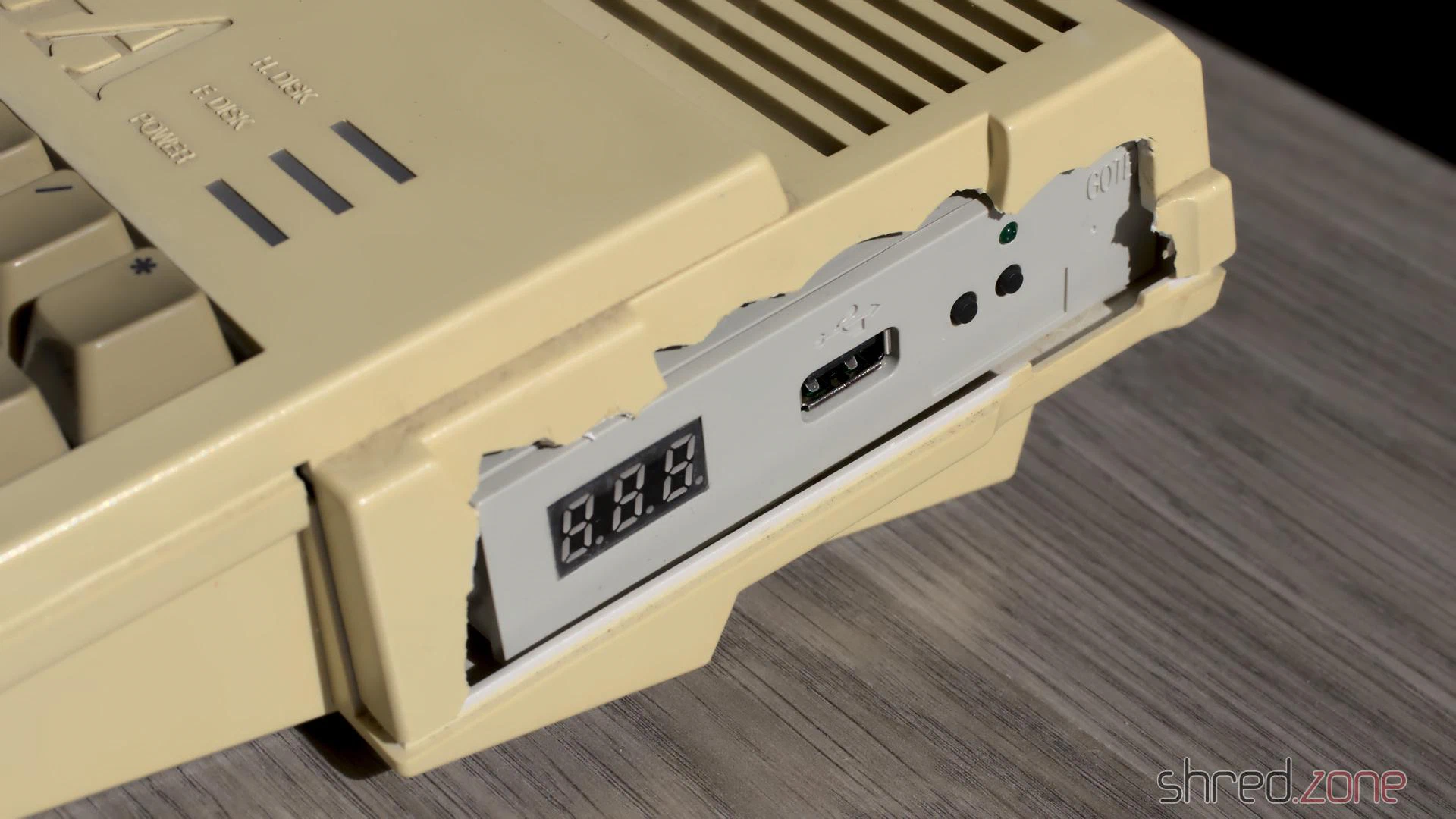
Originally, I had planned to bleach the case and the keyboard. I wanted to tidy up the ugly opening at the floppy drive with a rotary tool and then close it with a 3D-printed part as best as possible.
But then I had a much better idea. 😁
The motherboard
First, let’s take a look inside. A Rev 1D.4 board in good visual condition is installed. I replaced the electrolytic capacitors and updated to AmigaOS 3.2.1.
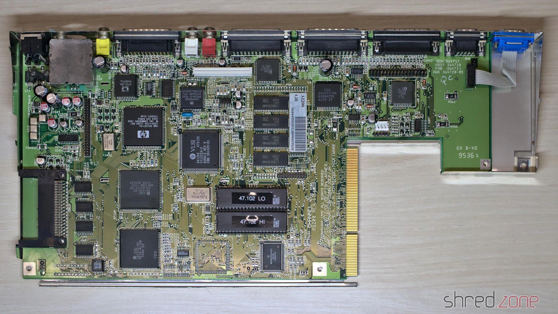
On the underside of the board, I found a copper wire for a so-called “floppy fix”. When Escom produced the last Amiga 1200s, there were no Amiga floppy drives left. Instead, they installed standard PC floppy drives. However, many games and demos didn’t run on the machines modified in this way.
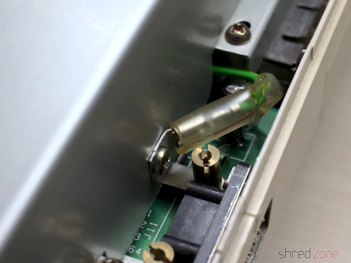
The original floppy drive of this computer was no longer present, and Gotek drives can perfectly emulate Amiga floppy drives. So I decided to reverse the floppy fix. To do this, the jumper wire is first removed. To restore the original RDY signal, a wire is then soldered from pin 34 of the internal drive connector to pin 1 of the external floppy port.
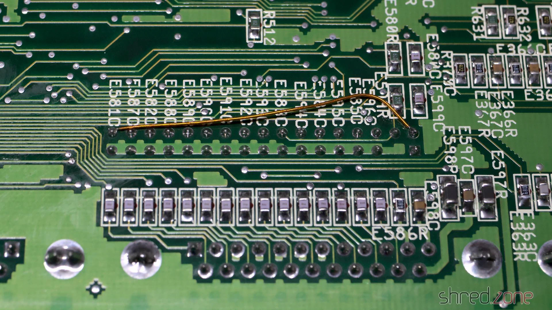
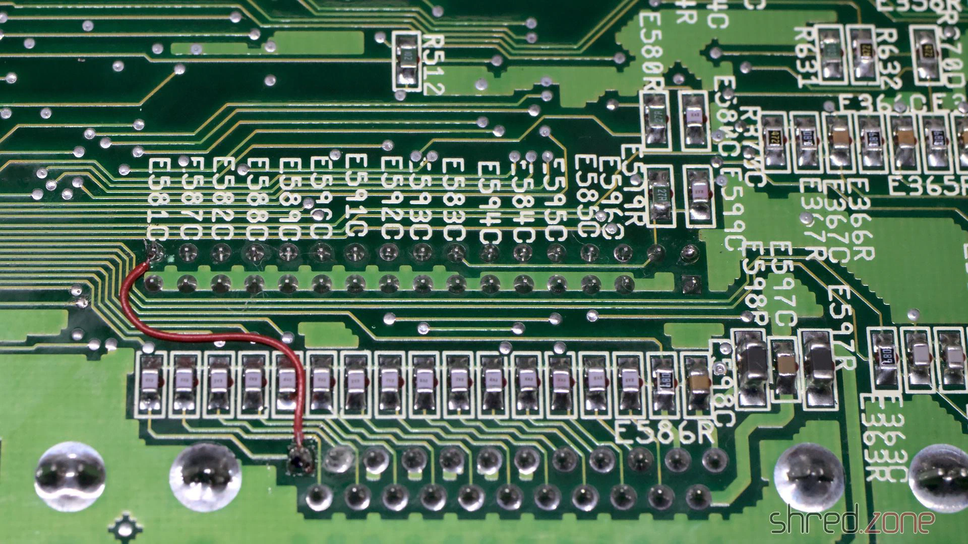
Since I was working on the underside of the board anyway, I also wanted to remove E123C and E125C to improve the stability of accelerator cards. However, the capacitors hadn’t even been populated in the first place, so that was sorted.
That meant it was time for a first thorough test run. Everything went well so far, until I noticed that the right mouse button didn’t work on either port. A separate blog article describes the cause and the fix. In short: you have to replace four resistors with ferrites.
My work on the board was finished after that. It now passed all diagnostic tests.
The extras
As with my other restorations, I don’t just overhaul the machine, but also future-proof it with a few extras.
First up: the yellowed case with the ugly cut. It was clear to me that the case would never look truly nice again, even with a half-decent restoration attempt. Besides, I had always wanted a black Amiga. Therefore, I treated the Amiga to a brand new, black a1200.net replica case instead.
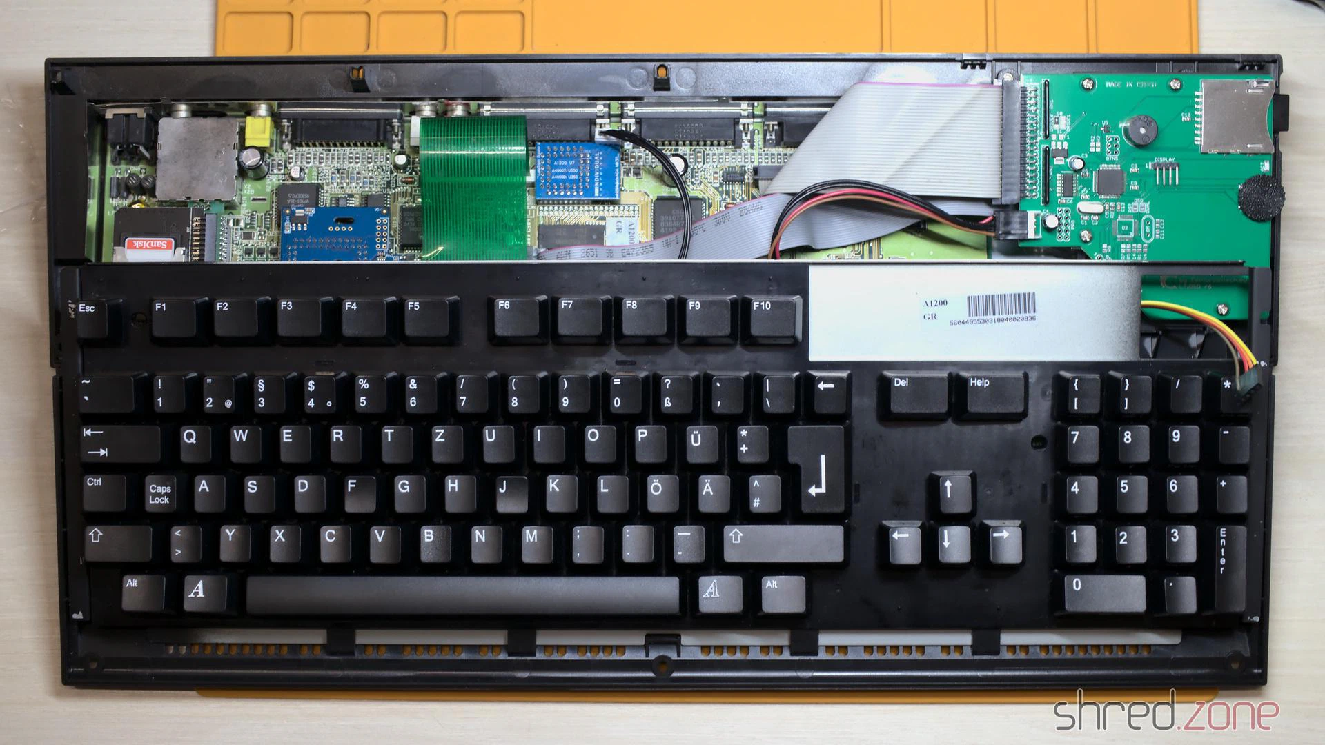
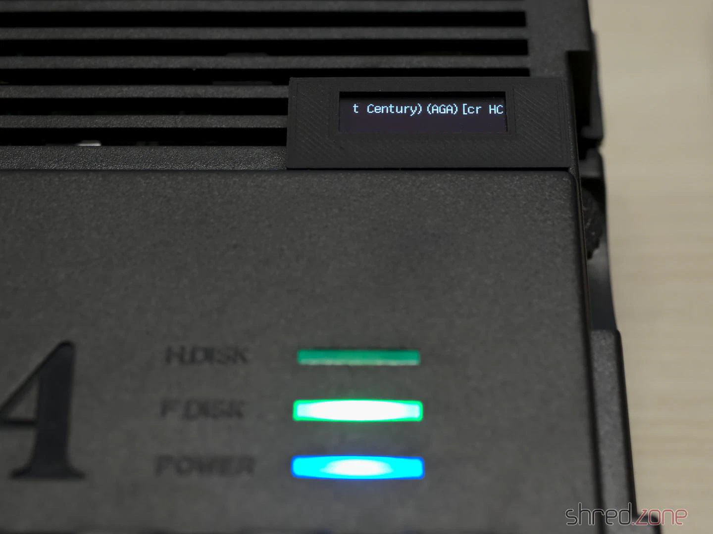
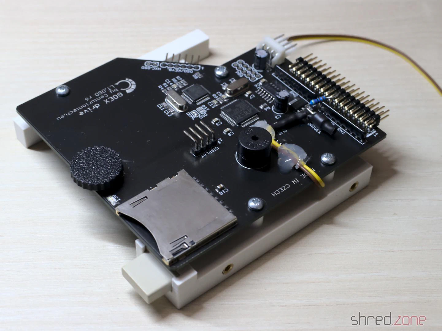
The floppy drive was missing. Instead of the Gotek drive that was originally supposed to take its place, I chose a Centuriontech GoEX drive. Instead of a USB stick, it uses an SD card. It also features a rotary switch that makes selecting the floppy image easier. Matching OLED displays are available as accessories, but for my new Amiga, I wanted a much smaller display that wasn’t as conspicuous.
I used a 0.91" OLED display, the kind you can find in practically any maker shop. Here it is important to swap pins 1 and 2 when soldering the cable, as the power pins on this type of display are swapped compared to the original GoEX display module.
I printed an A600 display module case, which fortunately also fits an A1200. I joined the individual parts together with hot glue. In hindsight, I should have used normal glue, as the hot glue softened the PLA of the print a little. The cable is then routed through the cooling vents of the Amiga and the module is clipped on, gluing is not required.
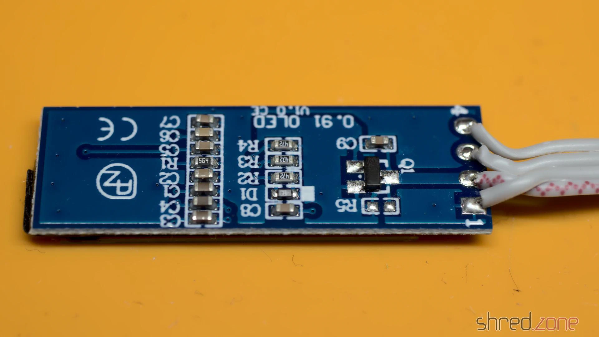
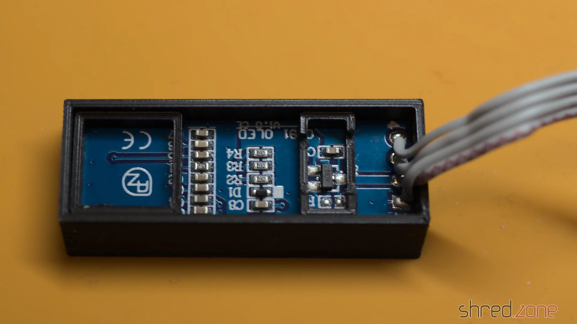
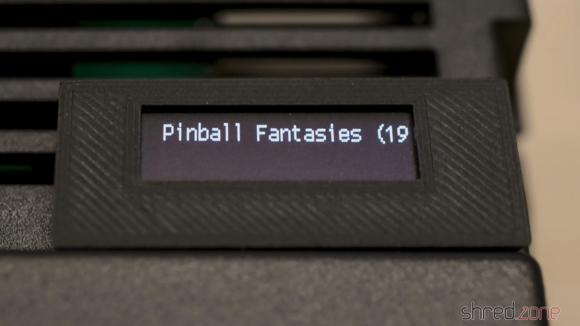
For the GoEX to use this OLED size correctly, a file named FF/FF.CFG must be created on the SD card with the following line:
display-type = oled-128x32
For a pixel-perfect image via HDMI, I also installed an Indivision AGA MK3. It turned out that the a1200.net replica case seems to have slightly different dimensions than the original case. I therefore designed a modified trapdoor and bracket for this case type.
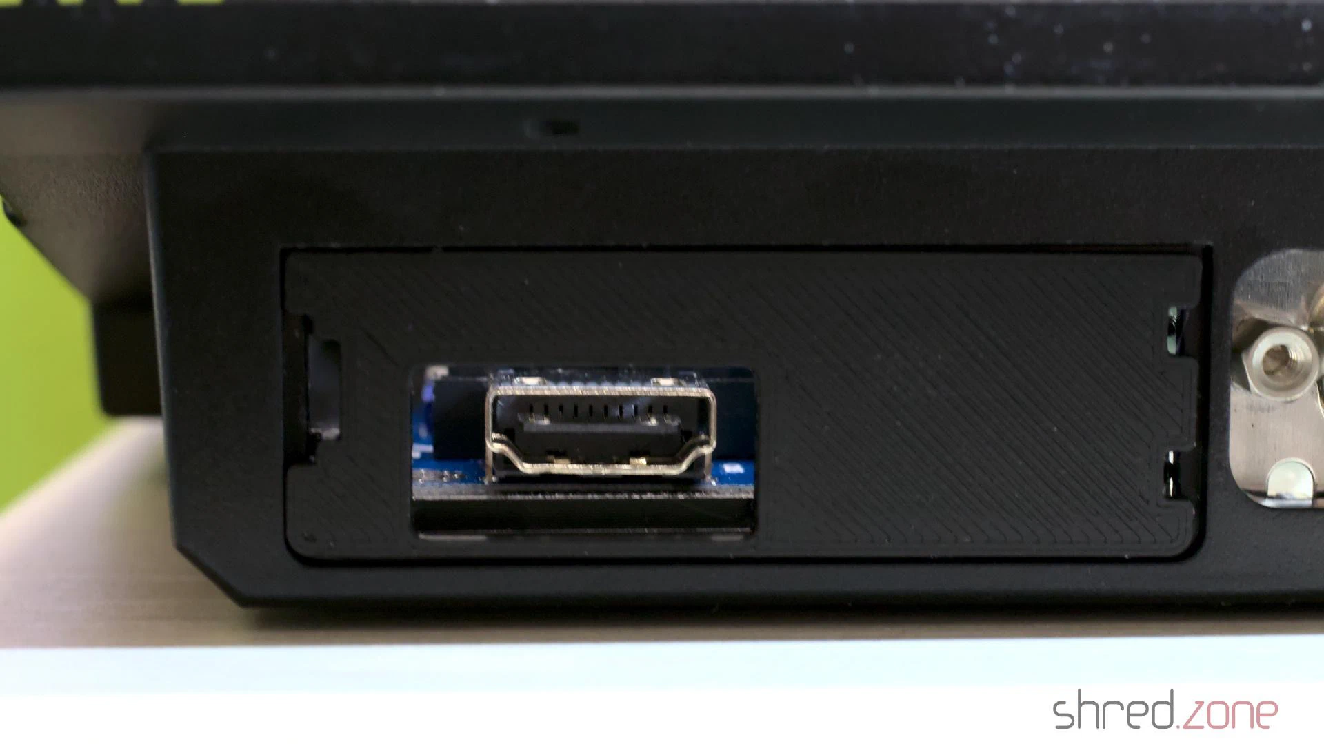
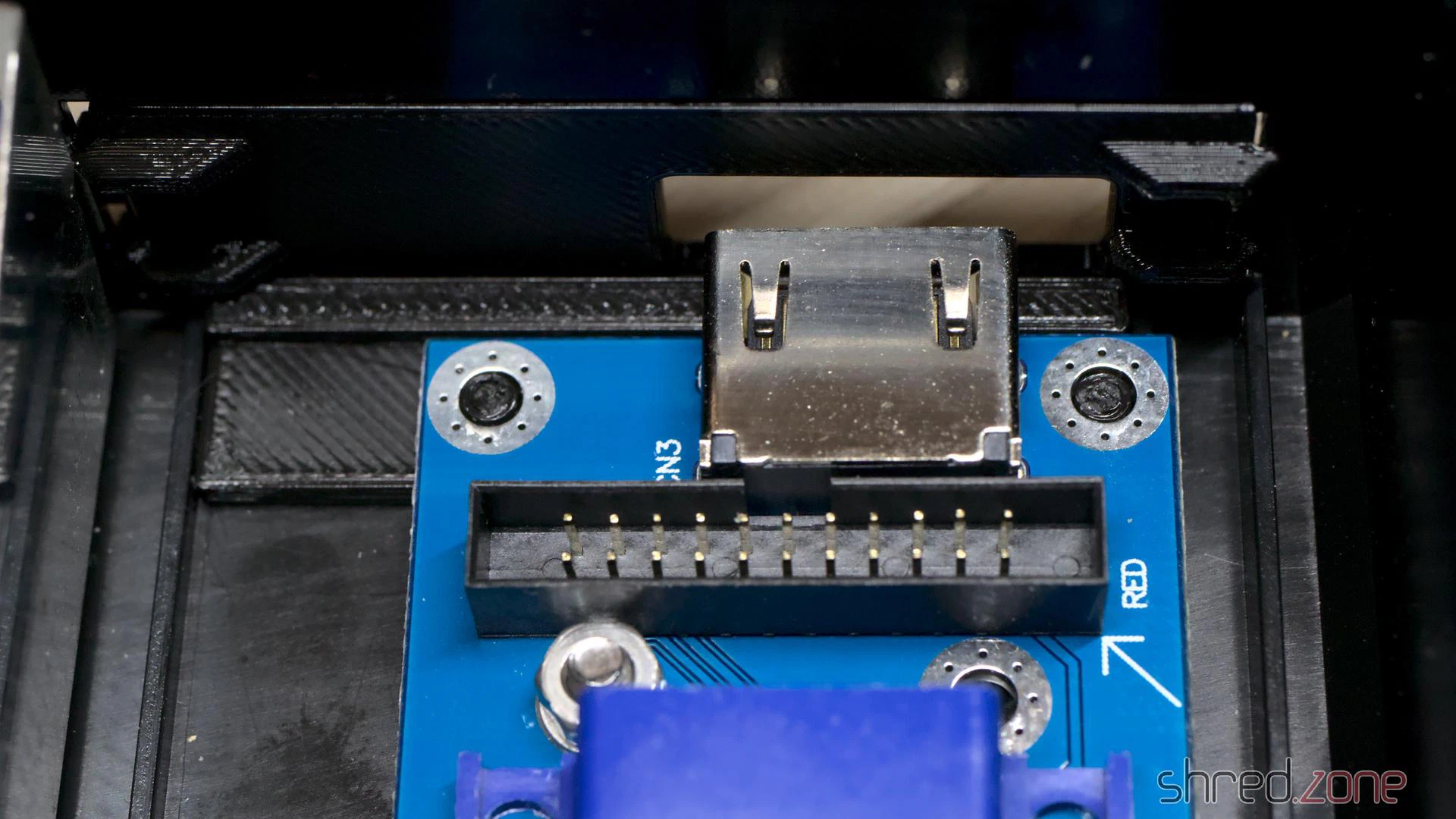
When I got the Amiga, there was already a Marpet Developments M1207 RAM expansion in the expansion slot. It was treated to a fresh coin cell battery and now provides the machine with an additional 4 MB of Fast RAM, a 68882 FPU and a real-time clock.
And last but not least, the machine got custom LEDs, with the power LED in my signature colour, blue.
Assembly
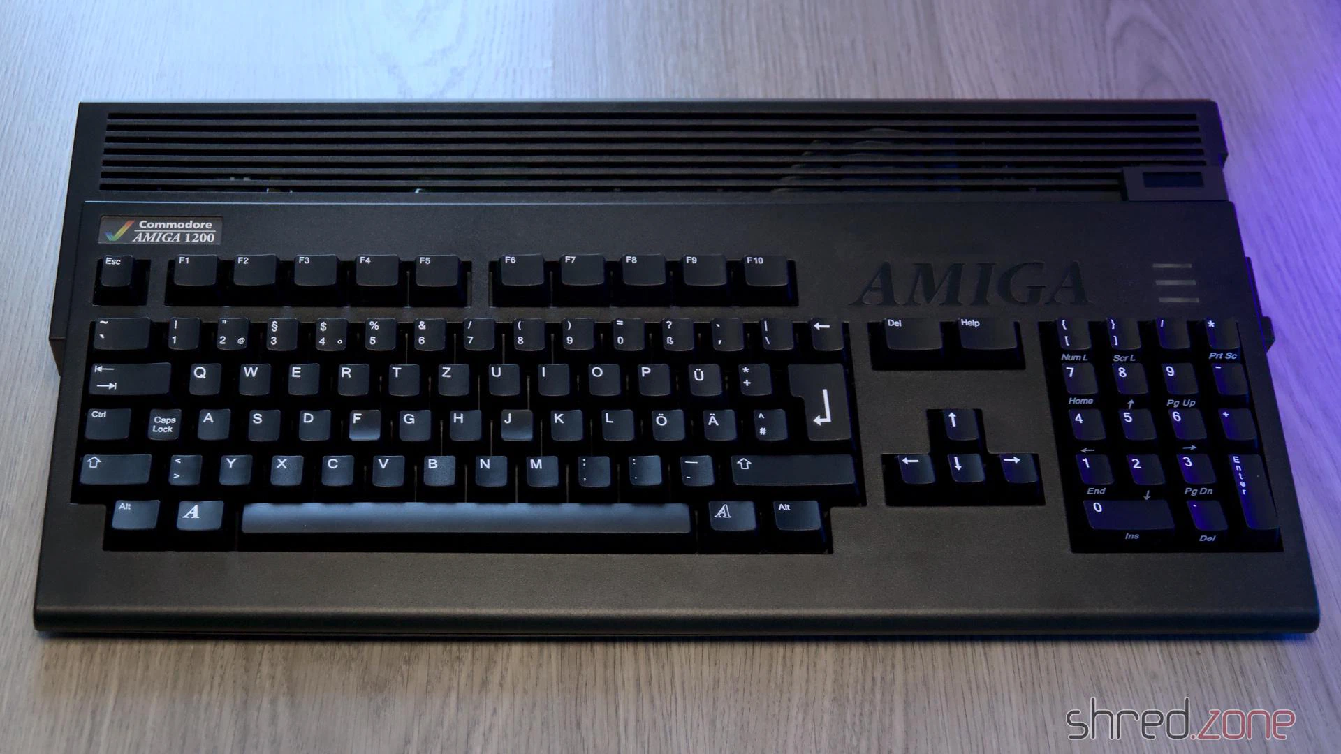
What’s still missing? The black keycaps, of course, to match the black case. After many years of waiting, they were finally available, and I had a set delivered just in time for Christmas.
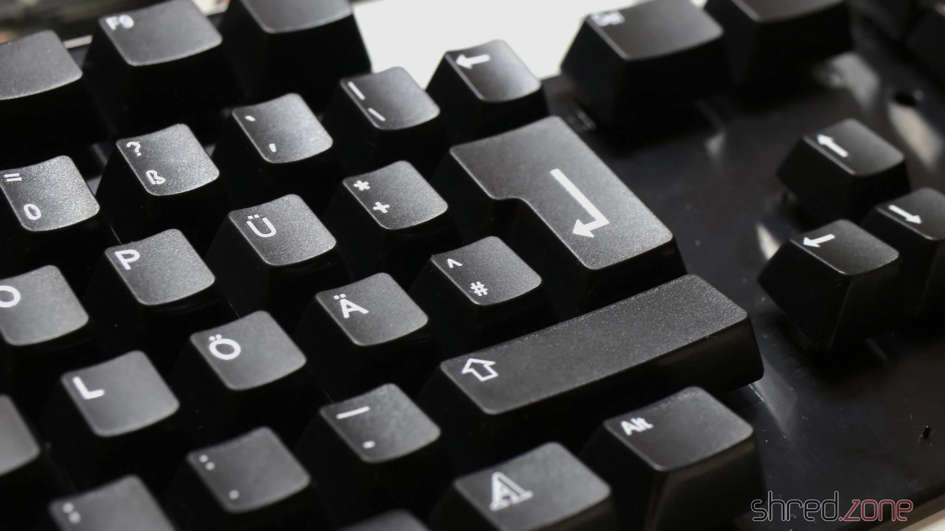
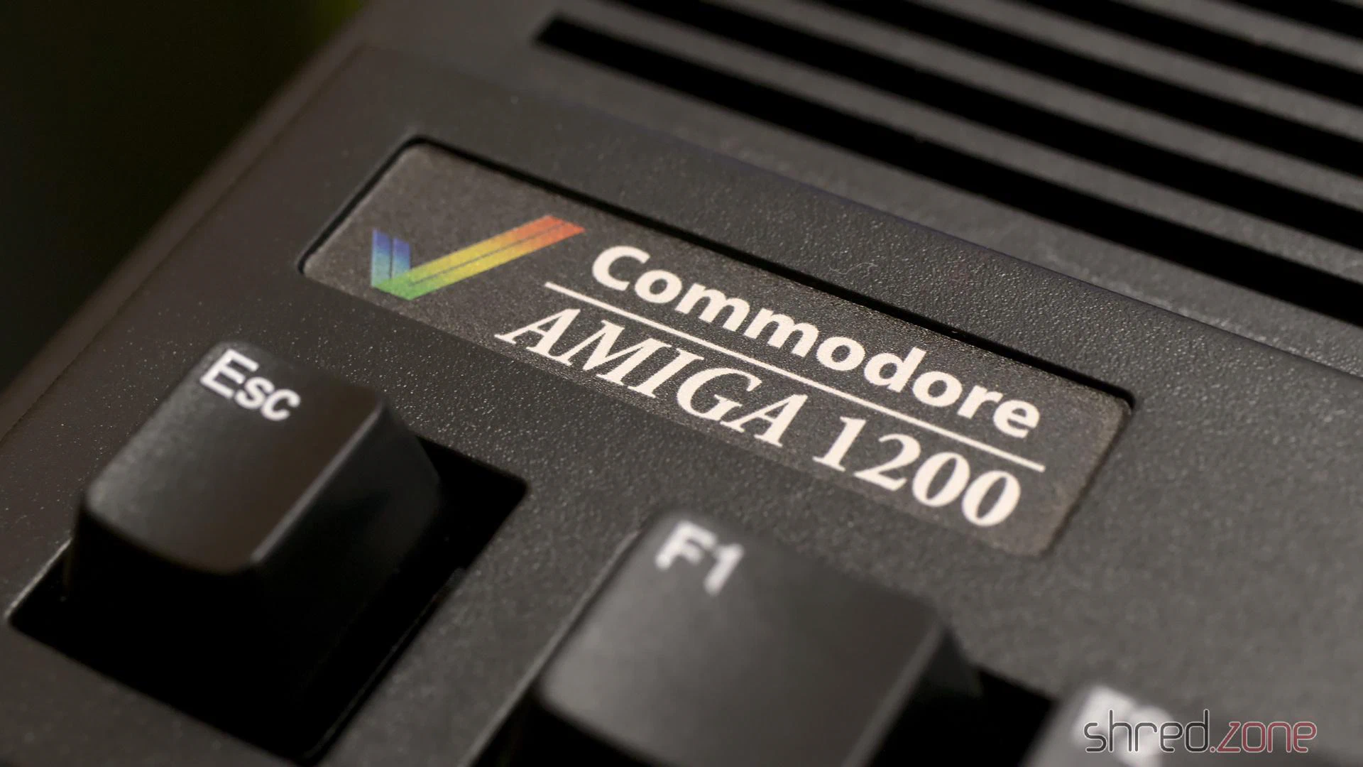
Unfortunately, a matching badge is not included with the black case, but Badgeman had something suitable in stock.
After that, the Amiga was ready for final assembly.
If Commodore had given us a choice of case colour back in the 1990s, I would have chosen a black Amiga. And now here it is, a completely black Amiga 1200 with a totally new exterior and a modernised interior.
Debug.lib, which is also used by all kind of tools like MuForce, Mungwall, or PatchWork. AmigaOS provides a simple internal debugger called ROMWack (which has been replaced by the even simpler SAD in later versions). But also DiagROM is writing diagnostics data via the serial port, which comes in handy when a RAM chip or something in the video area is broken.The log output is sent to the serial port and can be read by a terminal connected to it. Back in the good old days, not so many hobbyists could afford an actual terminal or a second computer for that, so we used tools like Sushi or Sashimi to redirect the debug output into a Shell window, which worked fine unless the system has crashed too hard.
Today, I assume that almost all of the Amiga owners also have a second computer at home, and if it’s just a second Amiga. 😉 This blog article is about how to connect your Amiga to your Linux PC, and get the debug output.
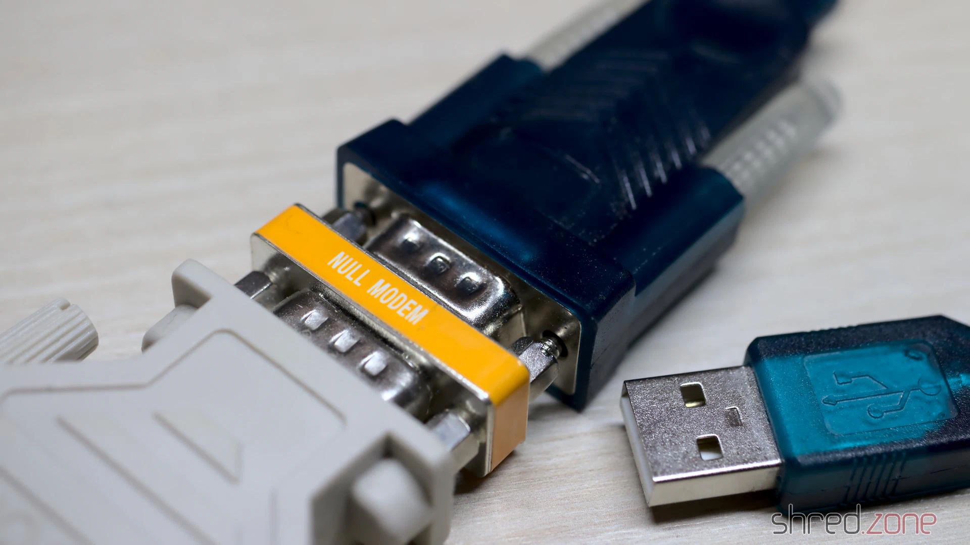
On the hardware side, you will need a construction with a DB25 female port on the one end, and an USB connector on the other end. I use one of those USB-to-Serial converters that can be found on hardware shops for little money. They are often equipped with a DB9 male connector, and are supposed to be connected to peripheral devices (like modems). To connect them to a computer, a so-called zero modem (or null modem) is required, which is just a small adapter that enables to connect two computers directly together by crossing the transmit and receive lines. Finally, we need a DB9-to-DB25 connector with the correct genders, to connect the other end of the zero modem to the Amiga.
This hardware stack is connected to the Amiga’s serial port on the one end, and to a USB port of the PC on the other end. Remember to turn off the Amiga before connecting something to the serial port. Unlike USB, the ports of old computers are not designed for connecting or disconnecting devices while the system is powered. It could actually damage the system to do so!
On the software side, we don’t need to install drivers on the Amiga. The debug or diagnostics output is just sent to the serial port. On Linux, we can use any terminal emulator. The most prominent is certainly minicom.
The default serial port settings are 9600-8N1 (9,600 bps, 8 bits per character, no parity, 1 stop bit). However, the debug output is just directly sent to the serial port. If you changed the serial parameters on Amiga side, and used the serial.device for something else, the debug output will use the current settings. Handshake must be turned off in any case, though.
Maybe the easiest way is to create a file called ~/.minirc.amiga with the following content (change the pu port value to your actual TTY USB device):
pu port             /dev/ttyUSB0
pu baudrate         9600
pu bits             8
pu parity           N
pu stopbits         1
pu rtscts           No
pu xonxoff          No
On many Linux distributions, the user also needs to be added to the dialout group in order to access a serial device:
sudo usermod -aG dialout $(whoami)
After that, just start minicom with the amiga profile:
minicom amiga
Now you should see all the debug output generated by AmigaOS on your minicom screen. For interactive debuggers like ROMWack, you can also type commands into the console.
To leave minicom, press CTRL-A and then Q. 😉
Amiga CD32
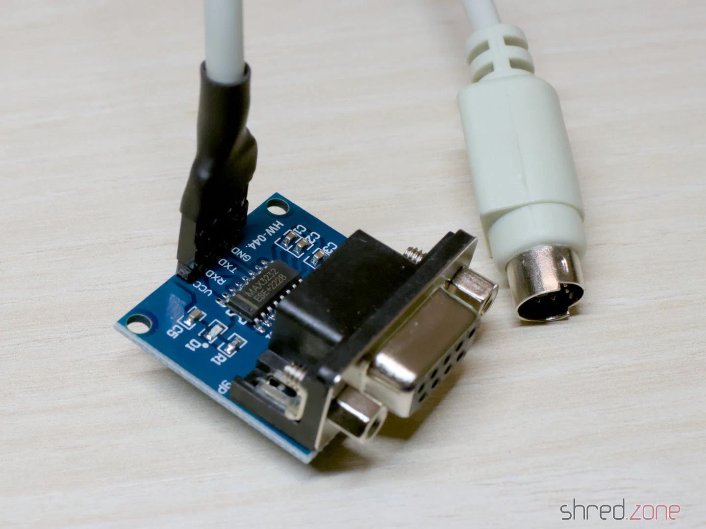
To build an adapter, you need a PS/2 cable (e.g. from an extension cord or an old PS/2 input device) and a MAX3232 based TTL-to-DB9 level converter. These converters can be found at online marketplaces for a few Euro.
Cut one end of the cable and connect the wires to the converter like that:
- Pin 2: TXD
- Pin 3 (and the shield): GND
- Pin 4: VCC
- Pin 6: RXD
Leave the remaining two wires unconnected, and check for correct polarity before connecting the wires to the converter!
The CD32 does not provide any control and handshake signals, but fortunately they are not needed for debugging and diagnostics purposes.
Whilst repairing an Amiga 1200, I noticed that the right and middle mouse buttons were unresponsive on both ports of this machine. It worked with an original Amiga mouse, but not with my YAMI mouse adapter. However, the mouse adapter couldn’t be the cause, as it has worked reliably for decades on all sorts of Amigas, including another Amiga 1200.
The problem is already known to the community and seems to affect other mouse interfaces as well. The solutions I could find so far were:
- Just use the original Amiga mouse. 😉 Despite all the love for old hardware: the era of ball mice is over.
- Modify the mouse adapter. For some, there is even a “fixed” version.
- Use a “FixRMB” tool. However, the tool has to be started first, so it doesn’t work in games or in the boot menu. It also requires a mouse adapter with internal pull-up resistors. YAMI doesn’t have these, for example.
- Swap the Paula. The soldering work requires experience and suitable equipment. Furthermore, it’s a shame about the otherwise fully functional Paula.
None of these options really appeal to me. I want this Amiga to work like all the others. So I went looking for the cause.
The middle and right mouse buttons are connected to the Paula’s POT pins. These inputs are actually intended for analogue joysticks and use a very simple ADC. The analogue joystick charges a capacitor whilst a counter in the Paula measures the time. The charging process takes varying amounts of time depending on the joystick’s position. Once a certain voltage level is reached, the counter is stopped. The counter value reflects the capacitor’s charging time and therefore the joystick’s position.
For mouse buttons, there is a digital mode. Here, a built-in pull-up resistor pulls the POT line to High. As soon as a mouse button is pressed, the line is pulled to Low. The result can be read directly from the Paula registers.
With an original mouse, there was 0.9 V on the POT line on this Amiga when the button was pressed. With the mouse adapter, it was a mere 1.1 V. This seems like only a minor difference, but on this Paula chip, it was already enough for “button pressed” and “button released”.
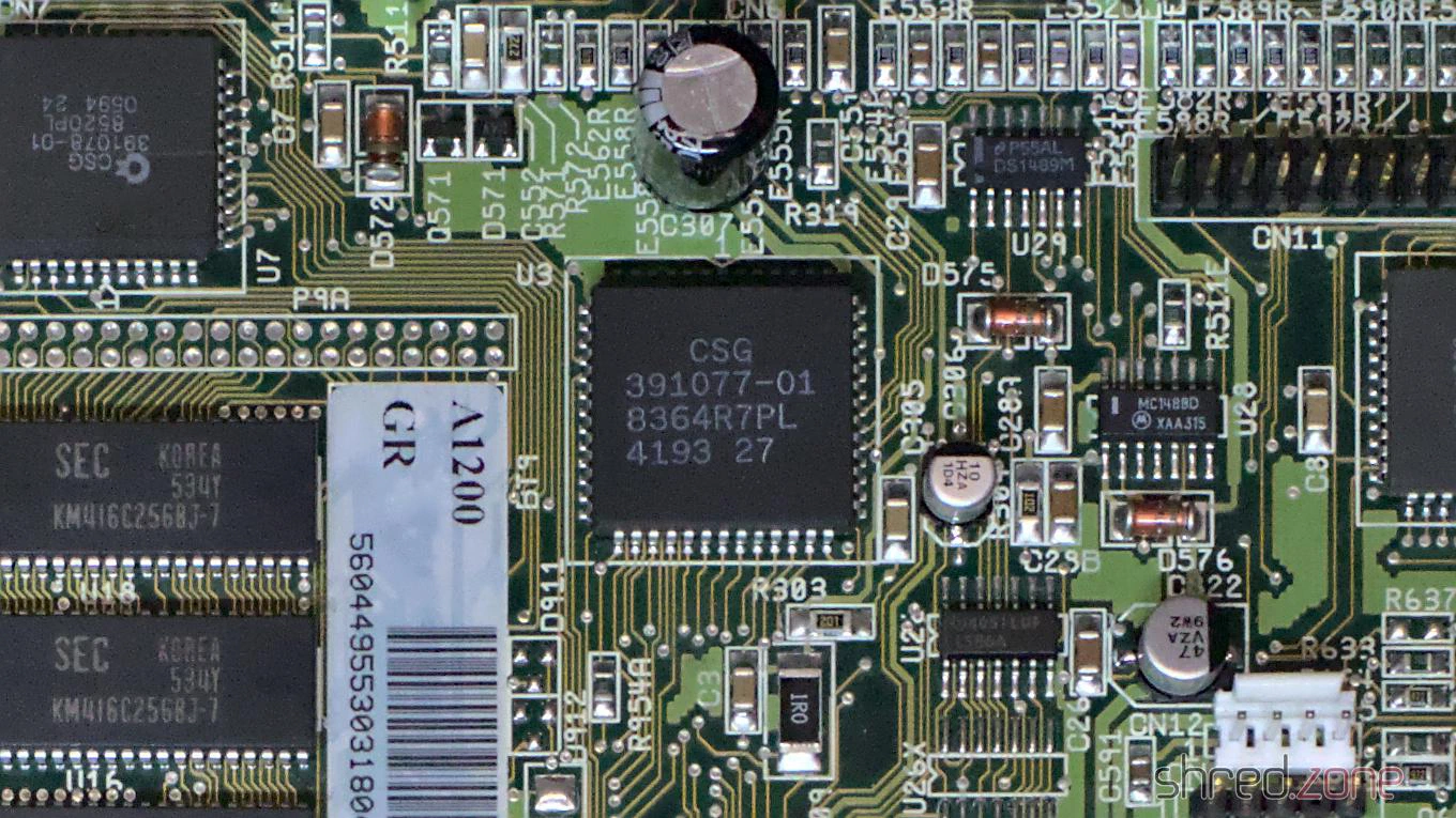
Now comes the exciting question: Why does the problem only seem to occur on Amiga 1200 models, even though the affected Paula batch was probably also used in Amiga 4000 production?
If you compare the schematics of both machines, there is a small but important difference. This is a simplified diagram of the joystick or mouse port for both models:
The essential difference lies in the components circled in red. In the Amiga 4000, Commodore installed EMI filters there. Basically, they are nothing more than a bare wire in a ferrite. They filter out high frequencies, but act like a 0 Ω resistor at low frequencies (like a mouse button).
In the Amiga 1200 and Amiga 600, Commodore installed 68 Ω resistors here, presumably to lower the production costs for the low-end models. (Interestingly, Commodore returned to ferrites on the CD³².)
What effect does this resistor have? Together with the pull-up resistor built into the Paula, it forms a voltage divider. The switch in a classic Amiga mouse pulls this divider to ground, resulting in 0.9 V at the POT input. This is just enough to be recognised as Low.
A mouse adapter, however, doesn’t have real switches, but logic outputs. The PIC16F84 used in the YAMI interface, for example, has a Low level of about 0.6 V. The voltage divider then delivers 1.1 V at the POT input, which is interpreted as High by this Paula batch. The mouse button is no longer recognised as being pressed.
I don’t know if the pull-up resistor has too low a value in this Paula batch or if the threshold for Low levels is lower. Both would be possible.
To fix the problem on my Amiga 1200, I replaced the 68 Ω resistors E353R, E354R, E363R and E364R with SMD 1206 ferrites, as used in the Amiga 4000. They are slightly larger than the 0804 resistors, but can still be soldered directly onto the pads.
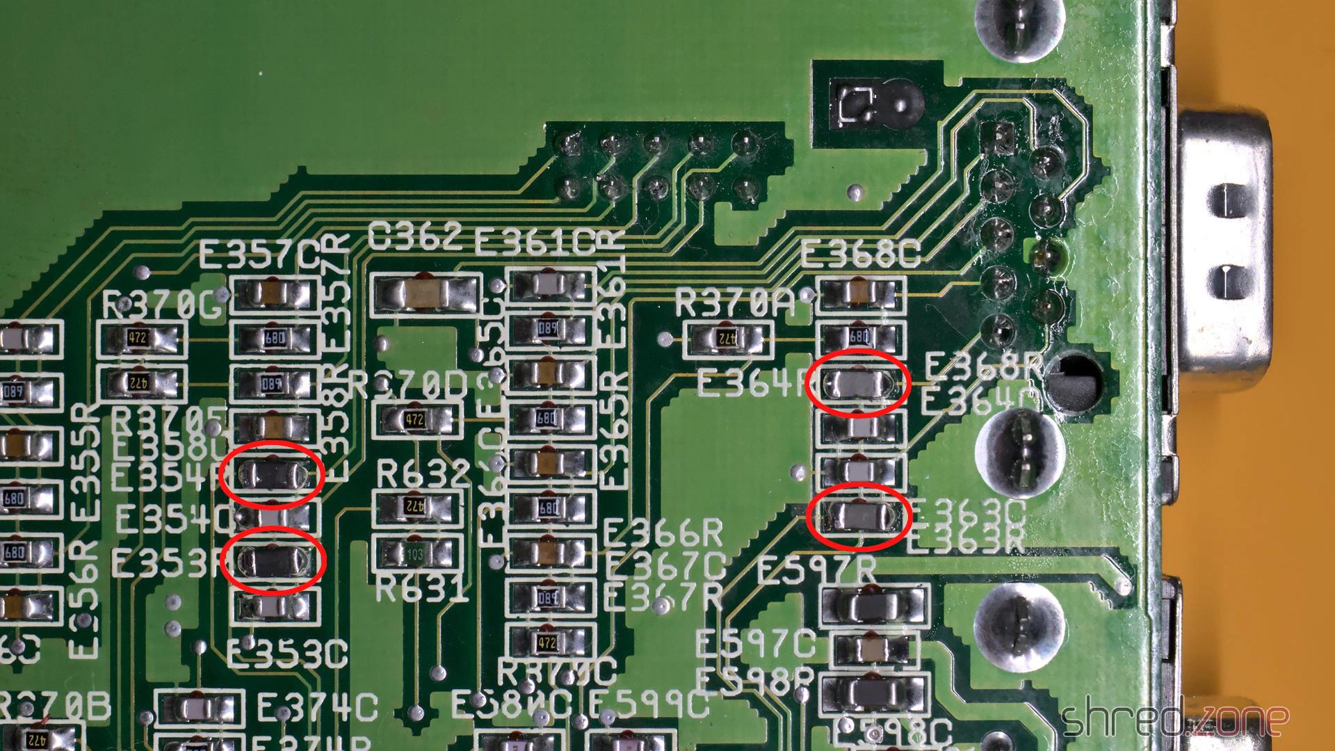
You also need to replace E353R, E354R, E363R and E364R when working on the Amiga 600.
This is just a minor hardware modification that can be carried out even with little soldering experience. Certainly more so than swapping a PLCC chip.
Following the change, the mouse adapter also worked reliably on this Amiga.
Make sure to replace the resistors with ferrites, not the capacitors next to them! The resistors are typically printed with the number 680. (Nothing would break if you accidentally swapped the capacitors, but the right and middle buttons would then be permanently pressed.)
PS: If you found this article because your Amiga has this problem too, please send me the date code of your Paula chip. Perhaps we can find a pattern of “bad” date codes. Thanks!
In the previous part, I refurbished the keyboard of the Amiga 1000. It was in a bad state, and truly deserved to get its own part. Now I will replace the floppy drive with a Centuriontech GOEX on pills floppy simulator, and then put everything back together.
Floppy LED
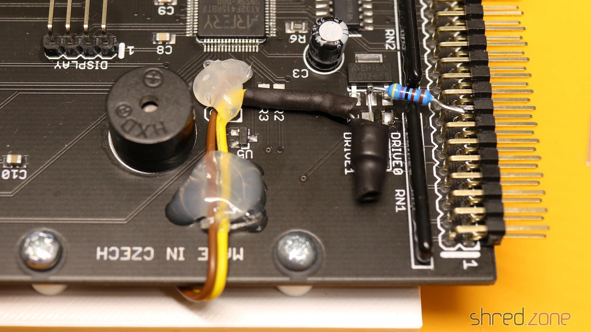
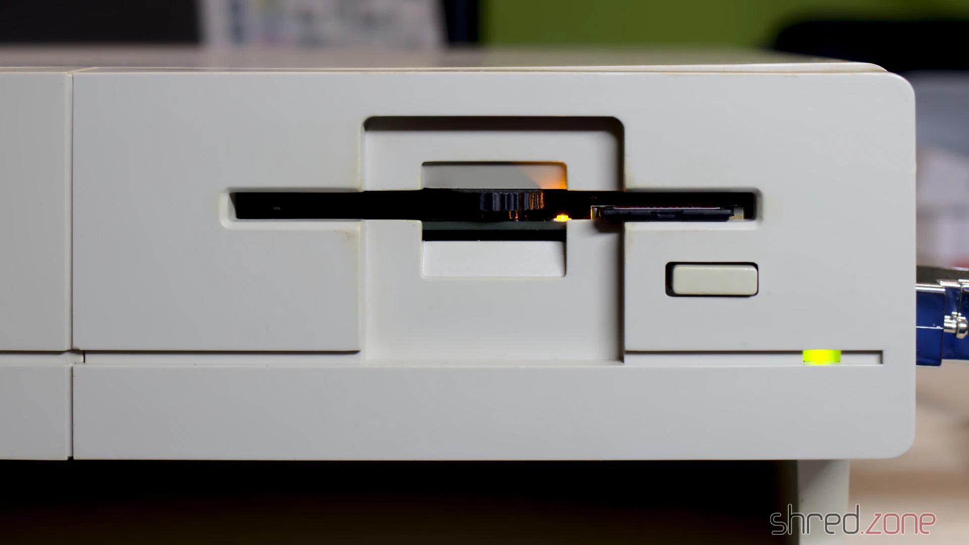
The floppy LED of the Amiga 1000 is not connected to the mainboard, but to the floppy drive. The GOEX drive does not provide a similar connector, so I had to come up with a solution. Fortunately, the Amiga made it faily easy.
On all Amiga models, the floppy LED represents the state of the drive motor. It lights up as long as the motor is powered. On the Amiga 1000, the motor of the internal drive is controlled by a MTR0LOW, the motor is powered, and the floppy LED is supposed to light up. The 7438 buffer inside the Amiga has a maximum output current of 48mA, while the LED has a forward current of 30mA, so in theory the LED (and a 120Ω series resistor) could be connected directly to the MTR0
I used a BC557, but any other standard switching PNP transistor will do as well. For the LED, I preferred to have a green floppy LED instead of the original red one. I used a Dialight 521-9266, which has the same dimensions as the original LED. There should be a pullup resistor on the MTR0
On the GOEX board, +5V can be found on an unused pad next to the voltage regulator. GND can be found at an unused header for an optional encoder.
On Screen Display
The GOEX drive needs some kind of display, to show the floppy disk file that is currently selected, and other options. My first plan was to glue a tiny OLED display to the front of the case.
However, the “GOEX on pills” model comes with an OSD connector. It reads the CSYNC signal from the Amiga, and generates a pixel signal that is overlaid to the Amiga RGB signal. Depending on the color component the pixel signal is connected to, the OSD text is either red, green, or blue (with the corresponding complementary color as background).
The CSYNC signal can be taken from pin 12 of U6A. The pixel signal is connected to one of the 75Ω resistors: R25 (red), R24 (green), or R23 (blue). The wire must be soldered to that end of the resistor that is closer to the monitor connector, otherwise the OSD overlay will not be visible on white screens.
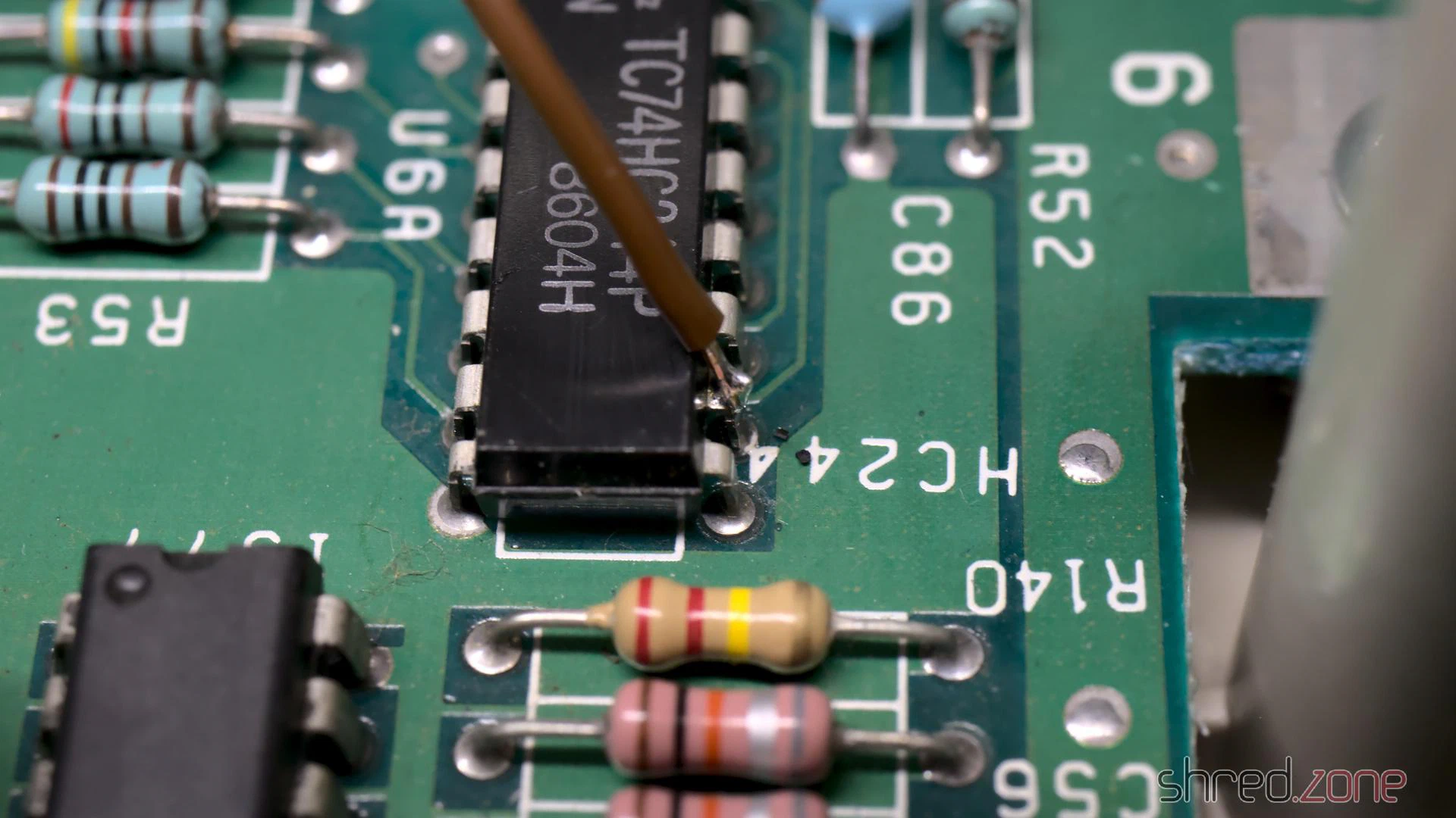
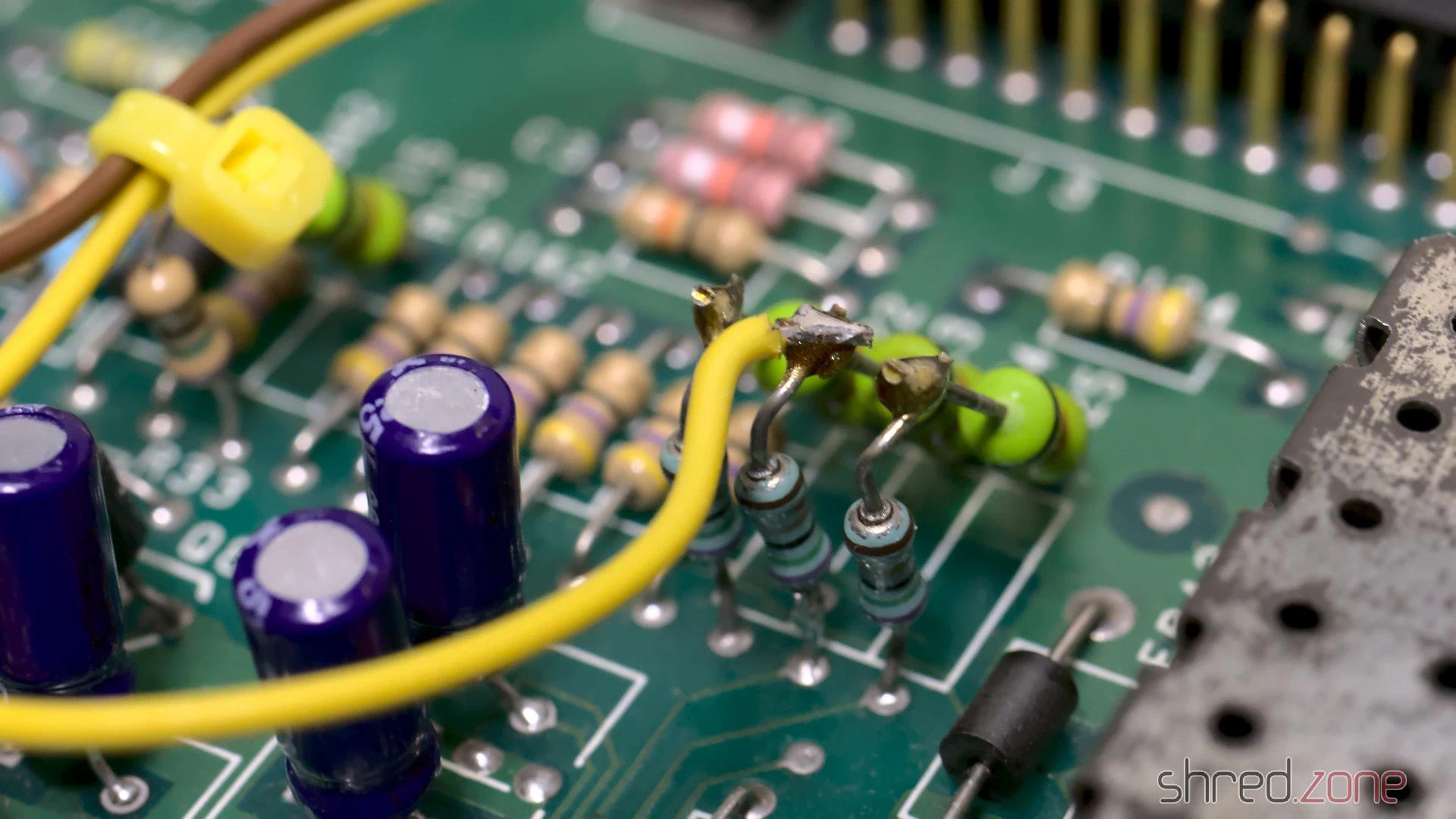
The other end of the two wires are connected to the respective CSYNC and RGB pins of the OSD header of the GOEX drive. It is also possible to control the GOEX drive with the Amiga keyboard, but I didn’t want to do more hardware modifications, especially if it involves soldering wires directly to one of the CIAs. I prefer that I still have to touch the floppy slot for changing floppy disks, even if it’s just virtually.
Reassembly
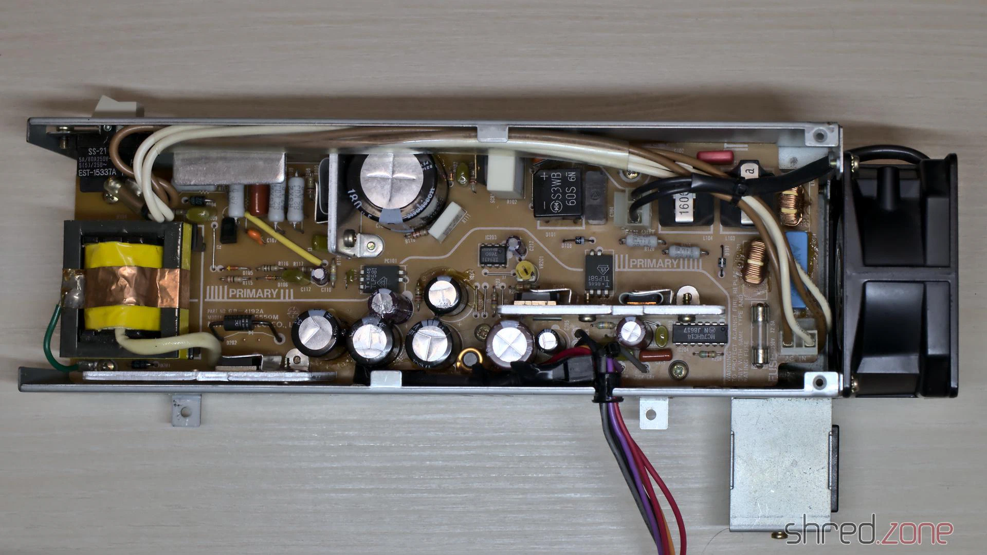
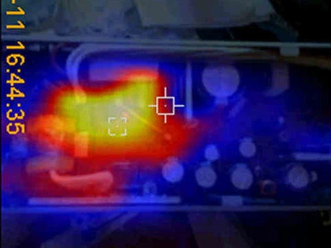
A trained technician should definitely overhaul the PSU, to avoid damage to the hardware or spectacular explosions of safety capacitors. @DingensCGN of the a1k.org forum did an excellent job there. He replaced all electrolytic capacitors, and did a full load test including checking the temperatures of the components with a thermographic camera. A big shout-out to him!
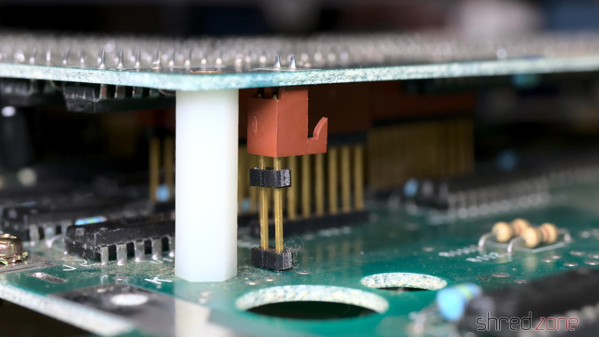
This Amiga has a separate piggyback board, which I had removed for cleaning and re-capping. It is connected to the mainboard by some headers at different places, which makes reseating it a bit tricky. It is crucial that all headers are properly connected.
For the GOEX drive, I designed a 3D printed frame for the Amiga 1000. It holds the drive in its correct position, and also holds the original eject button so the hole in the front is closed. My intention is that the GOEX drive should be as invisible as possible, so the original look of the Amiga 1000 is maintained. I guess I managed that.
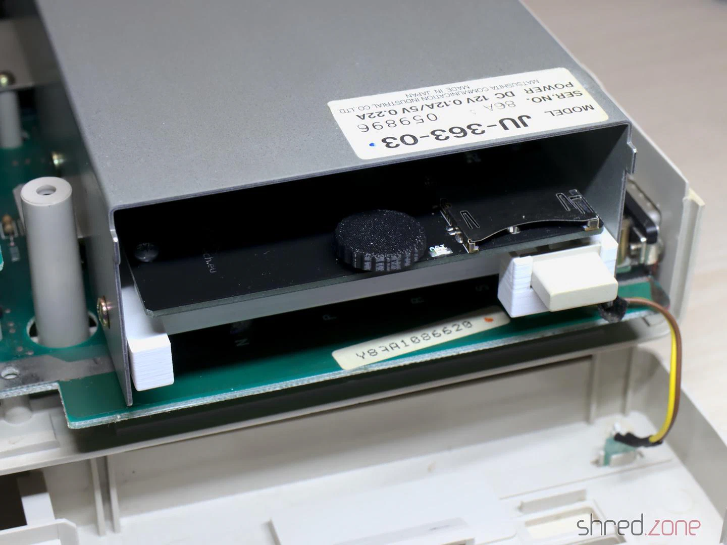
And that’s it. The system is fully assembled now.
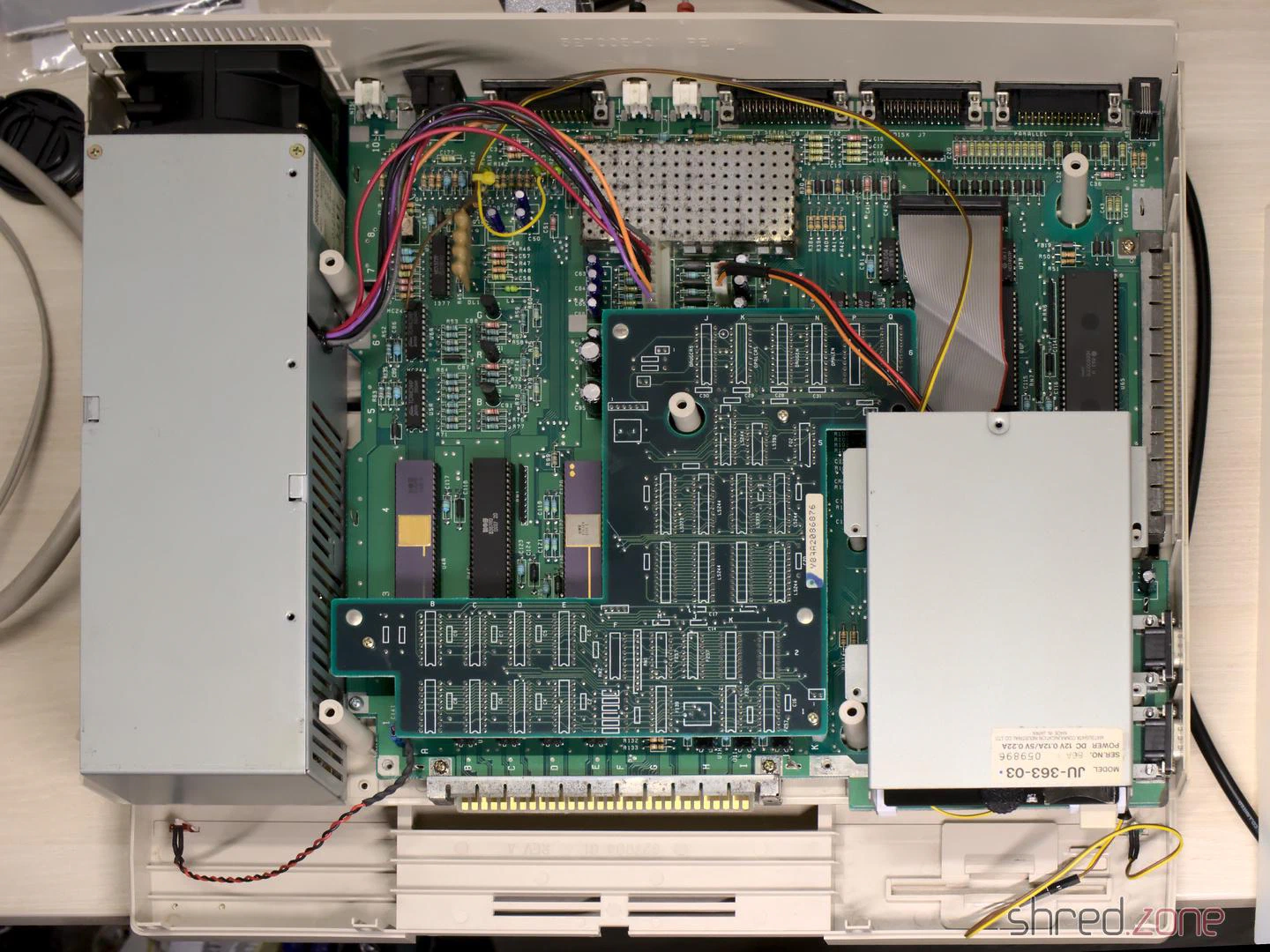
I mounted the top shield, attached the front plate, closed the case, and connected the 256KB memory expansion to the front slot.
And then came the moment of truth. I flipped the power switch. The system started up. I expected the 230V PSU fan to be rather noisy, and was very surprised that it is almost inaudible, and could easily compete with modern ultra-silent 12V fans of the same size.
Then the famous Kickstart screen appeared, together with the FlashFloppy OSD.
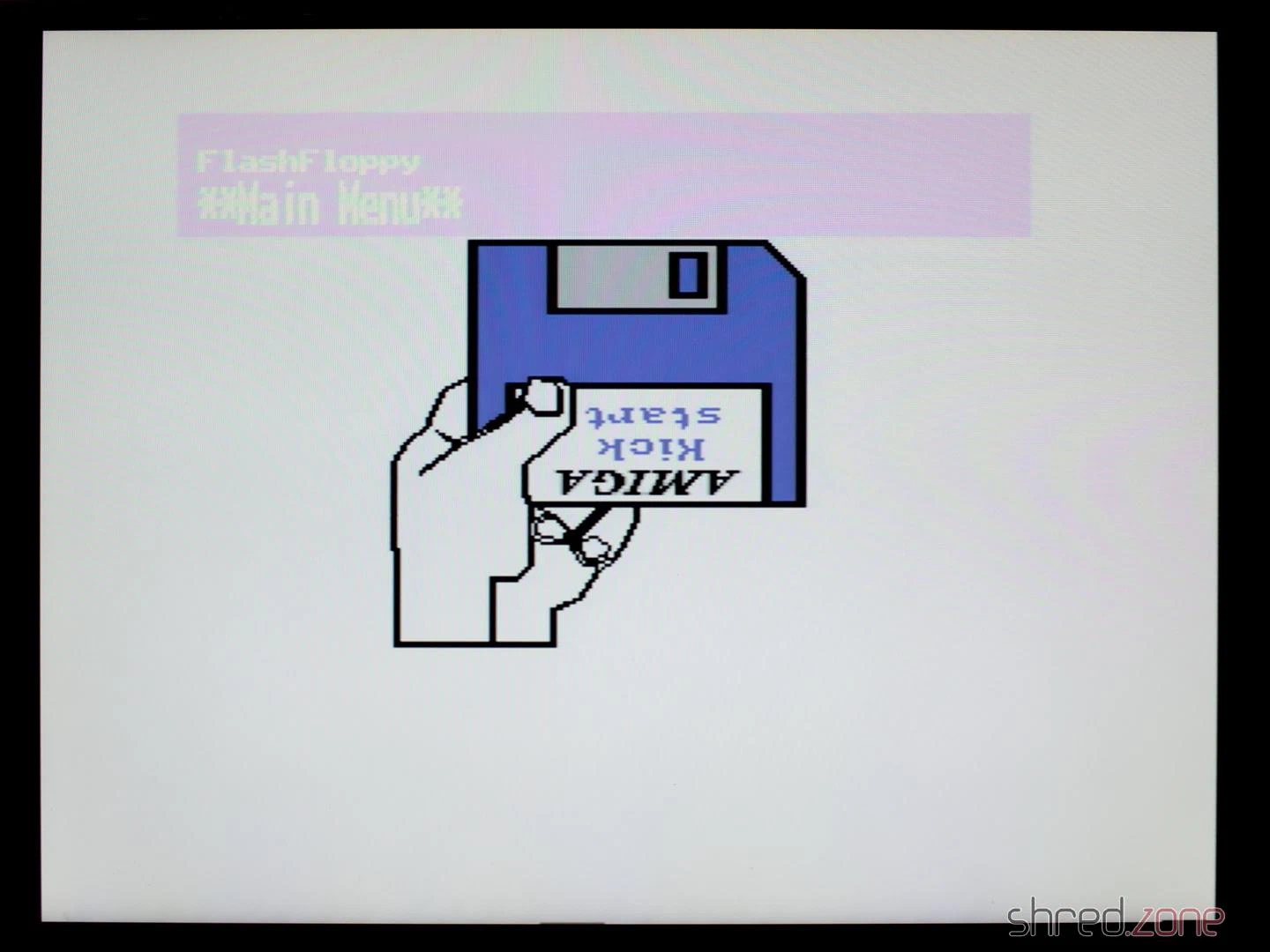
I loaded the Kickstart ADB file from the GOEX drive, and after that I changed to the first disk of the famous Red Sector Megademo. The Amiga just dutifully loaded it.
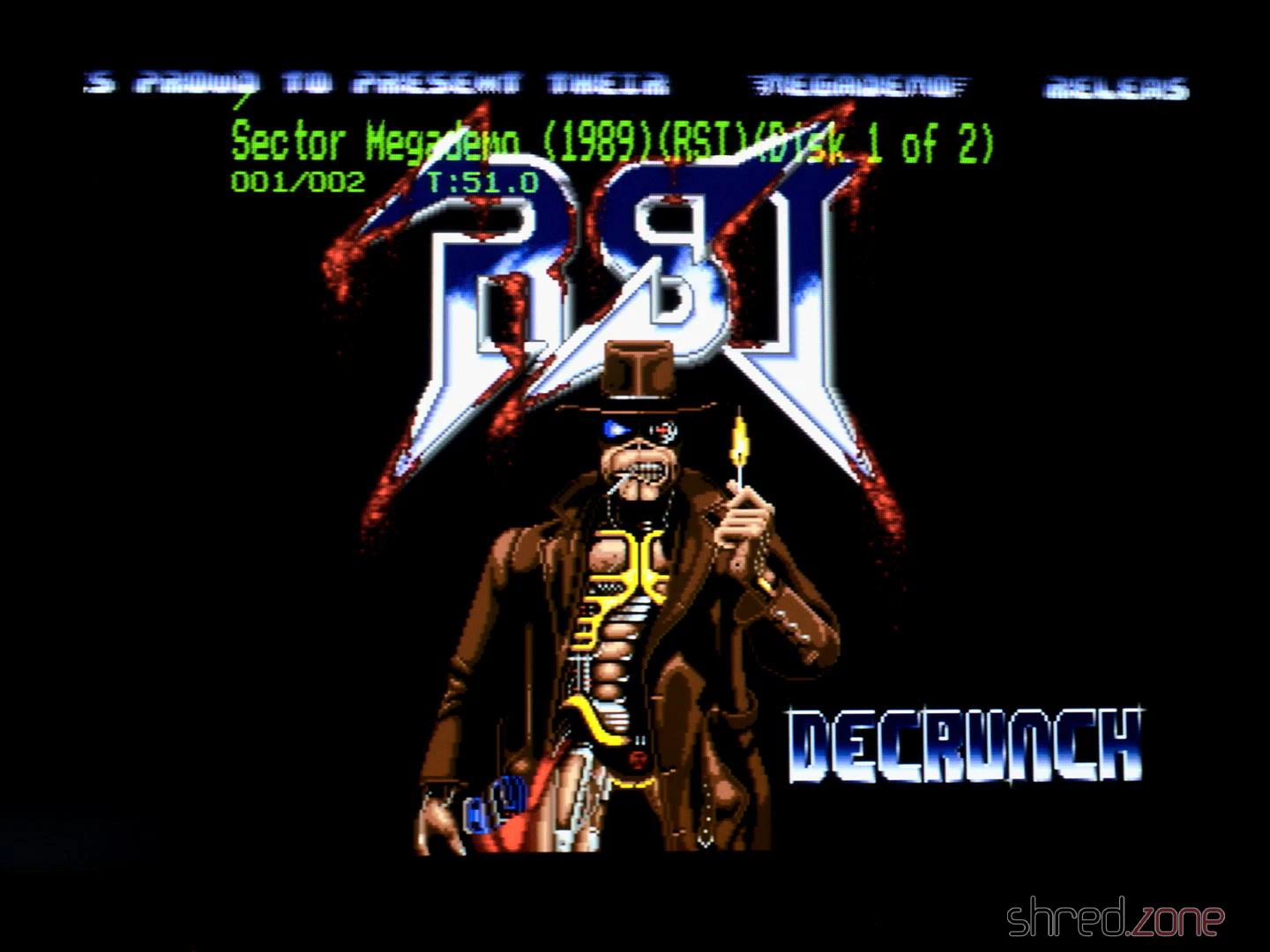
Everything ran smoothly! The green color of the OSD certainly adds a lot to the 1980s retro feeling of that machine. It looks quite like those OSDs on old TVs or VCRs. 😆
Configuring FlashFloppy
There were two things that were bugging me. The first was that I’d like to run a cold start of the machine as simple as possible, so the GOEX drive should always select the Kickstart ADF first when the system is powered up. The second was that the OSD was shown on the screen for much too long. It should disappear a few seconds after disk inactivity.
Both is easily configured. First, a directory called FF needs to be created on the SD card. Then a FF/FF.CFG file needs to be created, having this content:
image-on-startup = static
display-off-secs = 5
A second file called FF/IMAGE_A.CFG contains the file name of the Kickstart ADF file on the SD card.
Welcome!
And that’s it! I am, and have always been, a big fan of the Amiga. I learned a lot on my Amigas, and they were the foundation of my career as professional software developer.
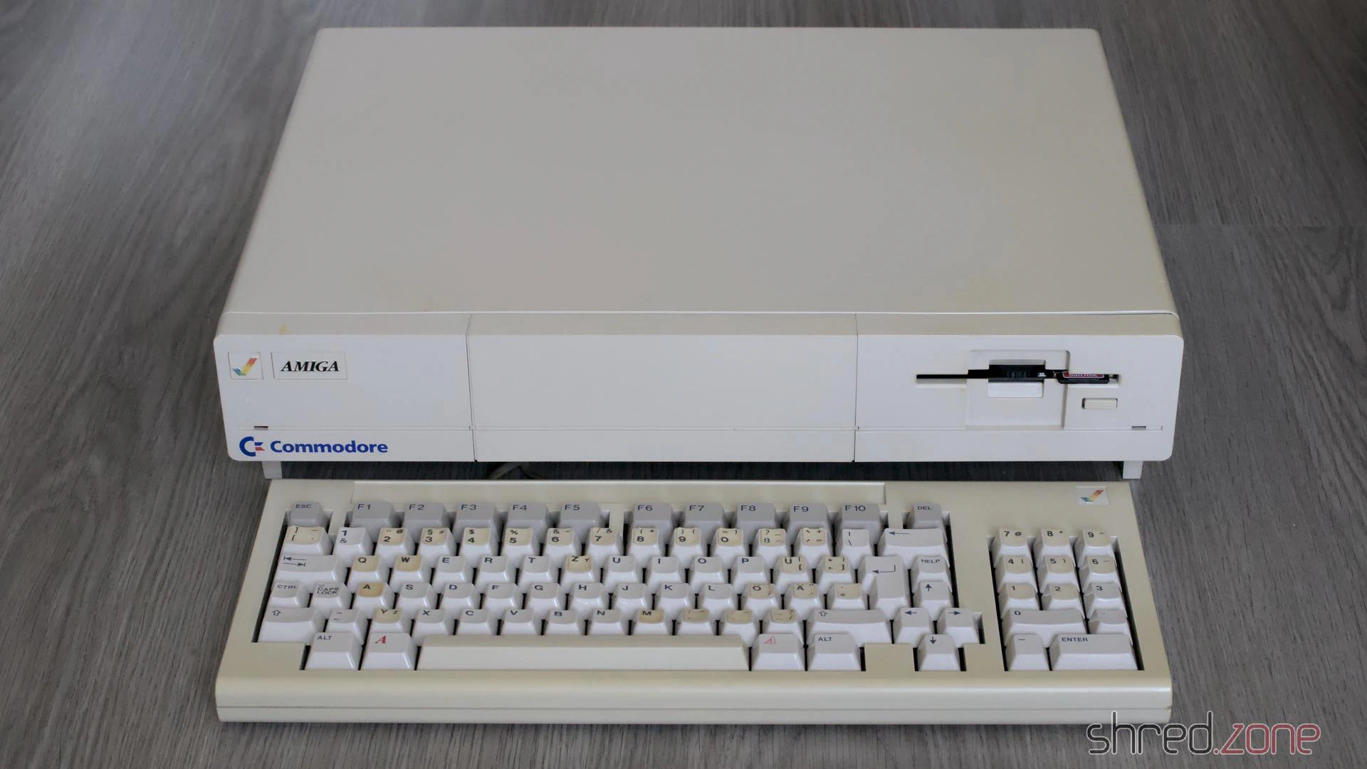
I always considered the Amiga 1000 to be the pearl of my Amiga collection, and I am happy and proud that I got the chance to own such a beautiful machine now.
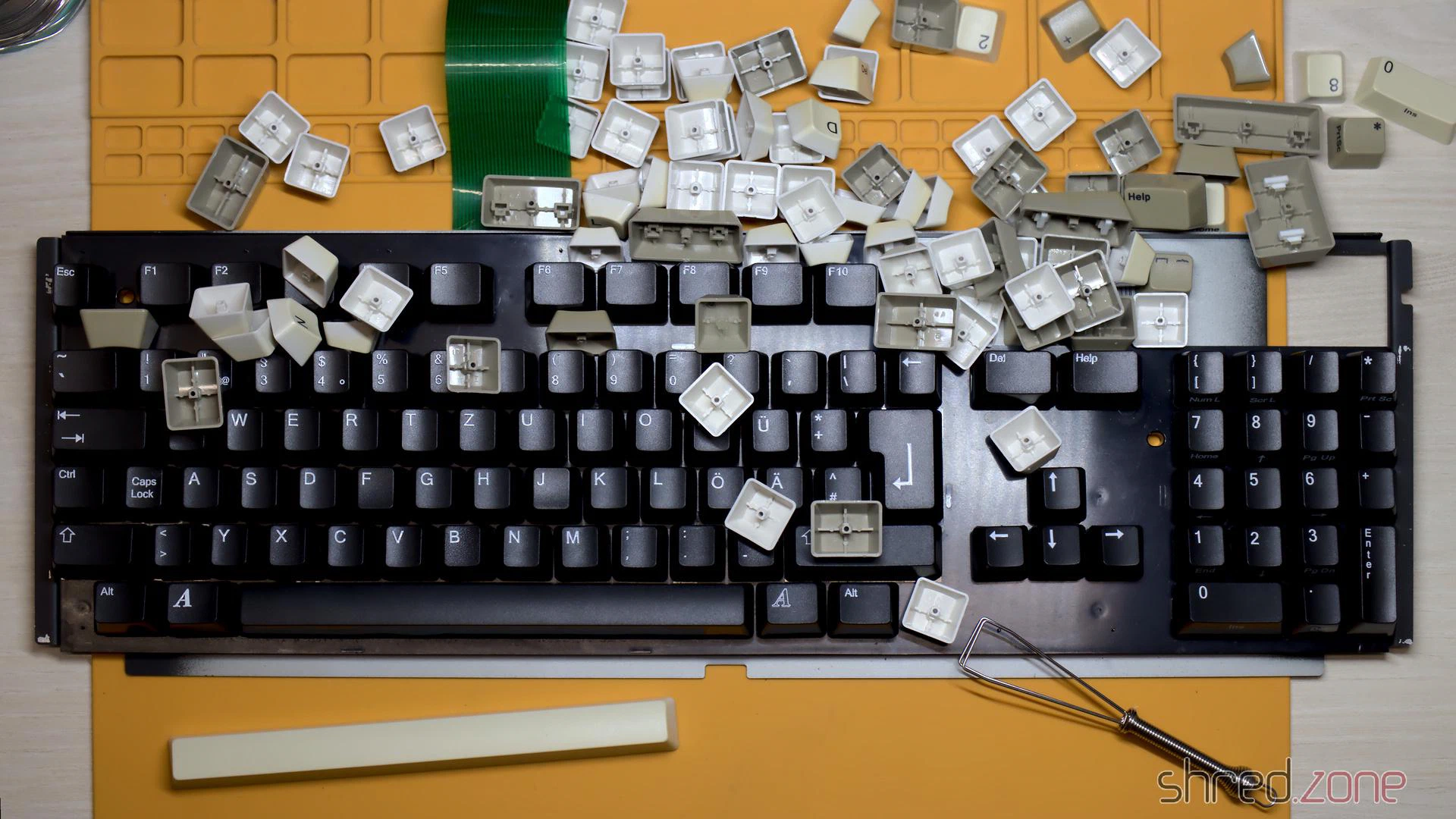
In this second part, I will take care about the keyboard. I expected that it would be the usual procedure: Cleaning the key caps and case, whitening the yellowed parts, dusting off the keyboard frame.
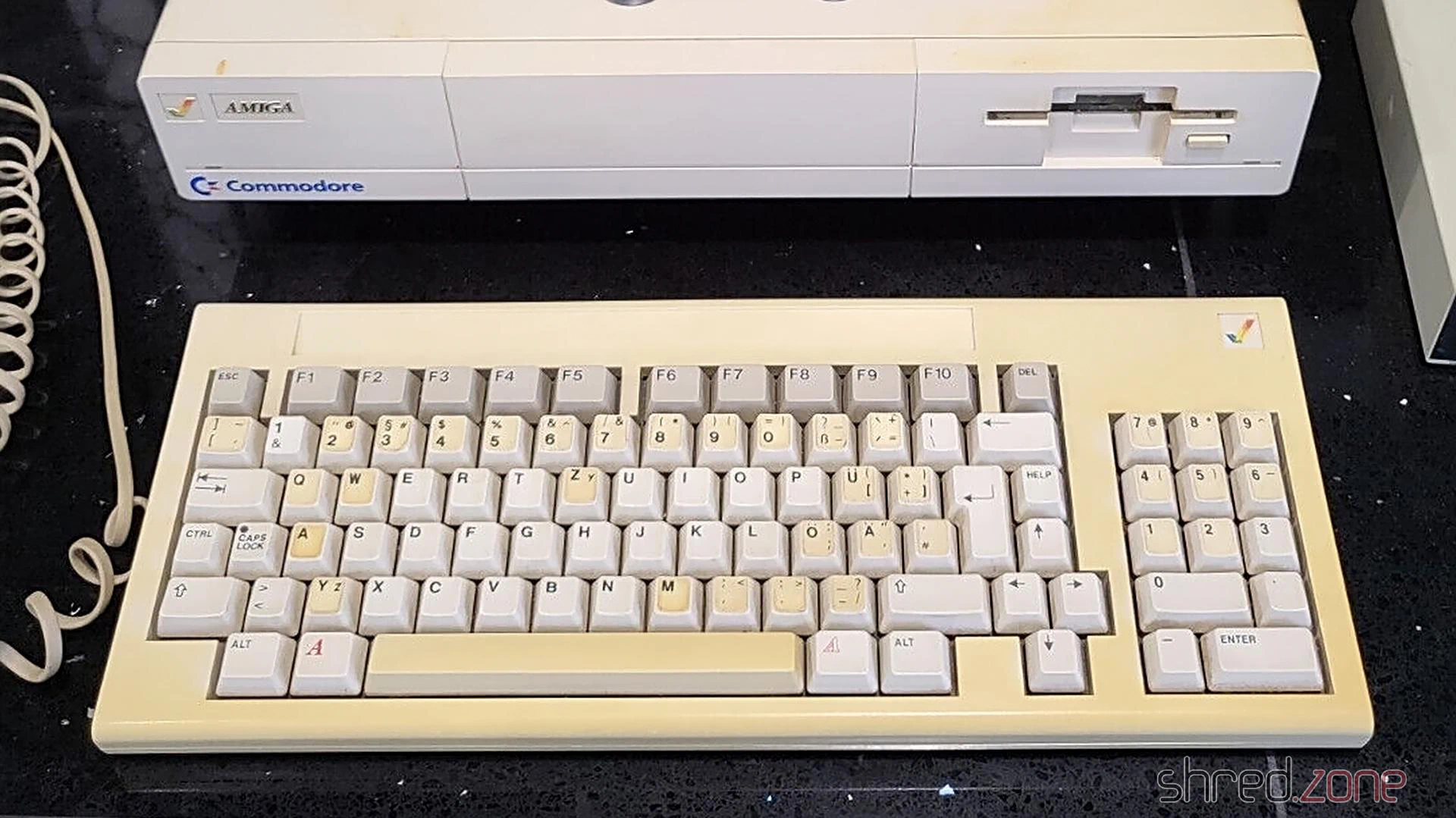
However, this time it wasn’t that easy.
The trouble started when I pulled off the key caps, but also pulled out the plungers of three keys. Fortunately this can be repaired, as the switches are easy to maintain. More about that below.
Keyboard Cleaning
The key caps were cleaned in an ultrasonic bath with a drop of rinse aid, and then brushed with a soft toothbrush.
Below the key caps, there is the keyboard frame where the switches are mounted. I found the usual filth that you would expect there after almost 40 years, but there was also flash rust, a crusty dirt layer, and… dead insects. I went outside and brushed off the insects and all the other loose dirt. Then I went back inside, and sprayed the frame with IPA, in an attempt to clean off the crust. The room immediately filled with an unhealthy stench of dust, dirt, and insect excrements. 🤢 Also, my attempts to remove the flash rust with a fiberglass pen wasn’t really successful. There was too much of it.
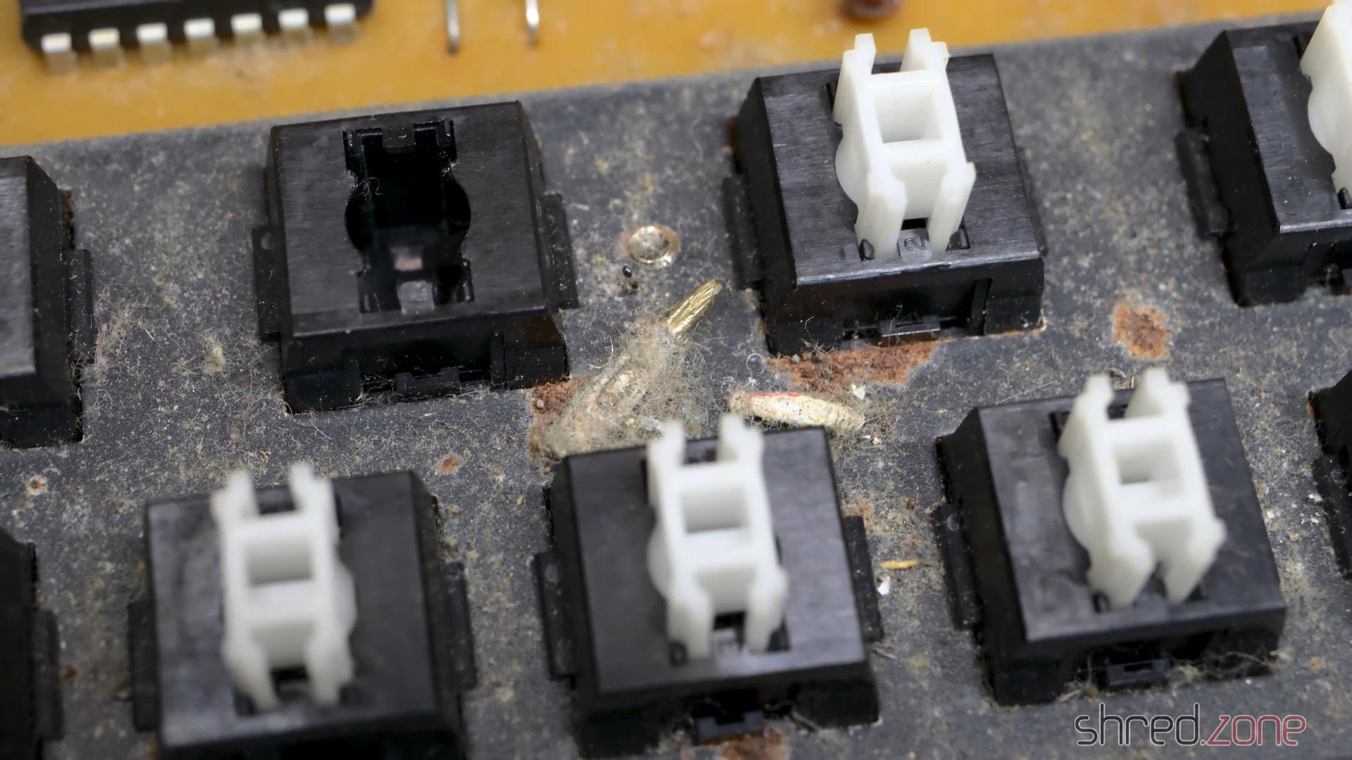
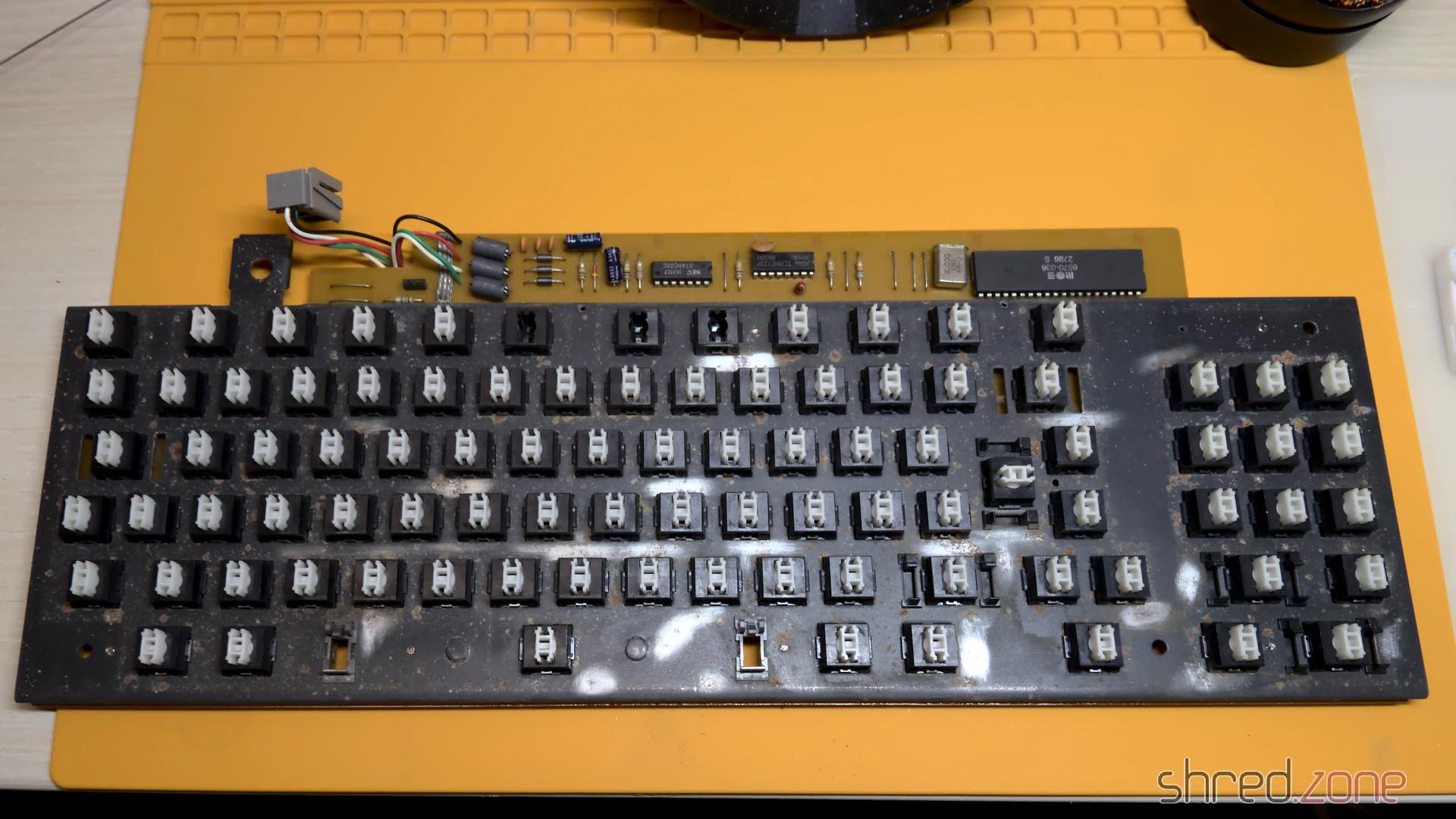
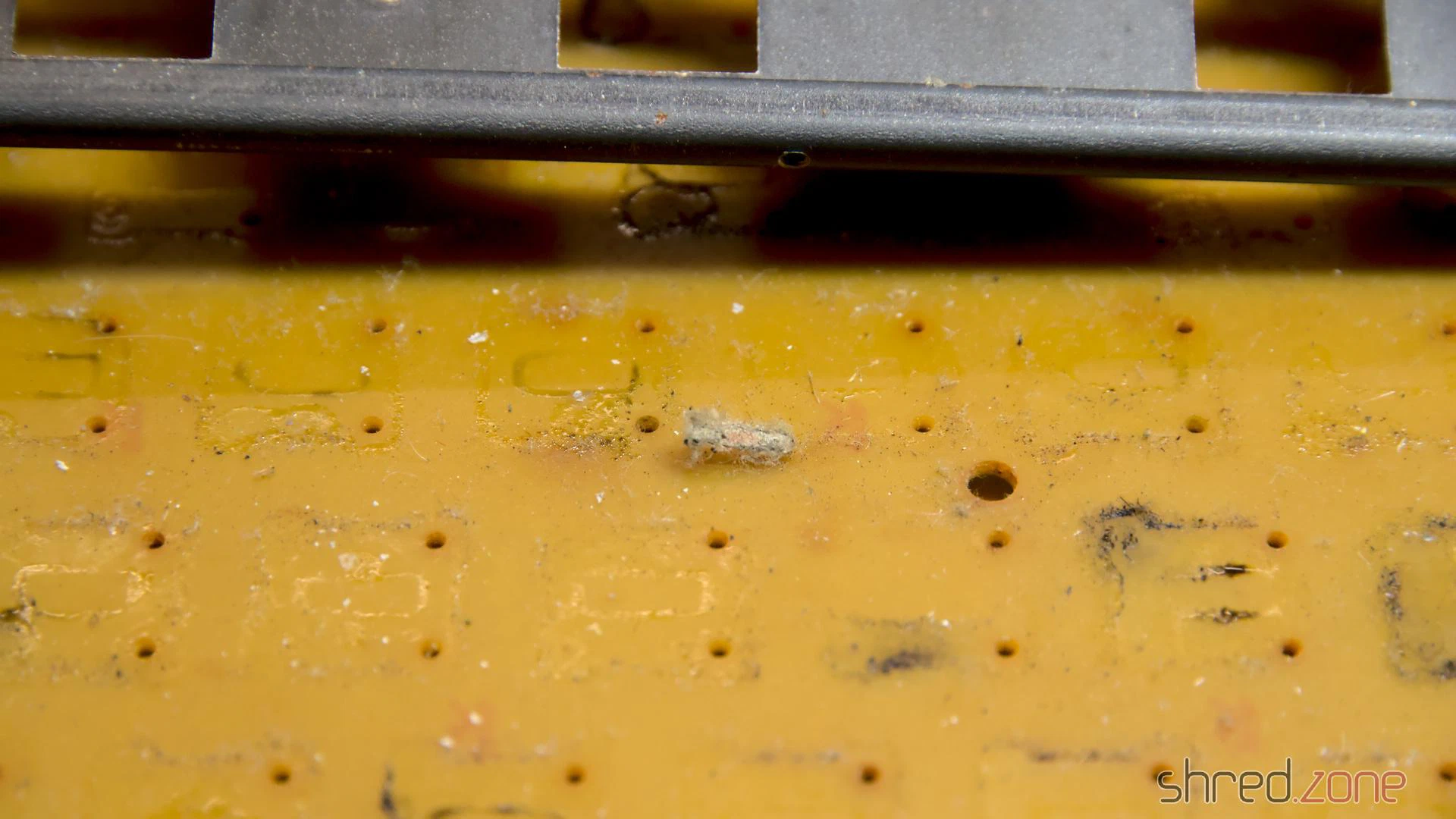
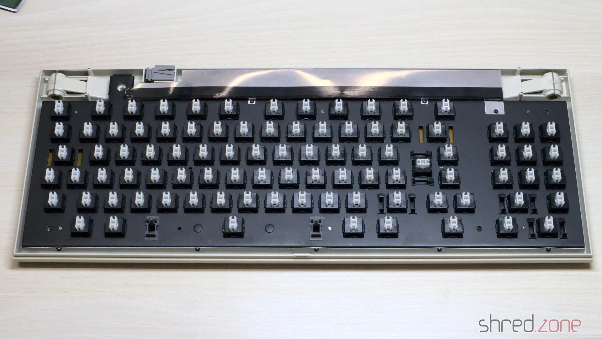
I wanted to avoid that I had to refurbish the frame, because it can only be removed after unsoldering all 91 switches (and one LED). But there was no other way to do it. So I unsoldered everything and removed the frame. On the PCB, I found dried stains from a liquid (maybe from a soft drink that had been spilled over the keyboard), and more dead insects. It confirmed that it was the right choice to go all the way.
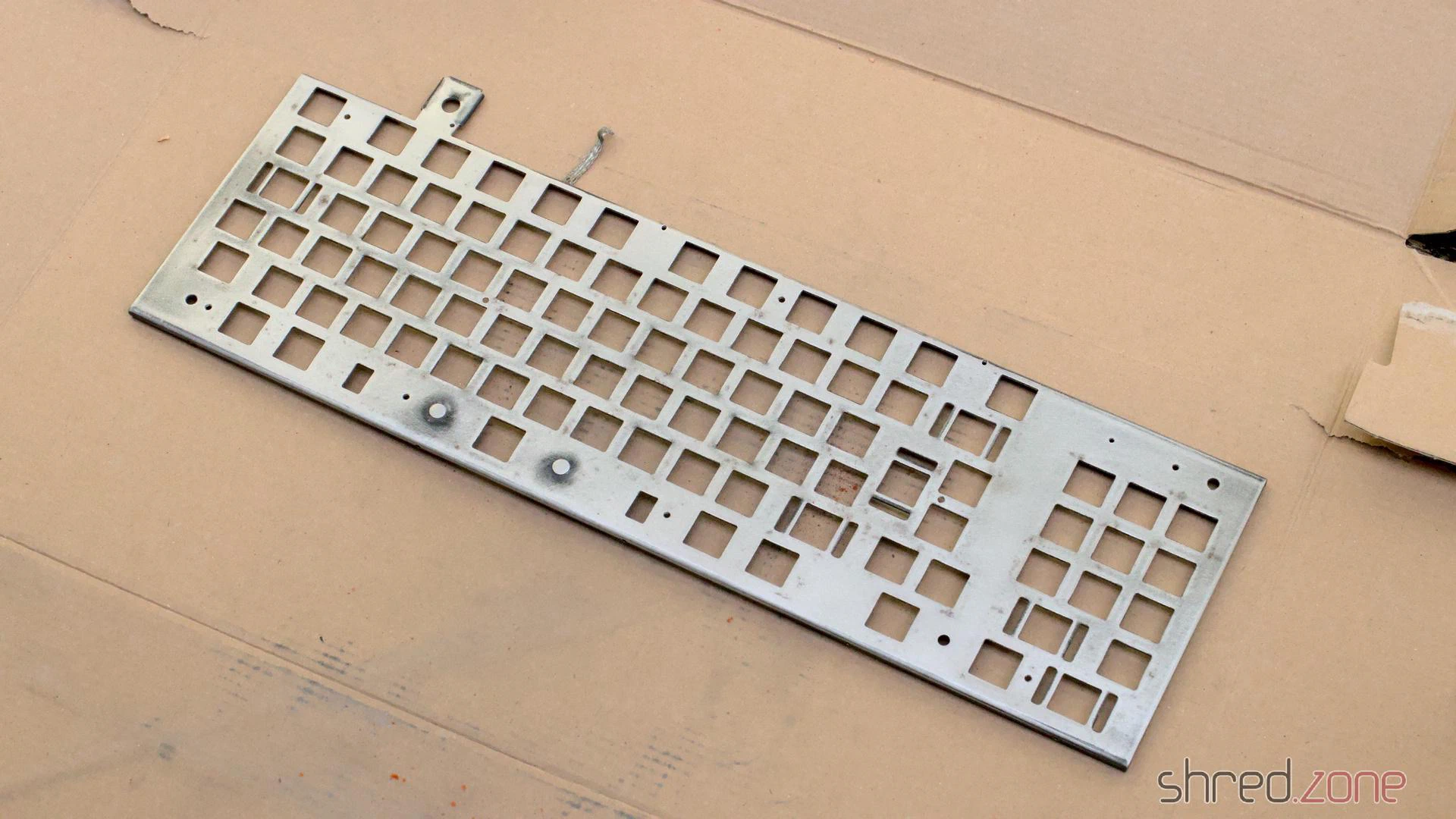
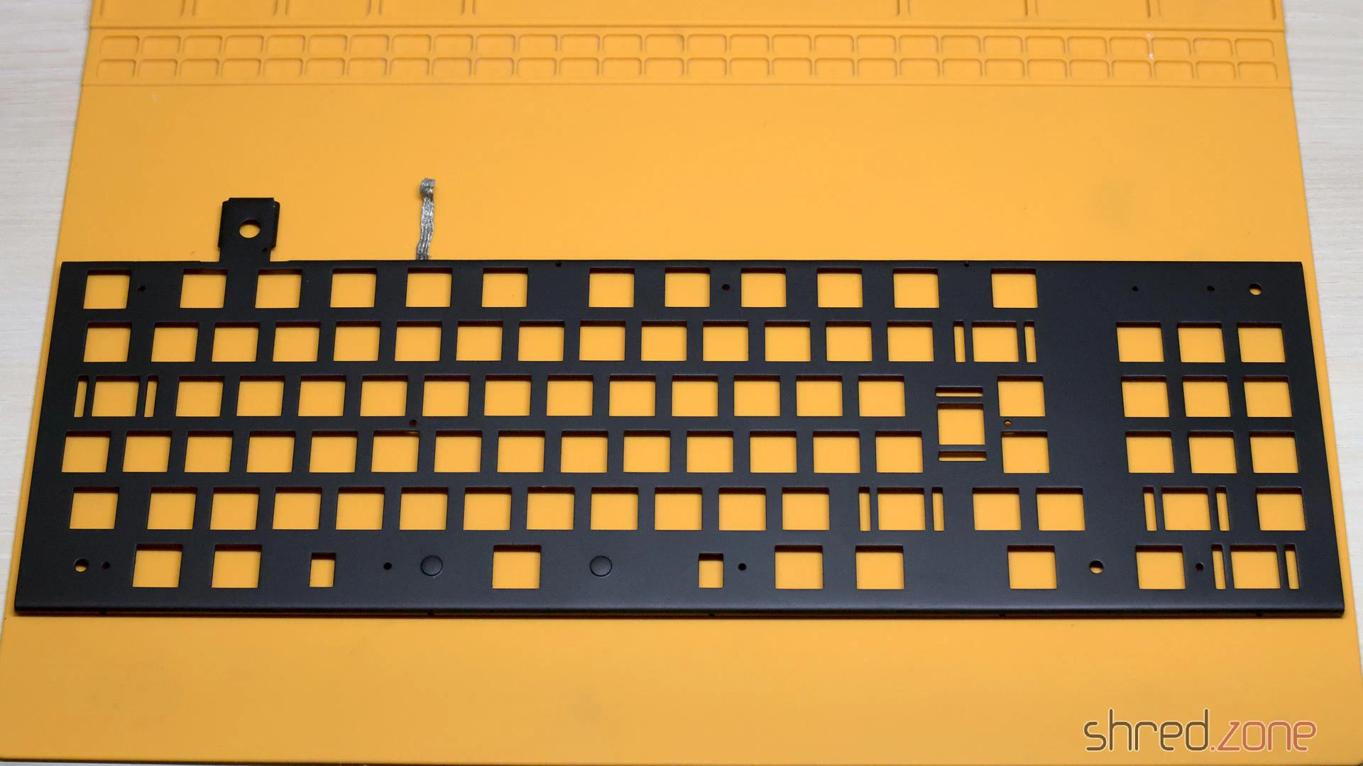
I sanded down the old paint and the dirt crust from the frame (outside, and wearing a good filter mask). Then I spray-painted it in a matte black. It’s looking so much better now.
Refurbishing the Switches
The next bad surprise came when I was about to reassemble the keyboard. I tested all 91 switches for continuity when closed, but found only about 40 of them actually working. When I depressed the other keys, they either did not close the contact, or the plunger got stuck, or both.
The switches that are used in the Amiga 1000 keyboard are Mitsumi Type 2 tactile switches. They are out of production by today, but they are easy to maintain. After trying the best approach with a couple of switches, I found the following procedure to be most successful.
The switch can be opened by putting a kind of blade (like the head of a flat screwdriver, or flat pincers) into the latch on both sides, and then carefully removing the cap with a blade or another screwdriver. The switch consists of four parts: The cap, the plunger, the switch plate, and the base.

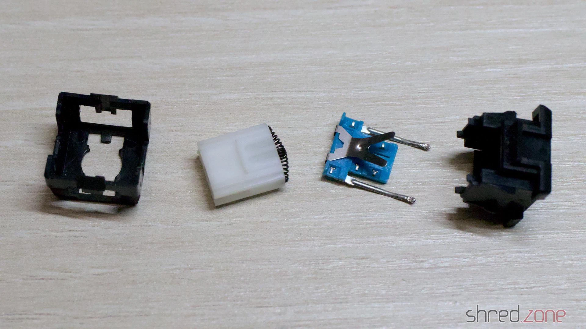
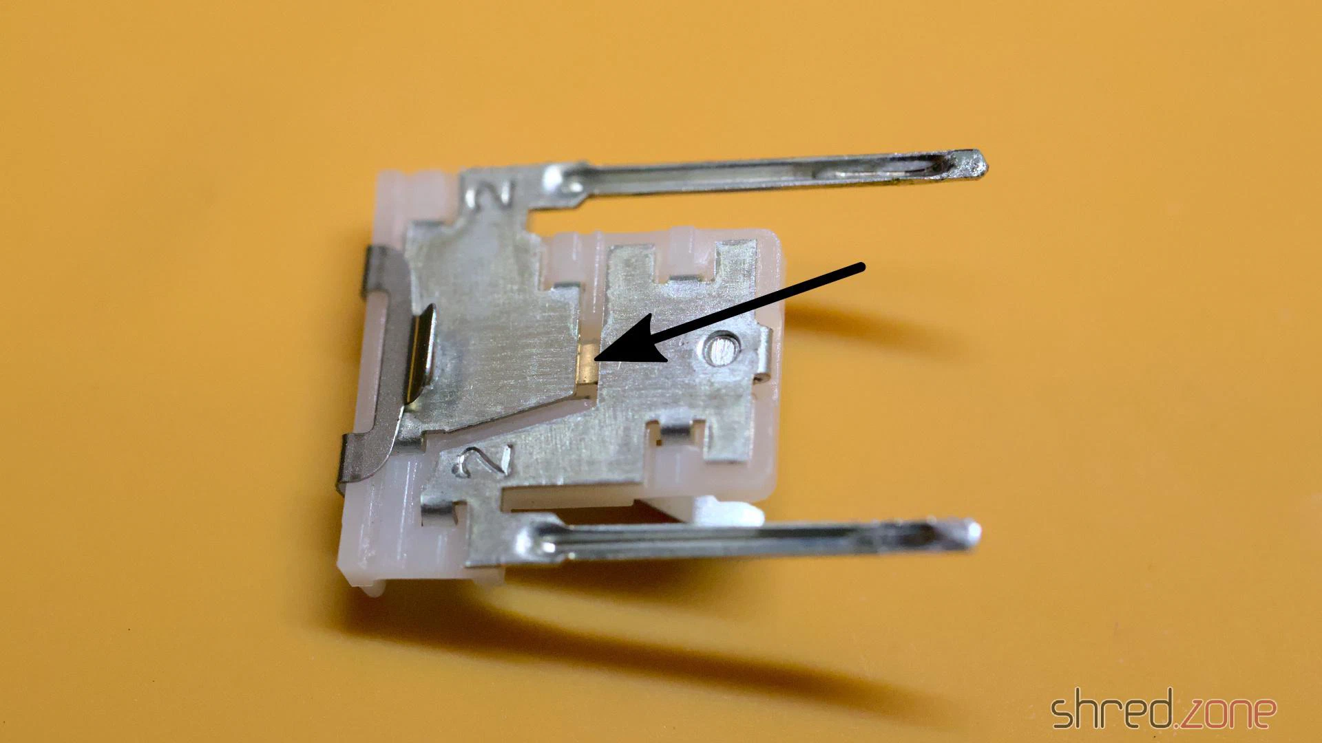
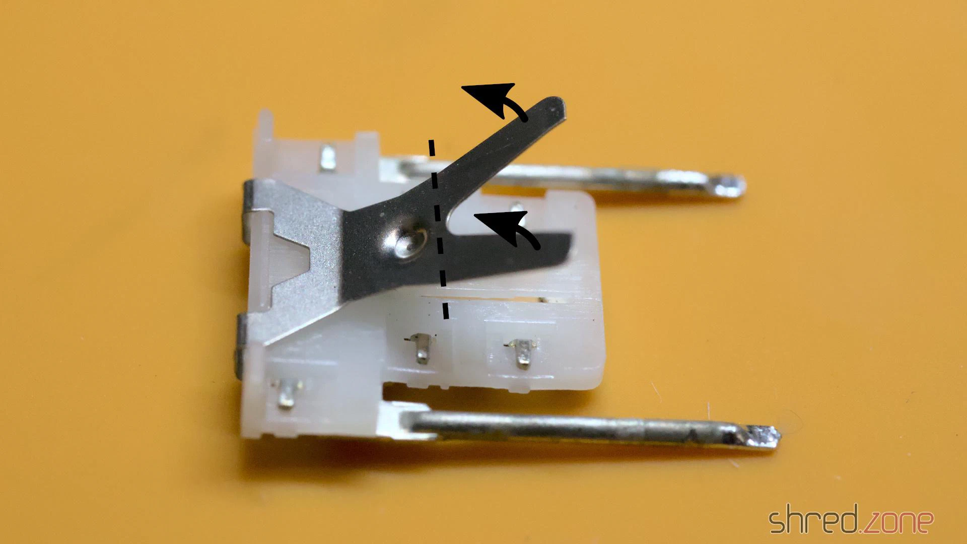
I cleaned the switch plate with contact cleaner spray. I also bent up the legs of the lever a tiny bit, so it will give a bit more pressure on the switch when the key is depressed.
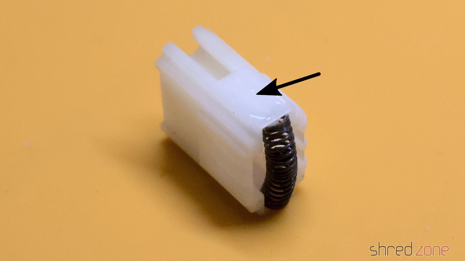
Finally, I applied a bit of silicone grease on both small sides of the plunger. It is important to use a very very tiny amount! If too much is used, the key will feel sluggish or might even get stuck. If in doubt, better skip this step.
After that, the switch was reassembled and tested again. If it was still getting stuck or didn’t close the contact properly, the process was repeated.
It was a lot of work and a monotonous task, but at the end I could make all the switches work again.
Whitening
The keyboard case was cleaned in soap water. After that, the case (and the yellowed space bar) were exposed to the July sun for whitening.
The result is quite good, but on some parts a bit of yellow is still visible. I guess there would be an even better result if I would use peroxide, but I have no experience with that, and am not too keen to gain it with this rare keyboard.
The labels on some of the keys are still yellow, and wouldn’t get any whiter in the sun. I guess that I will have to replace them with new labels some day.
Reassembling
With every parts cleaned and whitened, the keyboard was ready for reassembly. I pressed the key caps back on the keys, mounted the shielding, and then put the keyboard frame back into the case.
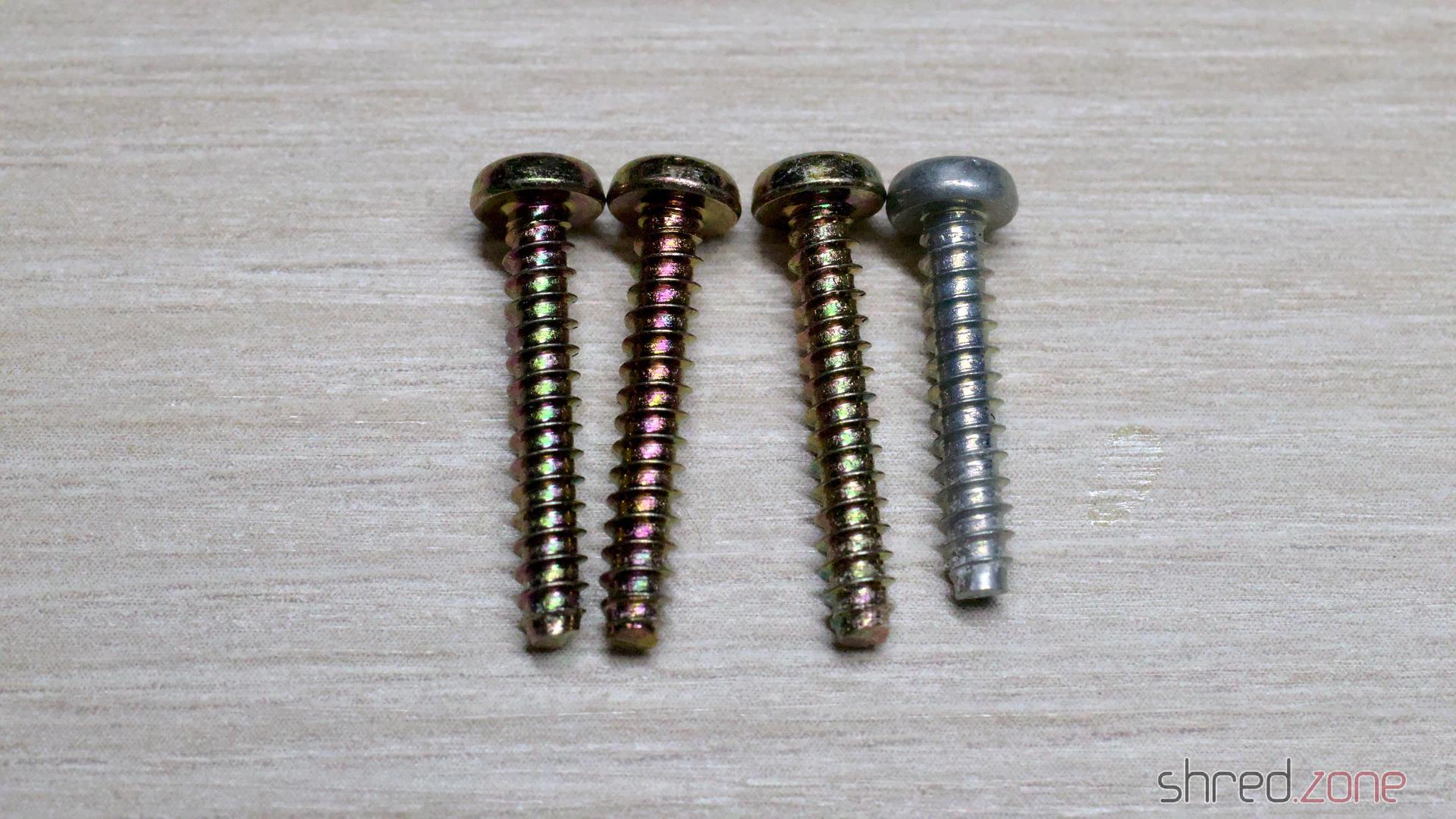
Take care when closing the case: One of the four screws is a bit shorter, and maybe also has a different color. This single screw must be used for the upper right hole.
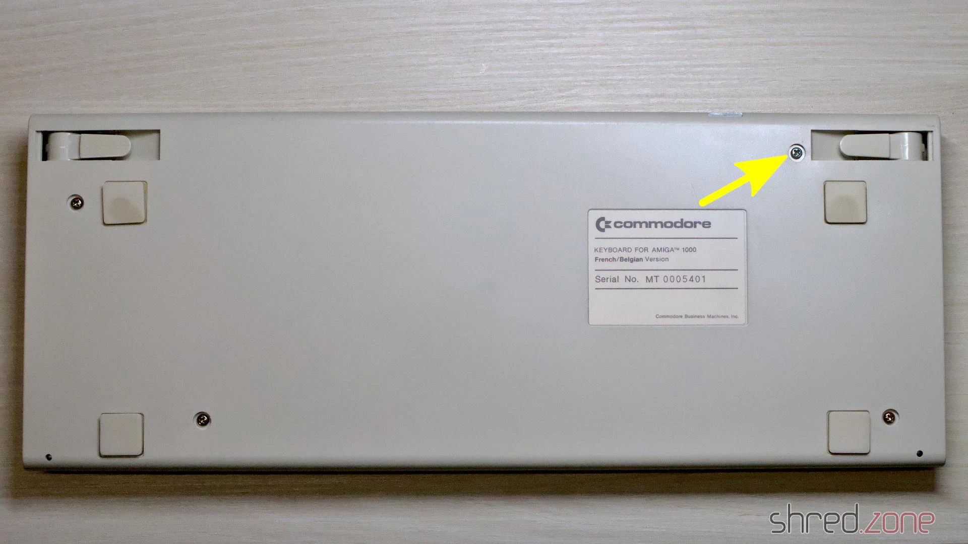
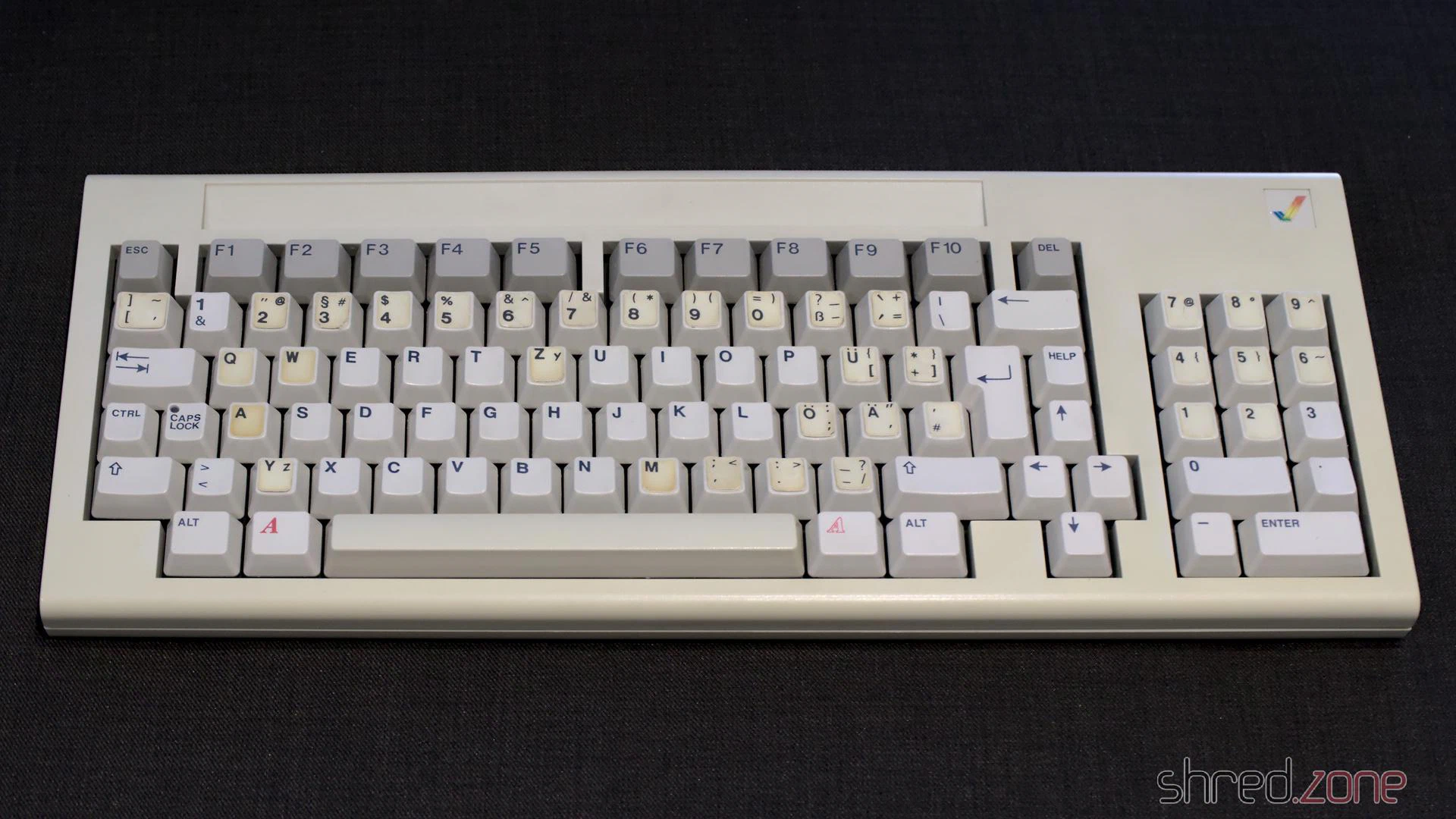
The keyboard restauration is completed now!
In the next part, I will reassemble the main unit, and have a first test. Is the Amiga still working?