In the third and final part, I am going to futureproof the Sidecar and finally test it. Will it work after all the hours and patience I put into the repair?
Gotek Drive
I probably only own a single 5¼" floppy disk, back from my time at school. However the Sidecar won’t do much without floppies, so I decided to add a Gotek drive.
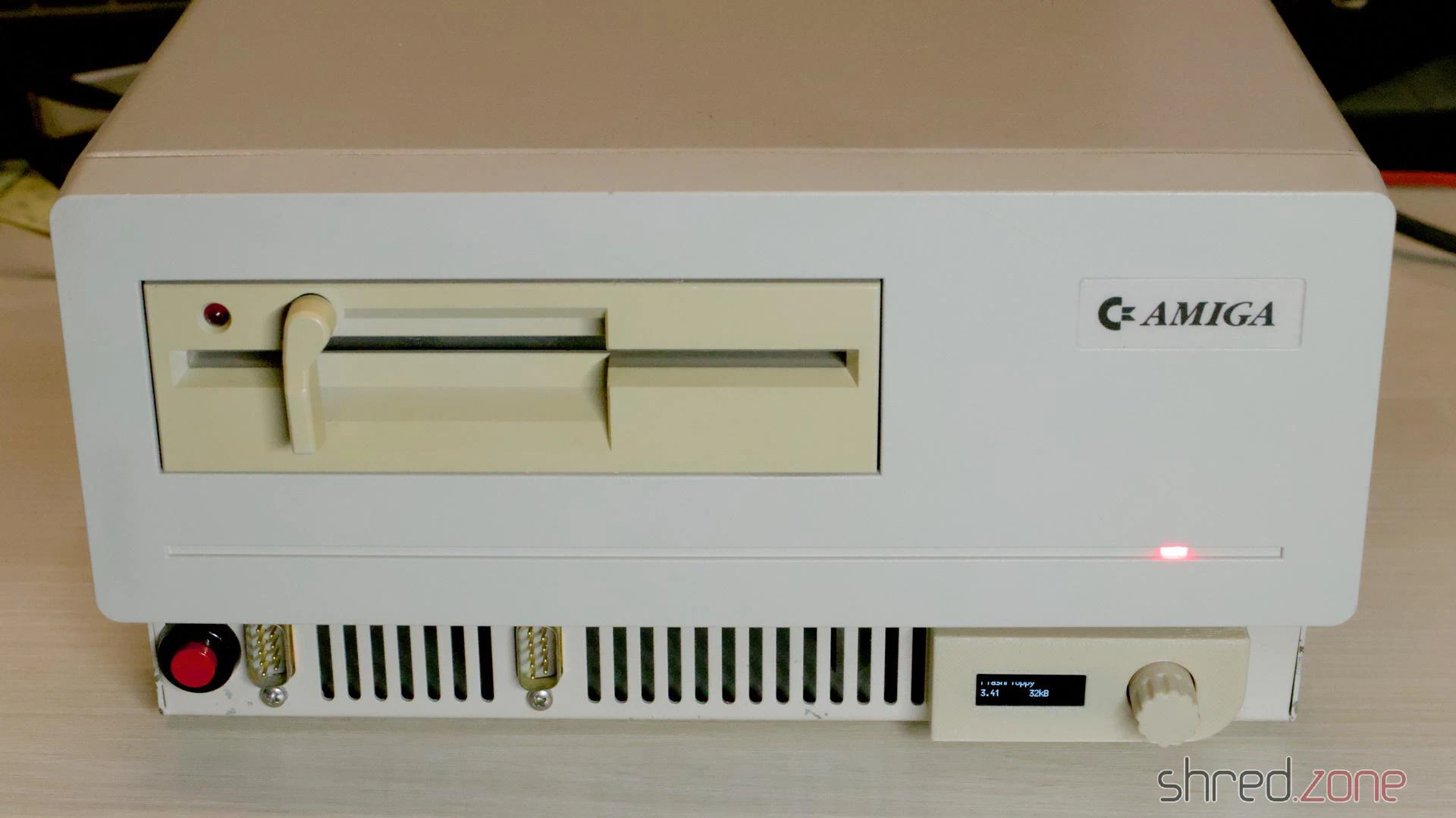
The modification must be fully reversible, and I also wanted to keep the original look of the Sidecar with its floppy drive. I designed a Gotek bracket for the expansion slot and a control panel with OLED display and encoder. The panel is screwed to the front air grille, so no holes need to be drilled into the case.
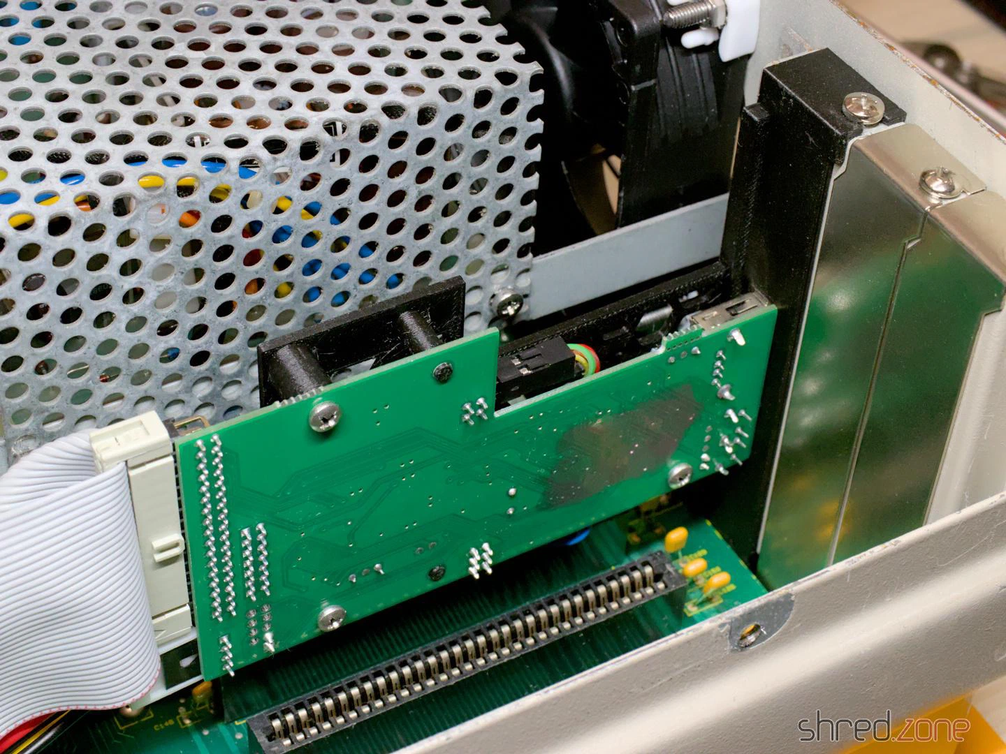
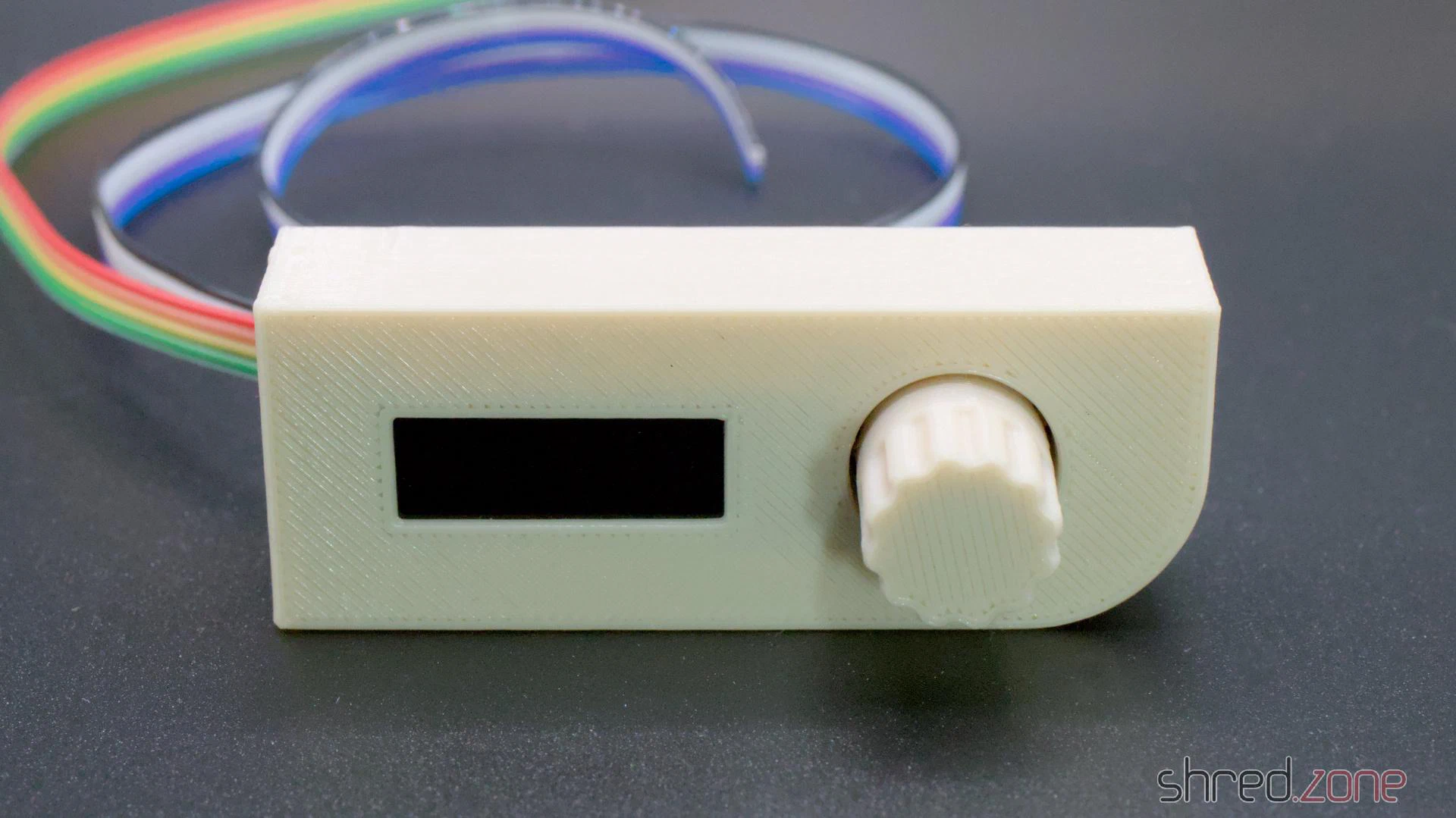
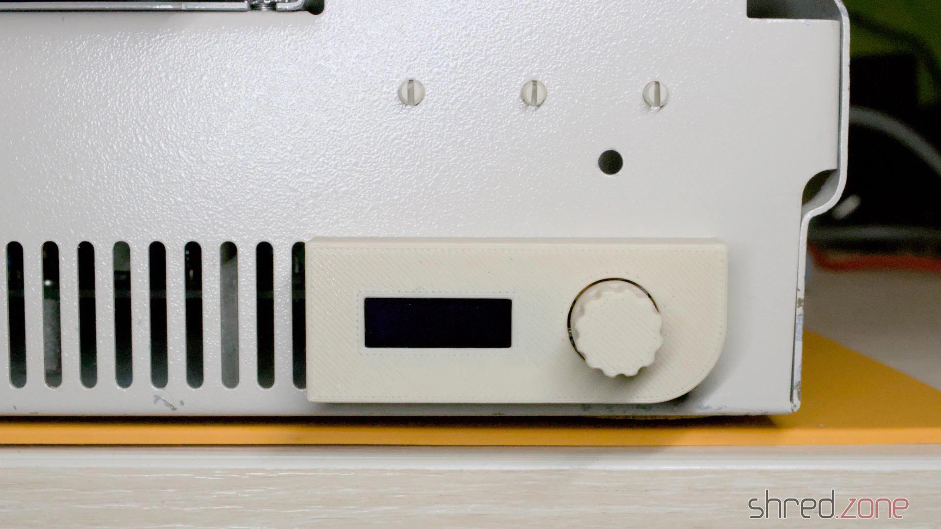
I made a new flat cable to connect the Gotek drive and the floppy drive to the mainboard. The Gotek drive is supposed to be drive A:, while the floppy drive should be B:. Both drives can be configured with jumpers, so there is no need to make a twisted floppy cable.
First Test Run
For the first test run I did not connect the Sidecar to the Amiga yet. If something on the Sidecar was badly broken, it wouldn’t damage the Amiga that way.
So I turned on the power. The fan spun up, the power LED lit up, but nothing else happened. Well, since the Sidecar is not meant to work as a standalone PC, this is probably normal. At least there was no magic smoke and no smell of smoldering electronics. I took the opportunity to check the voltages, and they were all correct and stable.
Things looked pretty good.
Making a Janus Workbench
The Sidecar is controlled by the Amiga. It has no connectors for a monitor or keyboard. Fortunately, the driver disk can still be found on the internet. For installation, I first had to make a copy of the original Workbench 1.2 disk, and then run the installer from the install disk.
On my Amiga 1000 however, the installation failed because the RAM disk ran out of memory. My Amiga is equipped with the maximum 512KB of Chip RAM, so it was supposed to work. I tried it multiple times, but always got this strange error.
I gave up and set up a UAE instance of an Amiga 500 with Kickstart 1.2 and 2 MB of Fast RAM. On this machine I was finally able to complete the installation.
The installer is a bit strange and not based on the Amiga installer tool that came later. It is best to use the default options and wait patiently for each step to complete.
Test Runs and Fixes
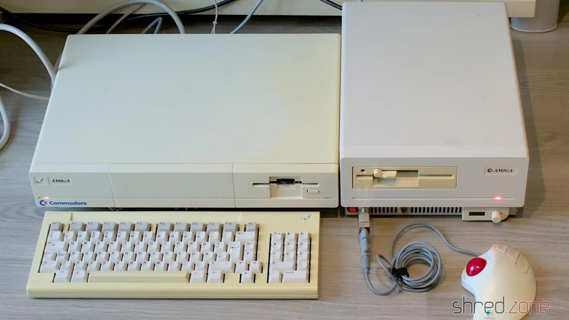
Connecting the two devices isn’t easy and can damage the hardware if done wrong. First I unplugged the power cords from the Sidecar and the Amiga. Then I connected the Sidecar to the expansion port of the Amiga. It’s a bit tricky to find the correct position, but the joystick and mouse connectors are a good orientation guide. There is no need to use force.
The Sidecar also has a power cord extender. I plugged it into the Amiga’s power connector and made sure that the Amiga’s power switch was turned on. Both devices can now be controlled with the power switch of the Sidecar.
CAUTION: You must never turn on power to the Sidecar unless the Amiga is already powered up. Otherwise you will damage your Amiga! You can avoid this problem by using the power cord extender and making sure that the Amiga’s power switch is always on.
Now it was time for the truth. I booted the Janus Workbench I prepared above, but got a Guru Meditation during startup. I tried other driver versions and other floppy disk images I could find, but it always ended with the flashing red square.
Fortunately, the hardware registers are well described in the A500/A2000 Technical Reference Manual, Section 4.1. The description is for the A2088XT bridge board, but it is very similar to the Sidecar.
I quickly hacked some small diagnostic tools. They confirmed that the 128KB bridge RAM and the six replaced bus drivers were working fine.
I also found that the PC reset did not work. I only managed to actually reset the PC once. It played a chime and then actually accessed the MS-DOS disk I had in the Gotek drive. This means that the PC side was basically working, but the bridge board was having problems.
There are four PALs and three FPLAs on the upper board. The PALs have a specified memory retention time of about 20 years, which is long past. I remembered that the PALs on my MaestroPro were already having memory problems due to old age.
The fusemaps of the PALs can be found on the Amiga Wiki. I replaced the four PALs with modern ATF16V8C-7PU GALs.
After that I was able to reset the machine reliably. The Guru Meditation was also gone when I booted the Janus Workbench. But the Sidecar still refused to come back out of retirement. What I got now was a garbled PC screen.
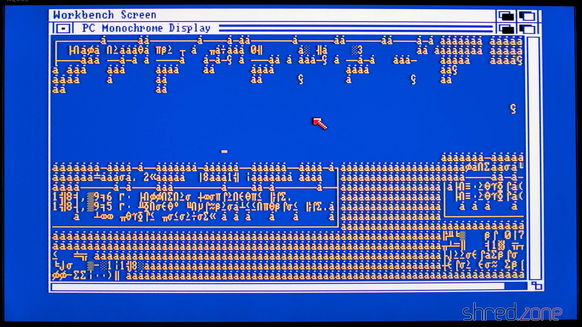
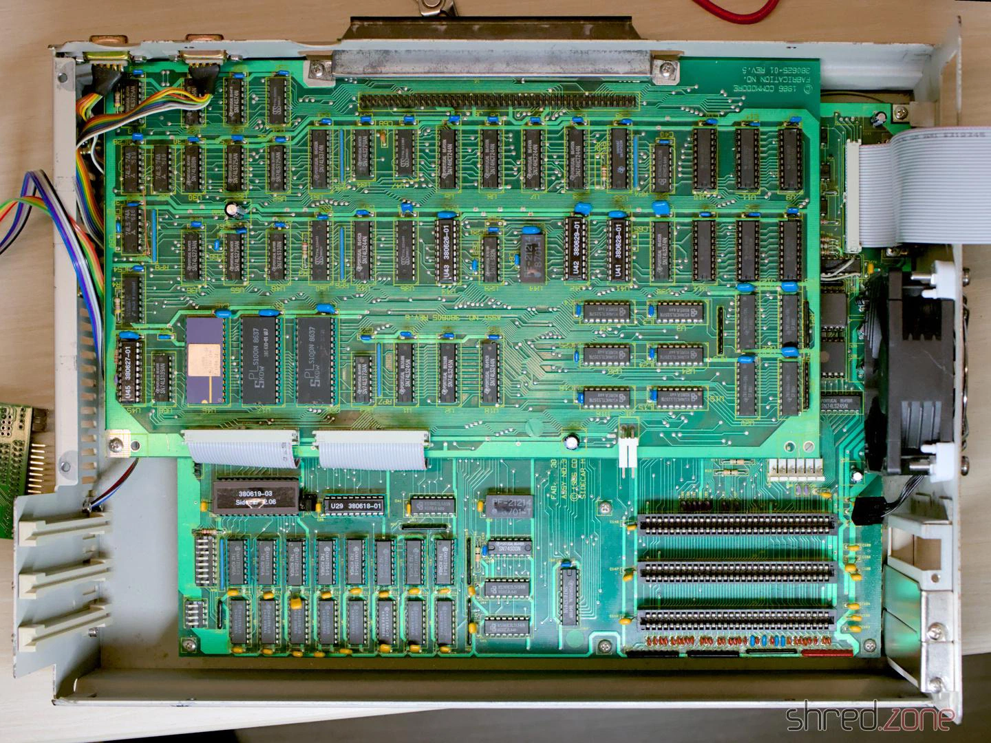
But I was on the right track! There is also a single PAL (and two FPLAs) on the lower board. I replaced this PAL as well, and also replaced the ribbon cables that are connecting both boards. The original cables still looked good, but the wires may have been damaged or corroded, and replacement is cheap.
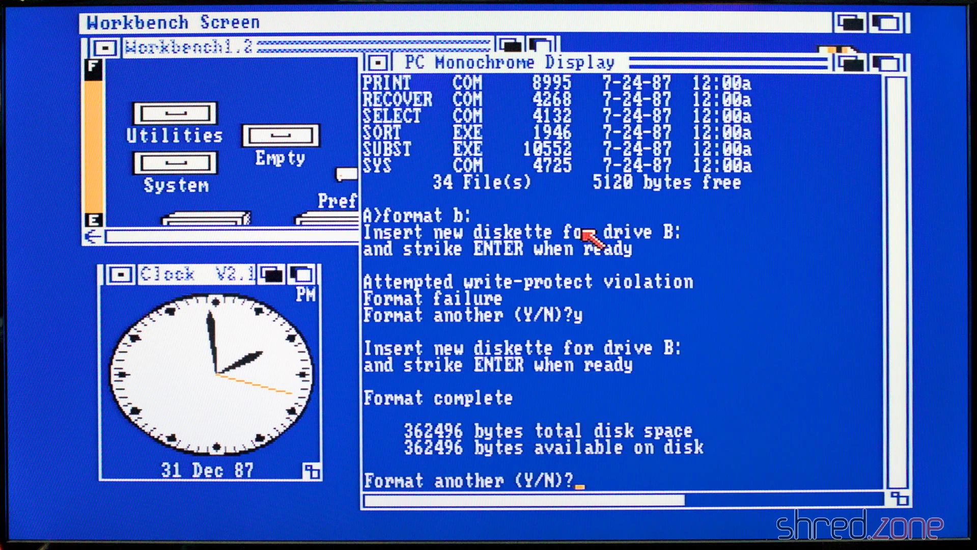
Next attempt. And finally, this time I was successful! I tested the machine for about an hour, formatted some floppy disks I bought somewhere, started Turbo Pascal. Everything worked reliably, and it was impressive to see MS-DOS running in one Amiga window and still have the full power of Amiga’s multitasking to run Amiga software.
I was lucky. The PALs were easy to replace, as compatible GALs are still being produced today. The FPLAs can also potentially lose their programming, but there are no modern replacements. Mattis Lind designed a replacement board that uses a modern CPLD, but there are no corresponding JED files for programming them.
And there it is, my fully restored and futureproofed Commmodore A1060 Sidecar!
The restoration was much more difficult than I expected. There were many bad surprises waiting for me, and more than once I was close to giving up the project and storing the Sidecar away for later.
This beast is difficult to repair. First of all because of its size. The Amiga 1000 plus Sidecar was too big for the table in my tiny workshop, so I could not use my scope. Also there is not much use in running the Sidecar alone, so you always need a running Amiga 1000 for troubleshooting. Third, it’s hard to find a place to put the Sidecar’s PSU while probing the boards. The open nature of the PSU also poses a risk of electrocution if accidentally touched. All in all it was an interesting experience and I have learned a lot about Commodore bridgeboards in general and the Sidecar in special, but I probably wouldn’t do it again.
Useful Links
In the first part, I disassembled the Sidecar. In this second part, I will fix all the broken things and put the Sidecar back together in its original state.
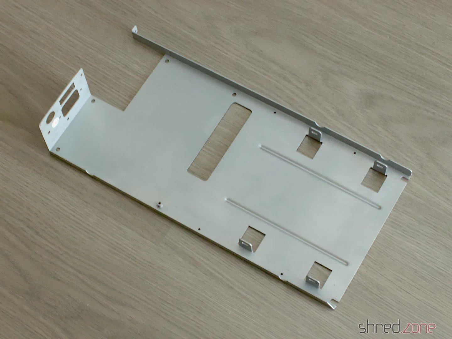
Let’s start with the mechanics. The floppy/PSU frame had some rust spots. I used a sanding machine to remove them all. Then I used zinc spray to protect the metal and restore the original look. The result was much better than expected. The frame now looks almost links new.
I got the overhauled PSU back. @DingensCGN, who already overhauled my Amiga 1000 PSU, did an excellent job again. He replaced all electrolytic capacitors and the power filter, removed the luster terminals and inserted a new pull relief. I also asked him to add a connector for a 12V fan. The original fan was a 230V model and was said to be awfully noisy. I never liked noisy computers, so I will replace it with a modern 80mm Noctua fan.
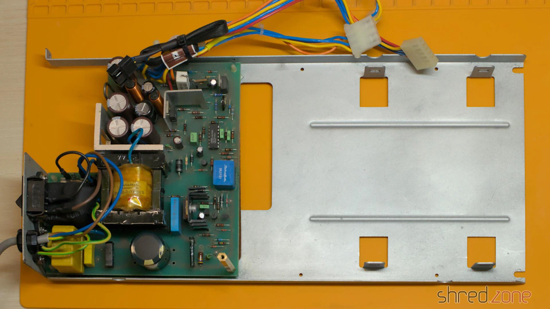
I’m always relieved to know that a power supply is safe to use, properly grounded, and won’t damage the machine or electrocute me. 🙂
I was also lucky enough to find a Chinon FZ-502 at an online auction. This type of floppy drive type was commonly used in a Sidecar and would restore the original look of the front.
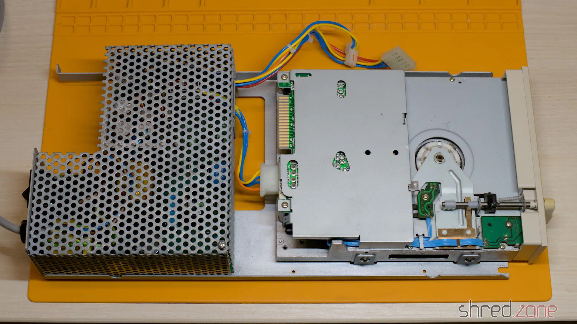
There is a metal shield supposed to be around the floppy drive, but unfortunately it was lost. It’s not a required part though, and no one would notice it was missing once the case is closed.
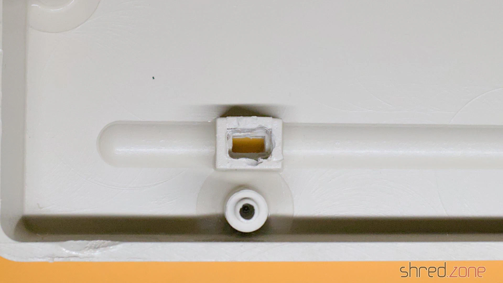
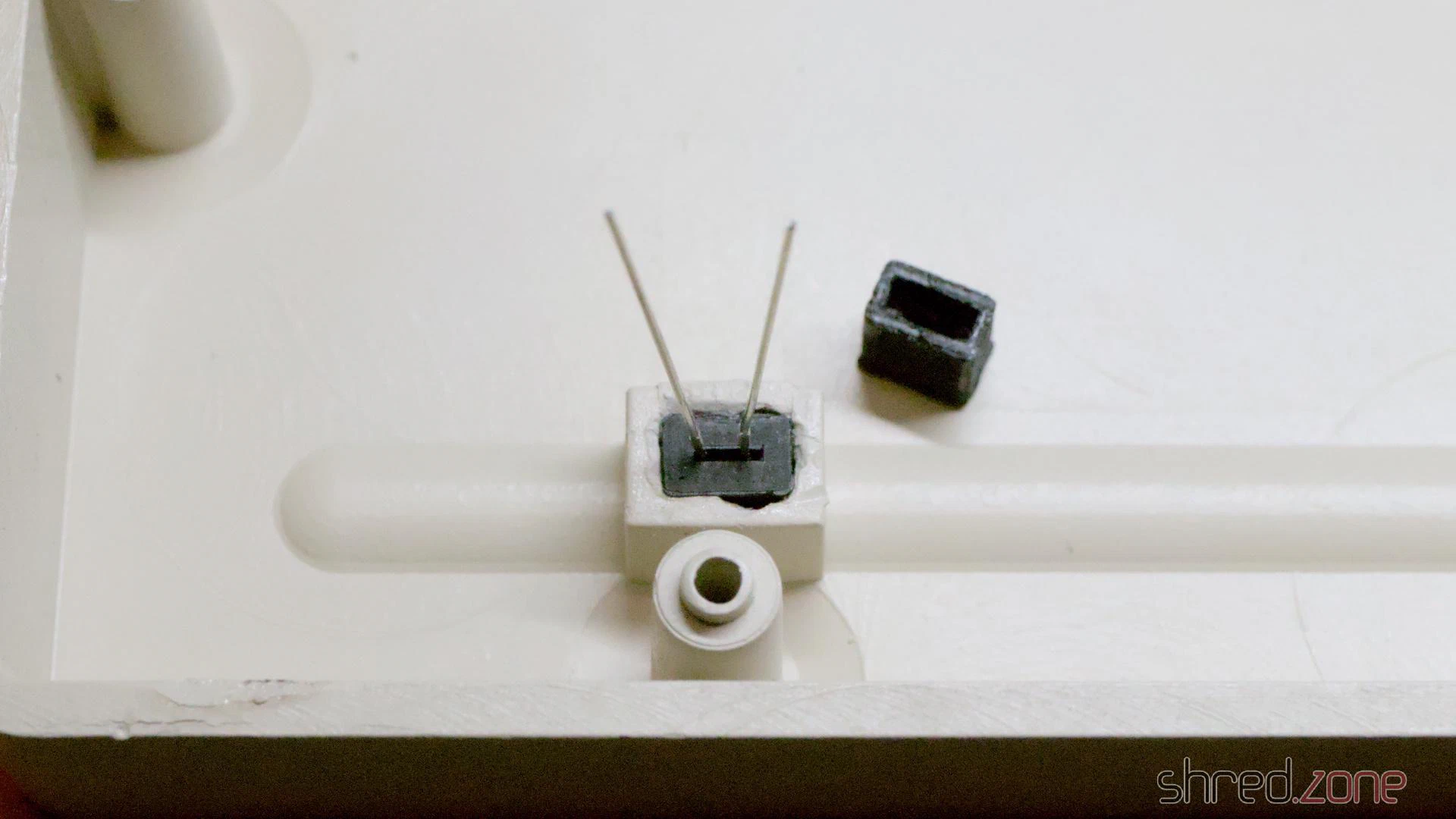
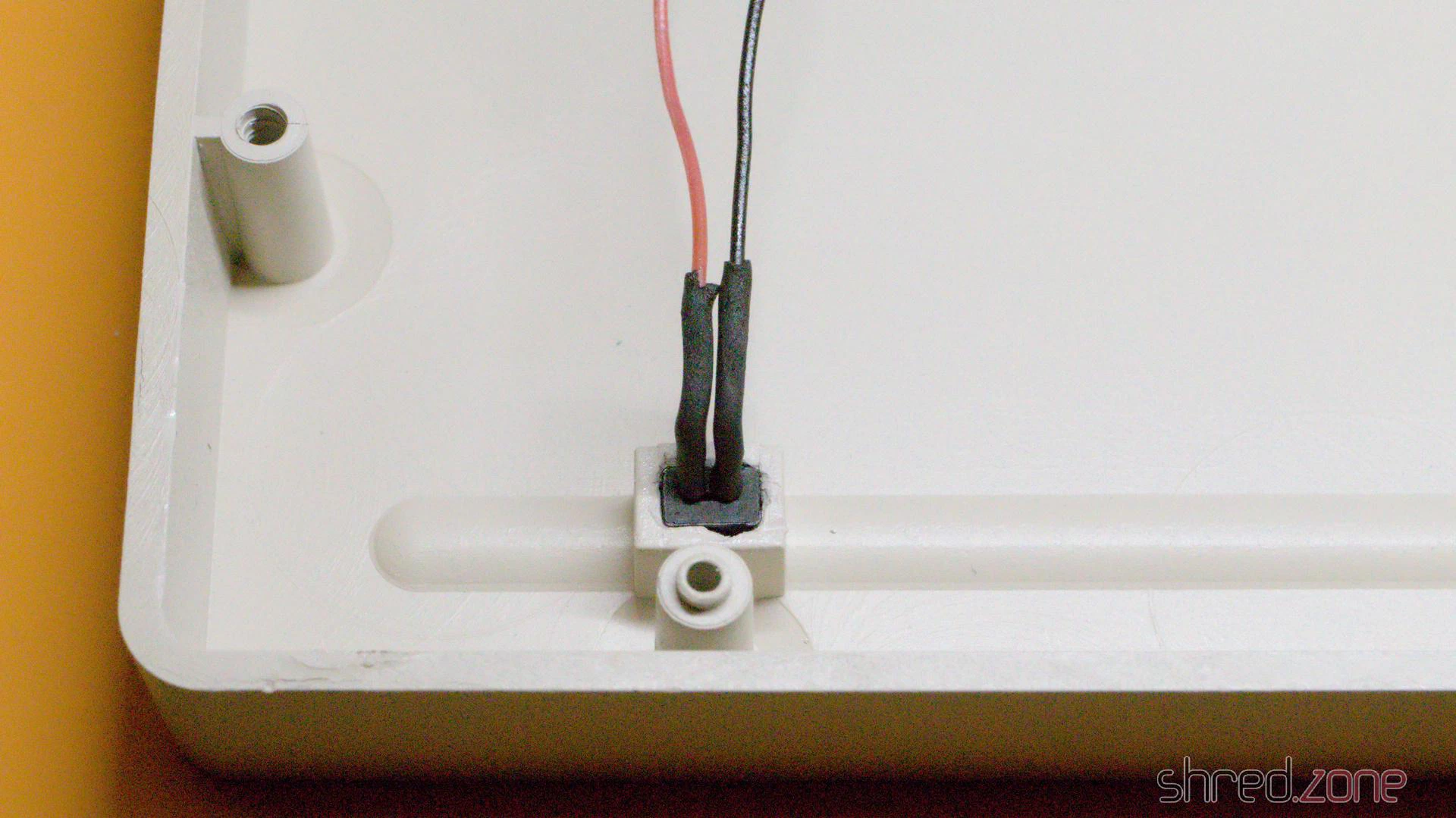
Next problem: The legs of the power LED were broken off and the LED is stuck. I had no choice but to use brute force. I drilled out the LED and the plug that held it in place. I had to be very careful. If I drilled too deep, I would ruin the look of the front.
I then used a new standard rectangular red LED and 3D printed a plug to hold it in place without glue. The new LED is held firmly in place, but could still be removed by gently pushing it out from the front side with a screwdriver.
The mechanical part is done. Time for the electronics.
On the upper board only a single electrolytic cap had to be replaced. But it took a lot of unsoldering work to remove the broken Zorro connector and the six bus driver chips. The original Zorro connector was held in place by two rivets, and I had no choice but to drill them out, slightly damaging the board in the process. I then washed the board thoroughly with IPA.
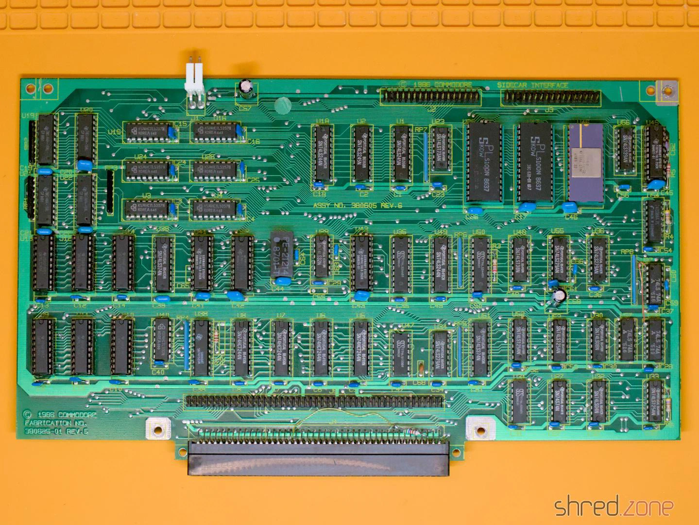
There was also a tantalum capacitor, which I replaced with a new electrolytic one. This is not really necessary, but I don’t trust old tantalums. They cannot leak like electrolytic ones, but they can catch fire or explode, causing even more damage to the board than electrolyte.
On the bottom board, there were ten electrolytic caps due for replacement. I also replaced the rusted piezo buzzer, which was a bit difficult because the new one turned out to be surprisingly sensitive to heat.
I don’t like empty sockets, so I organized an 8087 FPU. Eight 41256 DRAM cells will upgrade the machine to the maximum possible 512 KB RAM. (The famous 640 KB can only be reached with a RAM expansion card.)
The installed Sidecar V2.06 firmware was the latest version I could find, so I just gave the original EPROM a new label, as the old one came off because the glue had dried out.
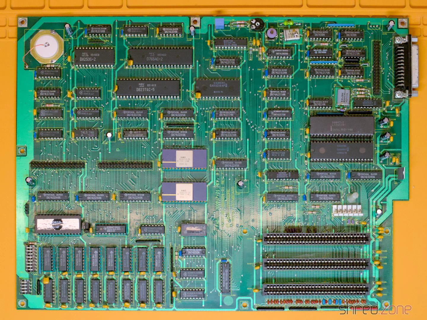
The board needs a new configuration after the change. Fortunately the original manual can still be found.
I also replaced all screws with new ones.
And finally, it’s time for reassembly. Probably for the first time in decades, the Sidecar’s case was closed again.
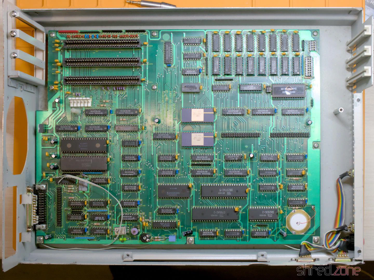
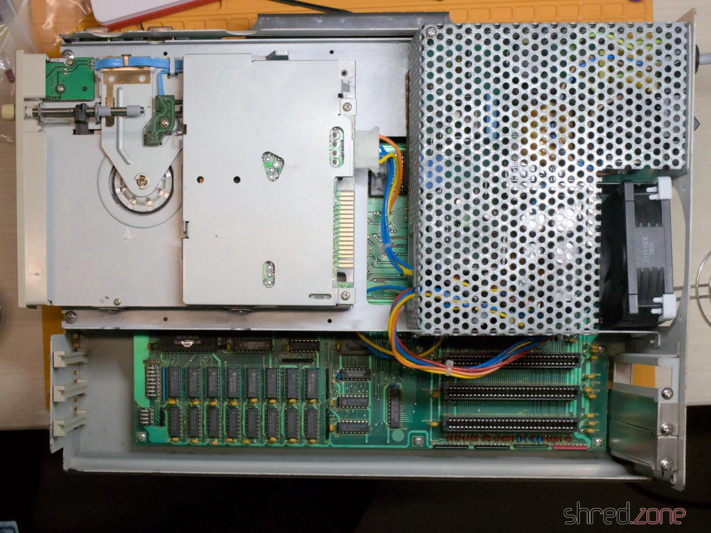
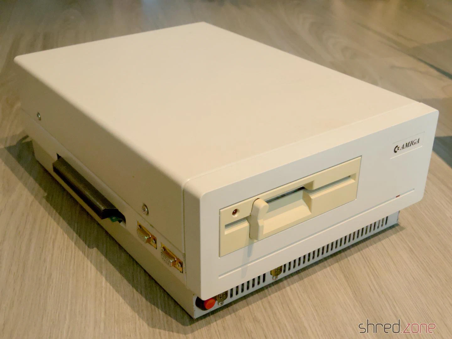
Isn’t she a beauty? 😍
That’s all for the second part. If you’ve been following my article closely, you’ll have noticed that I haven’t turned on the machine yet. That’s right. I avoid powering up old computers without at least having the PSU inspected, because there is a risk that (after decades of storage) the PSU is defective and could damage the machine or go up in smoke.
In the third and last part I will connect the Sidecar to my Amiga and finally find out if it works.
List of Capacitors
Lower board:
- 2x 100µF 16V radial
- 8x 47µF 25V radial
Upper board:
- 1x 100µF 16V radial
- 1x 47µF 25V radial (as replacement for the tantalum at C57)
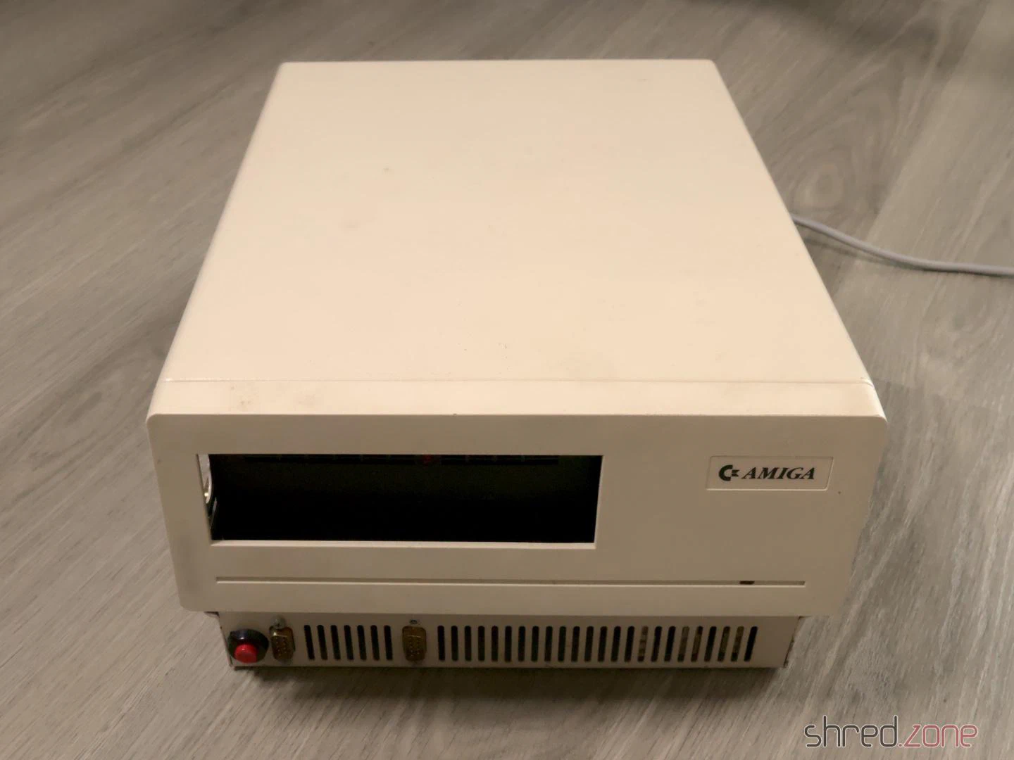
But what is a Sidecar? When Commodore released the Amiga 1000, its graphics and sound capabilities were unmatched in that price range. However, because the machine was based on the Motorola 68000 processor, users were unable to run existing MS-DOS software on the machine.
The German Commodore factory in Braunschweig tried to solve this problem with the Amiga 1060. The machine was connected to the Amiga 1000 and provided a full IBM compatible PC. Although it was a standalone computer, it had no video and keyboard ports, but was fully controlled by the Amiga. Because it was connected to the right side of the Amiga, it looked like the sidecar of a motorcycle, which gave it its nickname.
The Sidecar came relatively late to the market, could only be used with the Amiga 1000, and was quite expensive. For this reason, only a small number were produced. I could not find any official figures, but according to Dr. Peter Kittel (an engineer at Commodore Braunschweig) only between 3,000 and 5,000 units were sold in Germany, and certainly even less worldwide.
My A1060 came with an open case top. The reason was that the 5¼" floppy drive had been removed, and a full-height hard disk drive had taken its place. It was so tall that it didn’t fit in the case, and it was also surprisingly heavy.
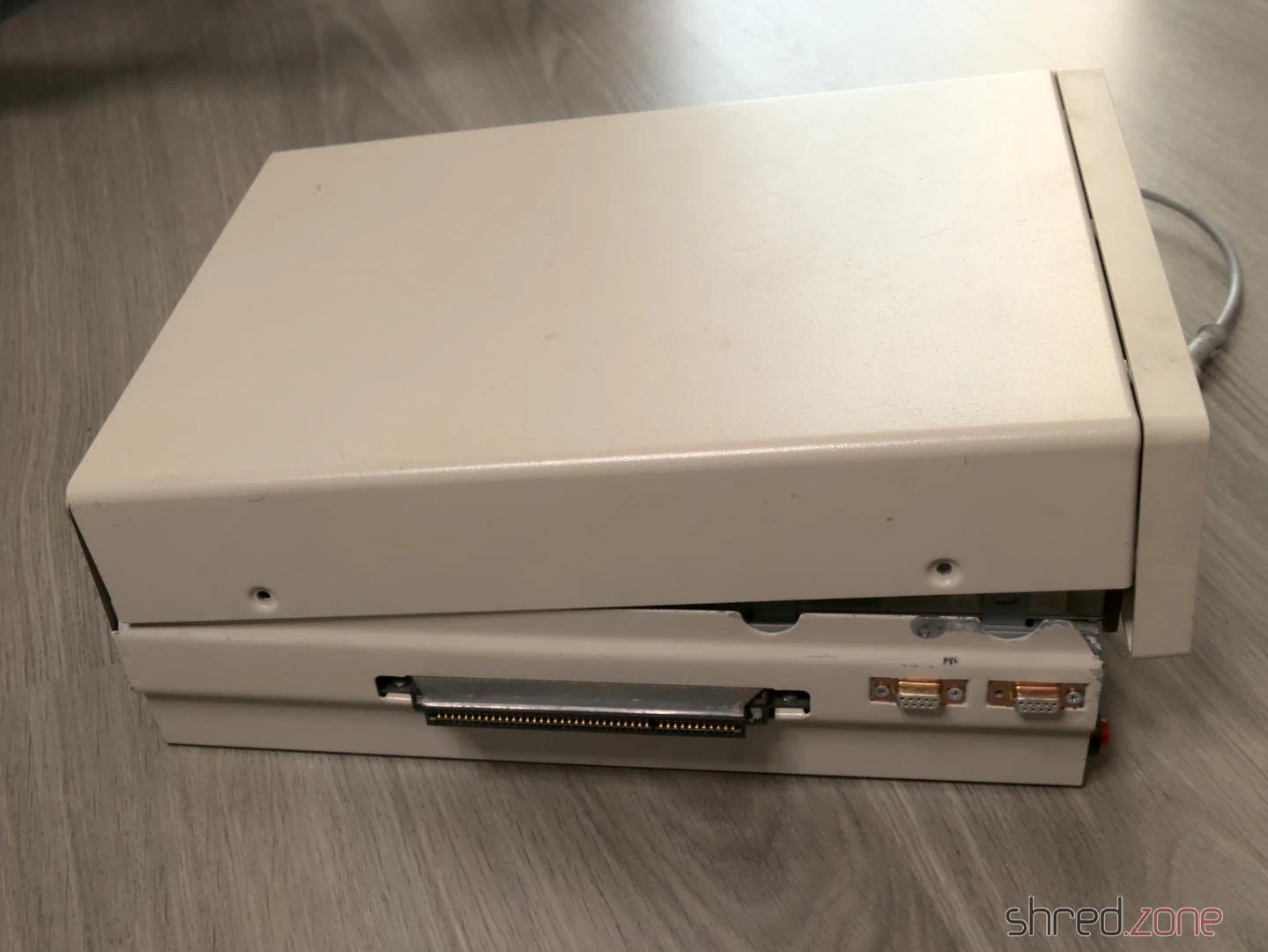
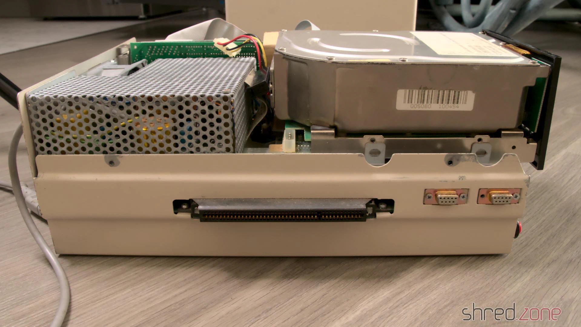
Many screws were missing or oxidized, but otherwise the machine was in used but acceptable optical condition. The previous owner had added a reset button on the front, and a second D-Sub connector on the back (which later turned out to be a second floppy drive connector, for whatever reason).
I decided to take the entire machine apart for cleaning and damage assessment. My plans are to restore it to its original state, which also means removing the oversize hard drive and its controller board.
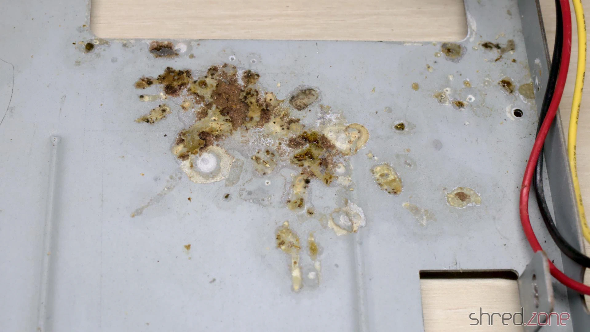
There is a frame that holds the floppy drive and PSU. I found a lot of strange rust on it, which looks a bit like moisture damage, but that wouldn’t explain the shape of the stains.
The PSU looked okay-ish. Luster terminals were used for the floppy power connector. Also the pull relief for the Amiga power cord was missing, instead I found a knot in the cord.
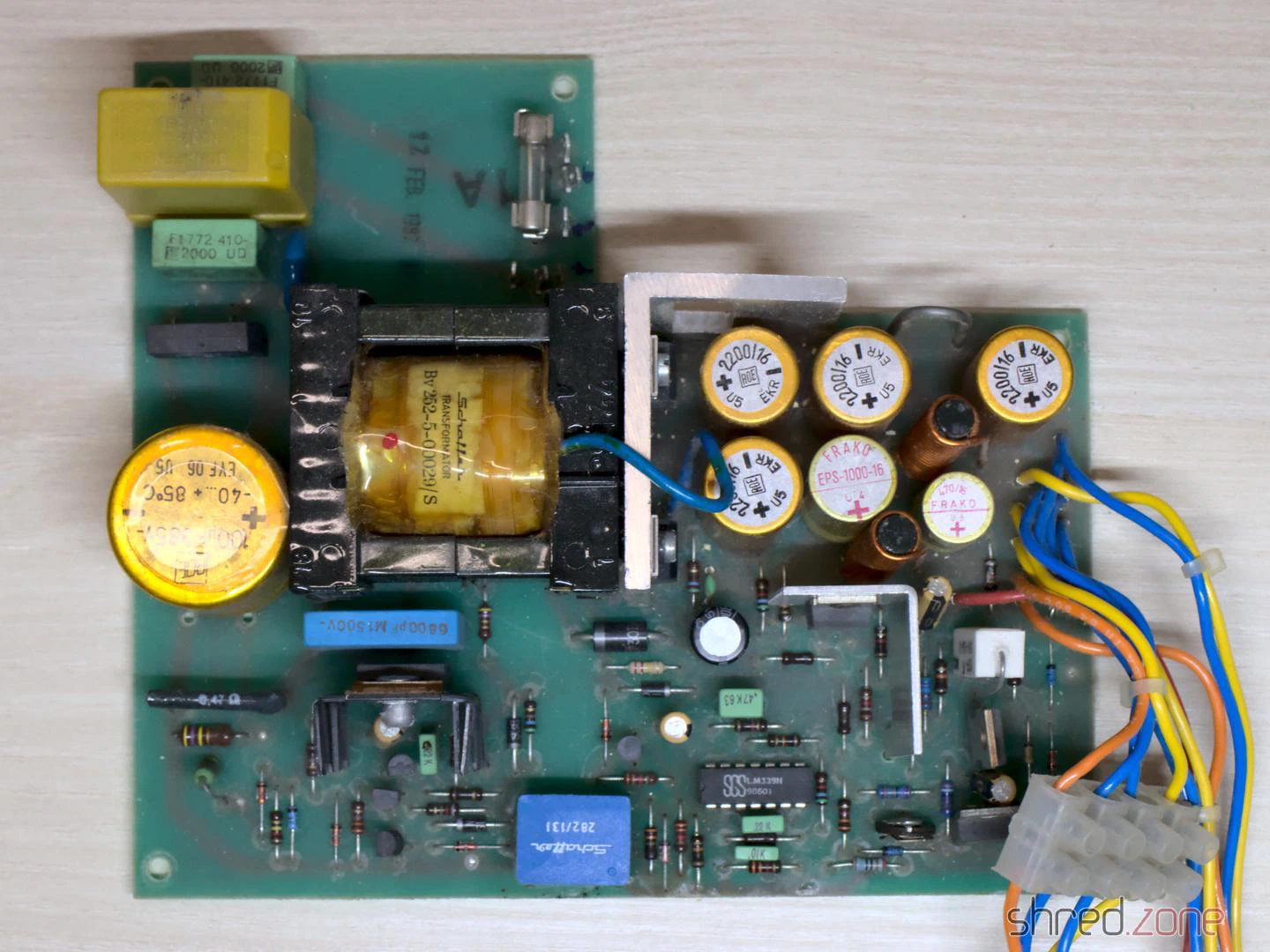

I gave the PSU to an experienced technician at the a1k.org Amiga board for overhaul.
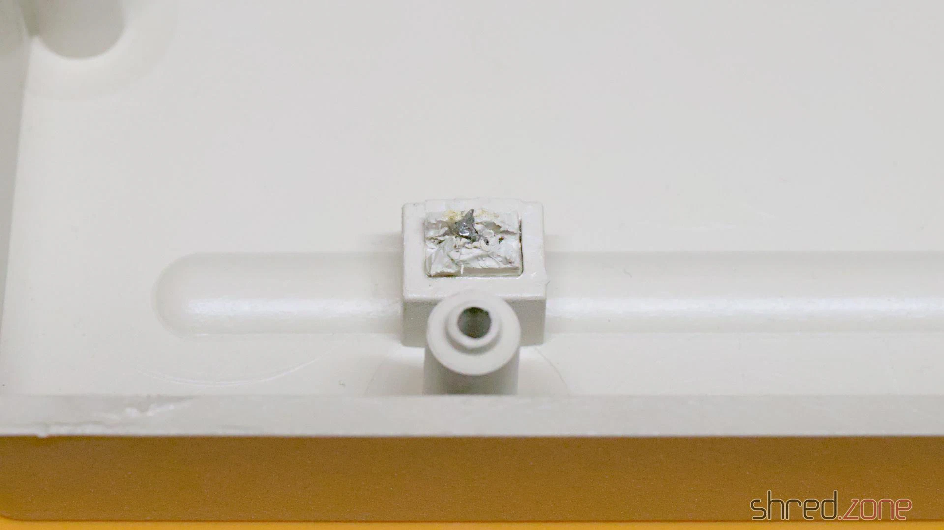
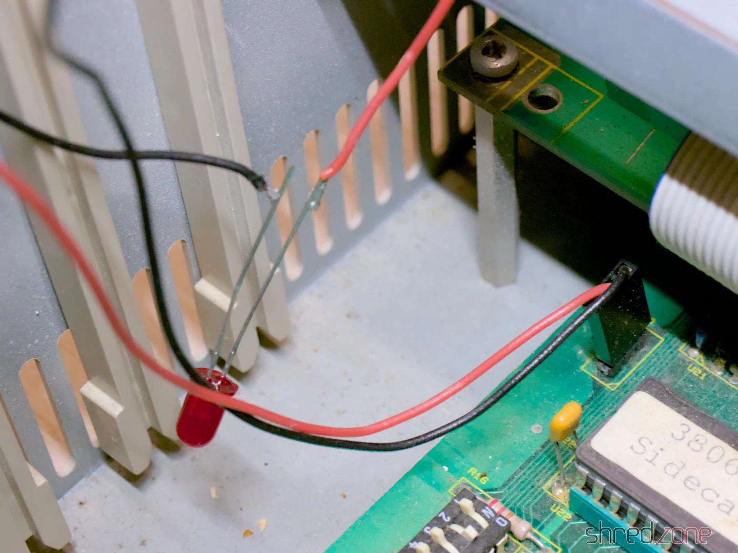
I also found that the pins of the power LED were broken off. The LED was held in place by a superglued plastic plug. It was impossible to remove without force. The replacement power LED was just hanging loosely in the case.
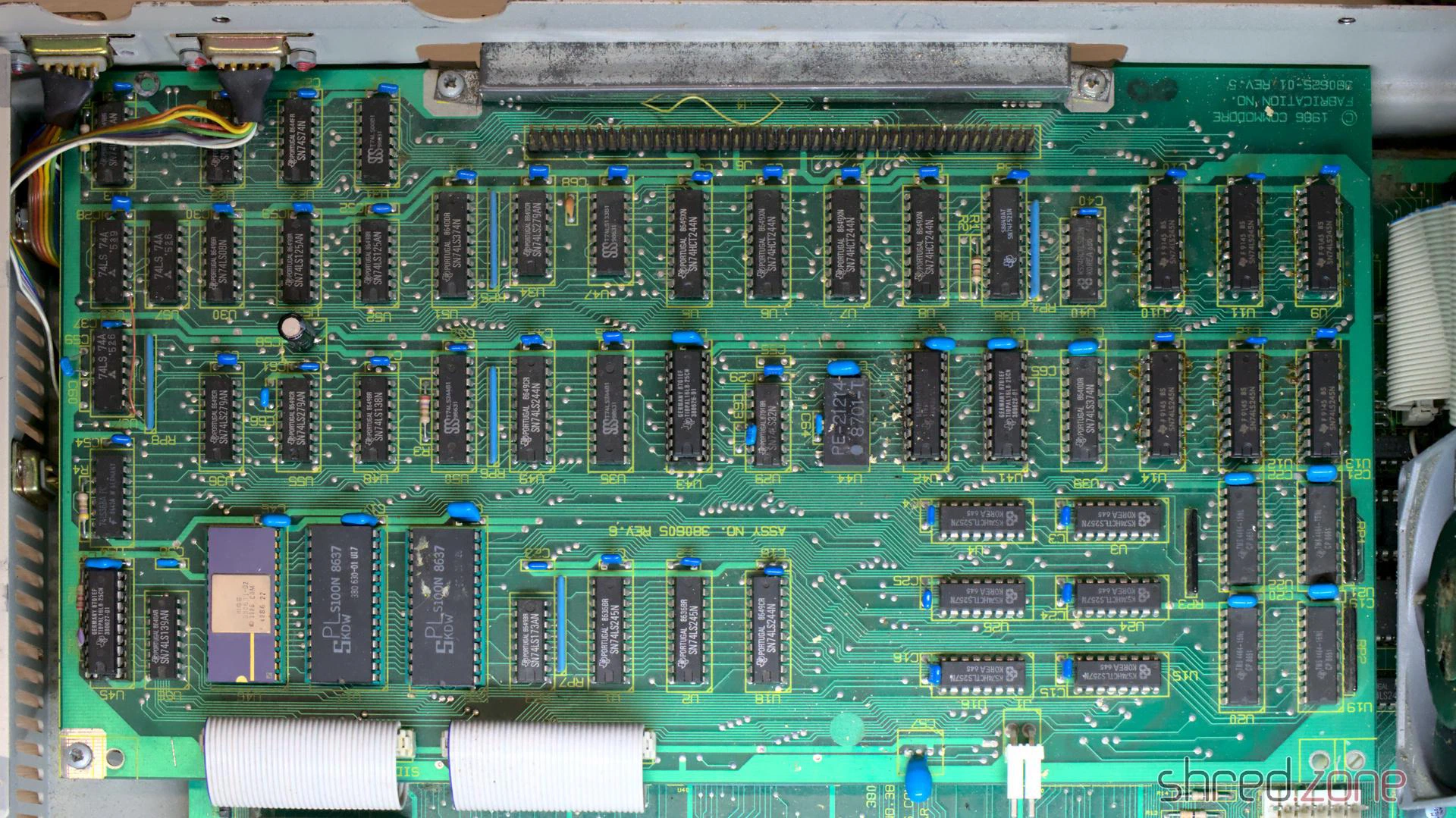
Let’s dig deeper. The computer consists of two boards. The lower board is the PC compatible, with three XT bus slots, a socket for the FPU, and eight sockets for another 256 KB of RAM. The upper board serves as a bridge between the Amiga and PC side. Both boards are connected by two flat ribbon cables.
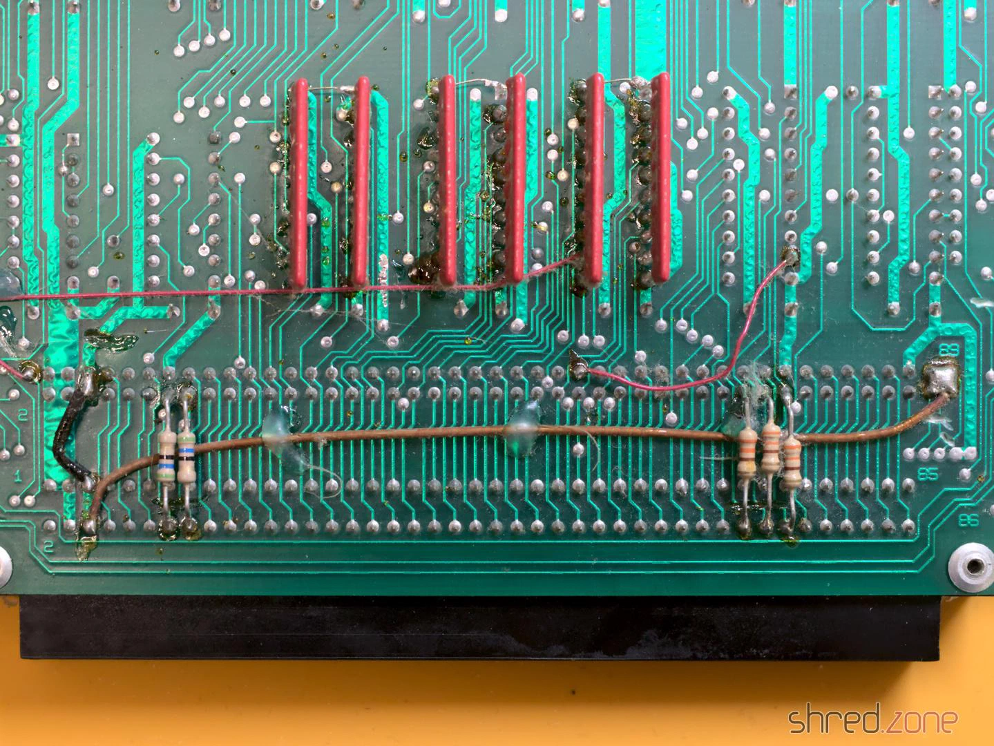
At the first glance, the upper board looked dirty, but otherwise okay. On the bottom side there are a lot of bodge wires, additional resistors, and cut traces. At first I thought that this modification had been done by the previous owner, but then I found similar photos on the internet, so it seems to be a standard post-production factory fix.
Then I found that six 74HC245 bus drivers had been replaced with 74LS245 ones. The replacement was a little “creative”. The old chips were cut off the board leg by leg, and the new chips were then soldered to the remains of the old legs. This was certainly not factory-made.
On the one hand, I was glad that the previous owner did not try to unsolder the chips, as he could have damaged the board. On the other hand, it looked very DIY, so I decided to clean up the mess later.
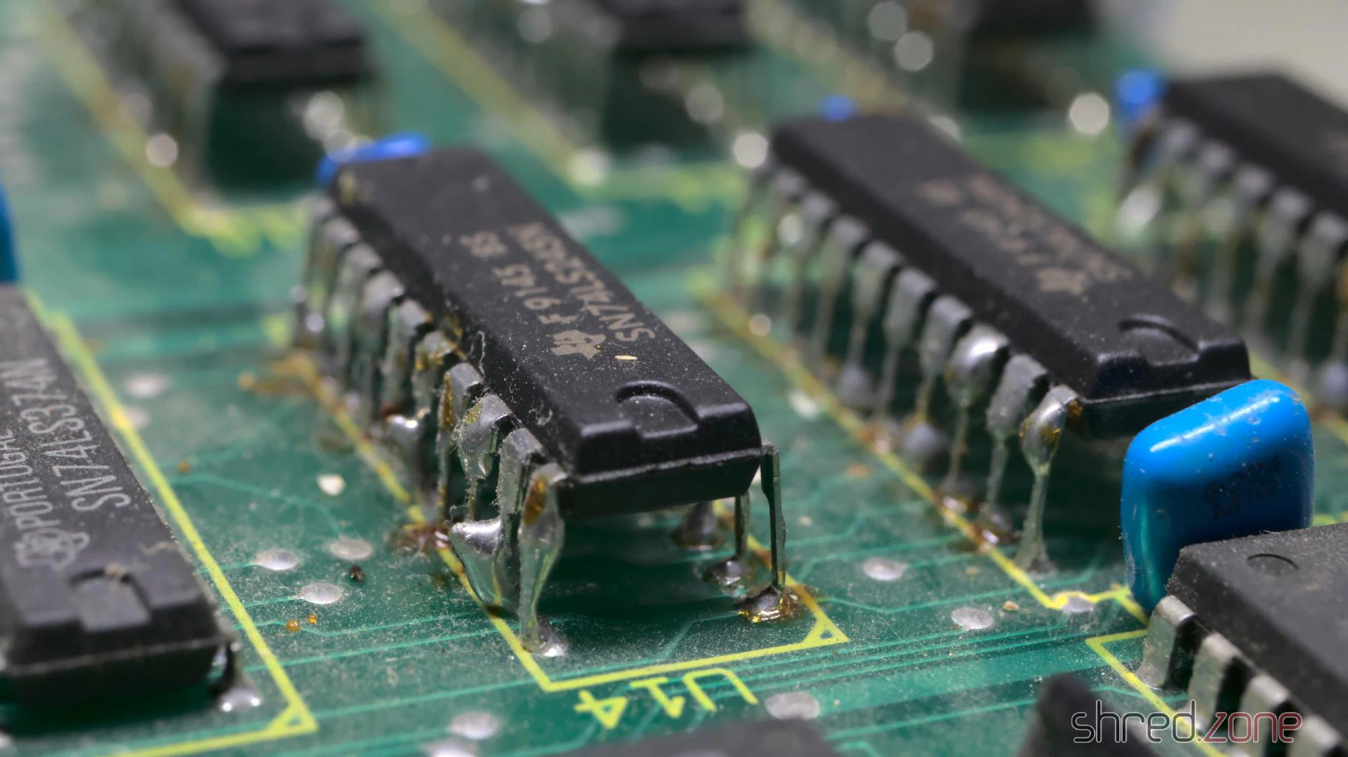
Replacing the 74HC245 with 74LS245 turned out to be a common fix to make the Sidecar more compatible with Amiga memory expansions. I decided to keep the 74LS245, but to use sockets so that it would be easy to undo this modification.
I also found that the Zorro connector was unfortunately damaged beyond repair. Two pins were broken off and another one was bent so it could cause a short.
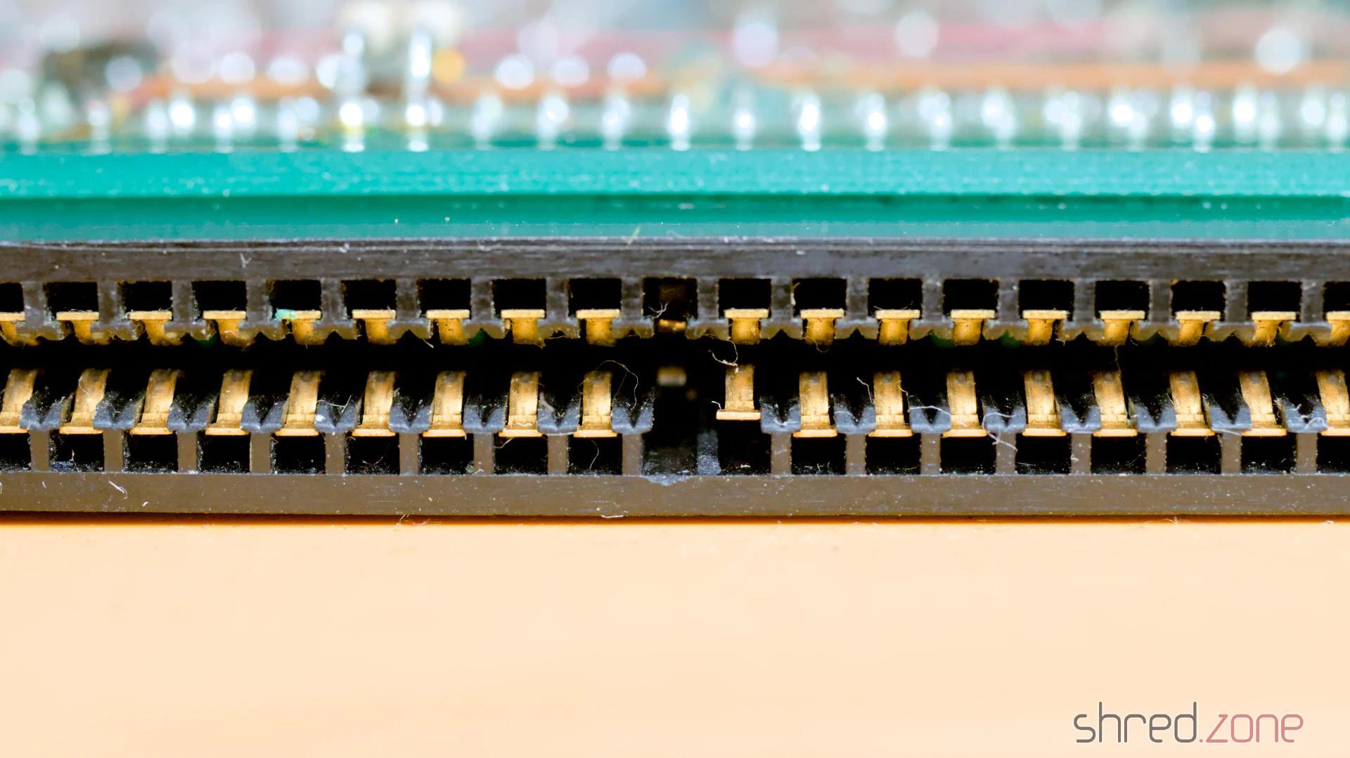
It was impossible to find a replacement 88-pin edge connector that could also be riveted to the board, but I did find a new connector of the correct size but without the rivet holes.
The lower board was even dirtier, but otherwise seemed to be unmodified and undamaged. The buzzer, however, was rusted, so I would have to replace it.
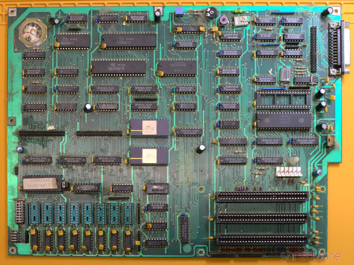
In the end, there is a lot of work to be done:
- Clean the case, remove the rust, replace all screws
- Fix the power LED
- PSU overhaul
- Replacing all electrolytic caps, the buzzer, and the Zorro connector
- Clean up the six bus drivers at the upper PCB
- Find a new floppy drive
More of this in the second part of this article!
In the first part, I repaired the motherboard of an Amiga CD³² that was damaged by leaking capacitors and a botched restoration attempt. In this part, I am now replacing the laser unit and calibrating the CD drive.
The old laser unit in most CD³²s is likely worn out due to age and use. A common symptom is that the CD³² no longer plays CD-R media or only recognises music CDs. Incidentally, the CD³² generally does not recognise CD-RW media, as these use a dye instead of pits, which reflects too little light. This cannot be fixed even with a new laser unit.
Before we start, a heads-up:
WARNING: The laser unit is very sensitive to electrostatic discharge. Always take protective measures, e.g. by wearing an antistatic wrist strap.
Ensure that the laser is always covered when the computer is switched on (e.g. with a CD or a piece of paper). Do not look into the laser beam.
I would also like to mention at this point that I am not a trained technician. I have read guides on calibrating CD drives, and it worked for me. However, I do not claim that this is the best or most professional way to perform a calibration.
To replace the pick-up, a soldering iron and definitely an oscilloscope for the subsequent calibration are required. It might be possible without calibration, but the result will not be optimal.
Replacing the laser unit
First, I removed the CD drive from the case. Then I carefully separated the mechanical unit from the controller, and removed the four screws holding the frame of the mechanical unit. The metal shielding covering the pick-up must also be removed.
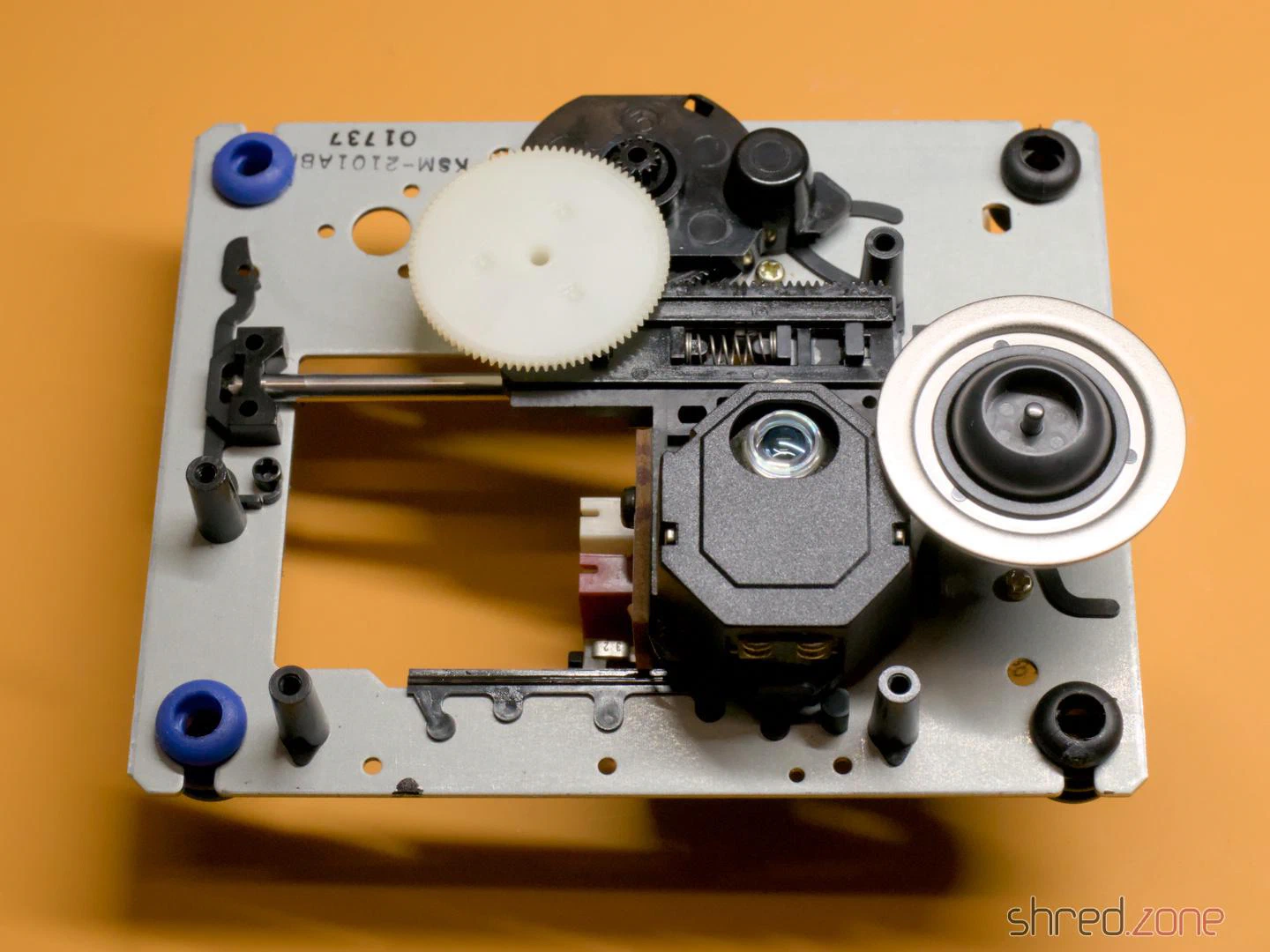
The pick-up is a Sony KSS210A. It is out of production for a long time, but replicas are offered on online marketplaces for a few euros. To remove the old unit, I first took off the white cog and then pulled out the metal rod (it is only held by a plastic clip that can be pushed to the side). While I was at it, I removed the old grease from the rod and the cogs, and then applied a little silicone grease. After that, I mounted the new unit and reassembled the CD drive in reverse order.
Important: Immediately after the new laser unit is connected to the controller, a solder blob on the laser unit must be removed! It protects the laser from static electricity, but would irreparably damage the drive controller if it is still present when switched on.
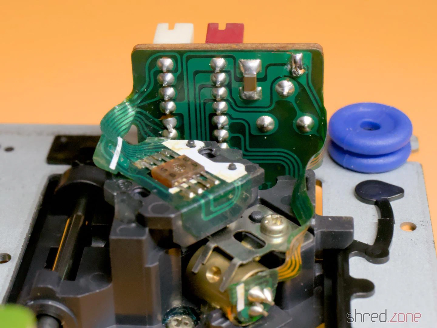
If you want to keep the original laser module, you should also apply a solder blob there before disconnecting it.
Preparation
I removed the metal shielding of the drive controller to perform the calibration. There I found a surprise: a tiny circuit board glued to the motherboard and connected with seven wires.
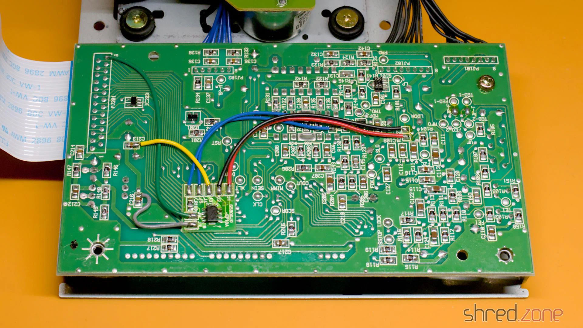
At first I assumed this might be a mod to bypass copy protection measures. However, the CD³² didn’t have a sophisticated copy protection system to bypass. Later I found the answer in a YouTube video: This modification cuts the power supply to the laser and the spindle motor as soon as the lid of the CD drive is opened. However, I could also find many photos of the controller board without the modification. I assume it was a product safety requirement so the CD³² could be sold on the German or European market.
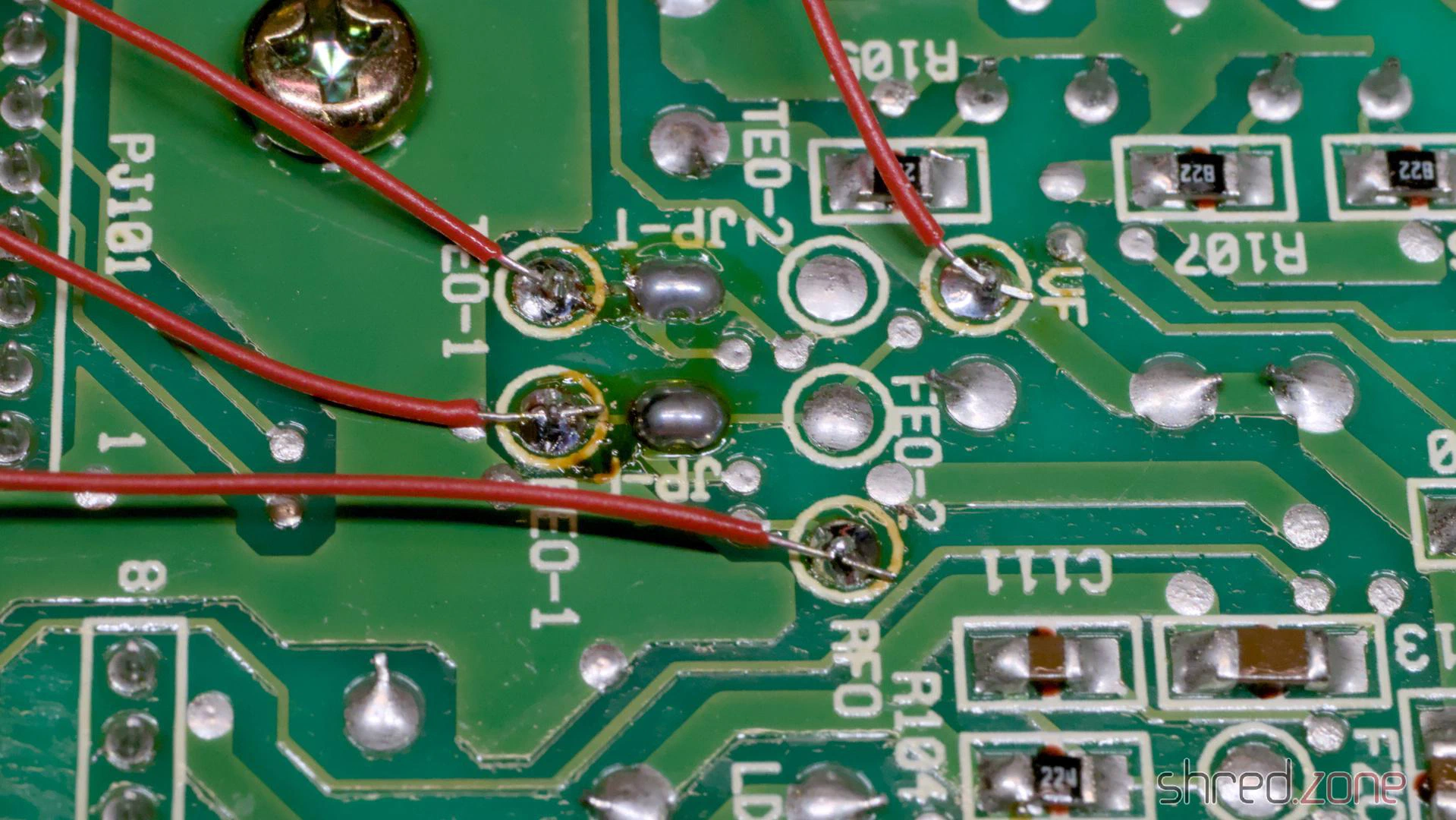
Okay, back to the calibration. As a preparation, I soldered wires to the test points VF, RFO, TEO-1 and FEO-1. I recommend using different colours for this, it makes the calibration easier. Unfortunately, I only had red wire at hand, so I had to check every time which wire went where.
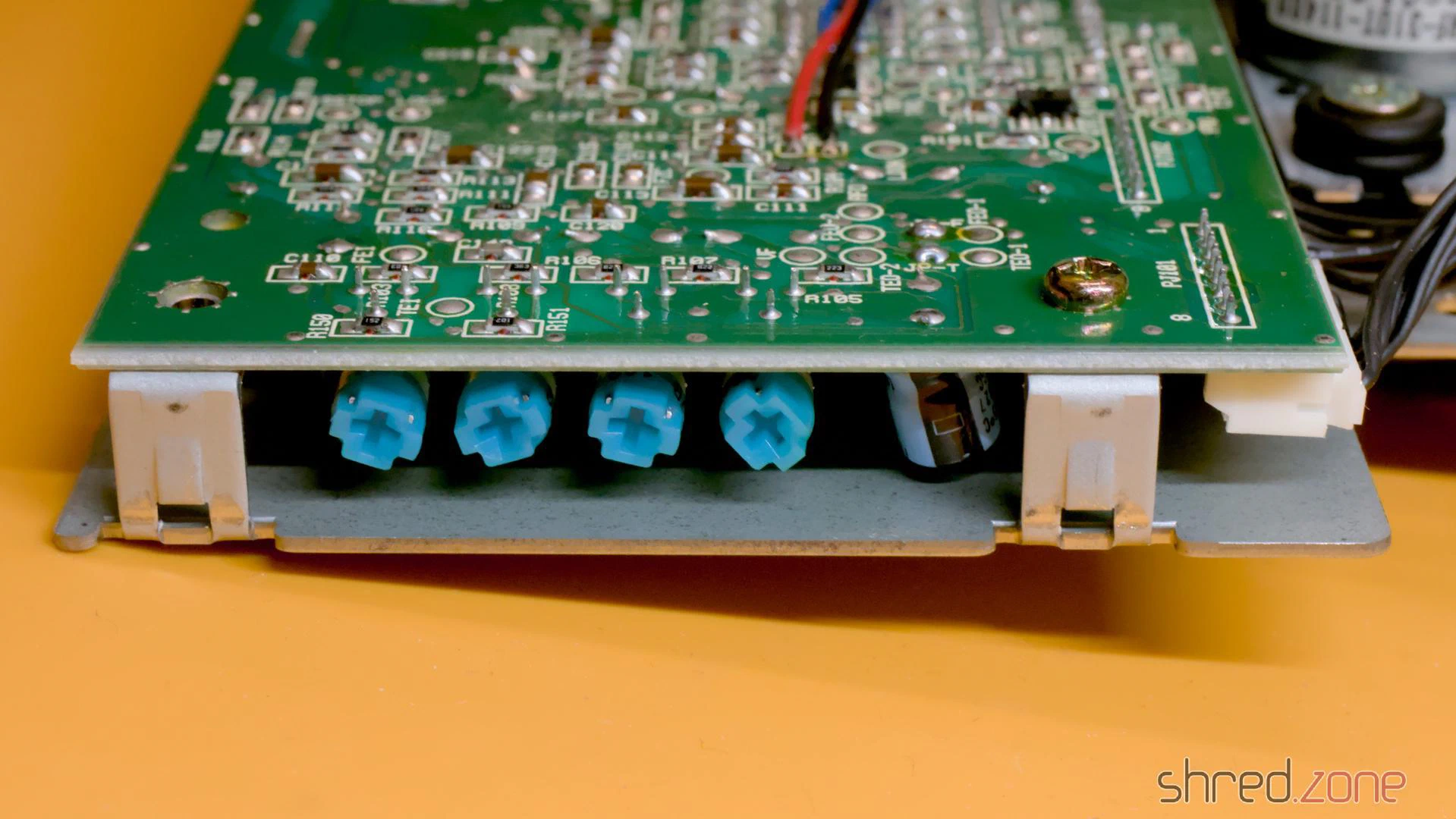
After that, I measured the current settings of the four potentiometers on the controller board and the potentiometer on the laser module with an ohmmeter, and wrote them down. If the calibration should go wrong for any reason, I could restore these settings at any time. A photo of the potentiometer positions would be far too inaccurate, by the way, better to measure!
For the calibration, the drive must be reconnected to the motherboard. The top of the case (with the LEDs, the reset button, etc.) must also be connected, as the CD³² does nothing as long as the drive lid is open. The laser unit moves during operation and should have enough space for this.
To hold the CD on the spindle, I removed the spindle clamp from the inside of the lid and fixed the loose part in the middle with a little sticky tape. A magnet holds the clamp to the spindle and ensures that the CD does not slip.
Calibration
The actual calibration process is explained in this blog article by TSB. My attempts to explain it would be far worse. 😉
It turned out with my drive that the process didn’t work like that. After I had carried out the first steps of the calibration, the drive suddenly went on strike and didn’t read anything at all. Fortunately, I had noted down the potentiometer positions, so I could restore the original settings and start over.
Afterwards, I first calibrated the TEB pot until there were about 0 mV between TEO-1 and VF. The drive was still running after that. Only when I calibrated FEB as documented did it strike again. I undid this change and continued with the calibration of the laser power.
WARNING: Be extremely careful with the potentiometer on the laser module and only turn it in very small steps. Otherwise, the laser can be permanently damaged.
There may be a drop of varnish on the pot. It is advisable to turn the pot first while it is switched off to break the varnish, and then use the ohmmeter to reset it to the noted factory setting.
To calibrate the laser power, I connected the oscilloscope to RFO and ground. Then I put a music CD on the spindle and started track 1. The oscilloscope should now show a so-called “eye pattern”:
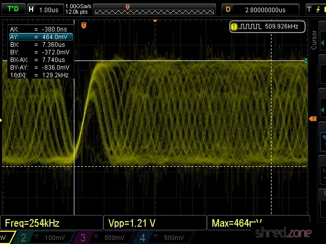
The tricky part is to adjust the pot on the laser module while the CD is playing. I adjusted it very carefully until I reached a peak-to-peak voltage of about 900 mV. 1200 mV should never be exceeded.
Then I adjusted the FEB pot on the controller board until I reached a maximum amplitude in the eye pattern.
The last two pots, FEG and TEG, are calibrated by measuring the test points FEO-1 and TEO-1 respectively against ground. The drive should be playing track 1 of an audio CD and be in pause mode during calibration.
I tried to find the ideal point where the signal on the oscilloscope is as smooth as possible and the correction noises of the laser optics are as quiet as possible. The goal is to find the best possible compromise. You will probably get the best results if you listen to the noises of the laser unit and follow your gut feeling.
The calibration is then complete and the CD³² can be reassembled.
Tip: Burn CD-Rs for the CD³² at the lowest speed your burner supports. This increases the contrast of the data on the CD. Also, prefer CD-Rs that are not transparent when held up to the light.
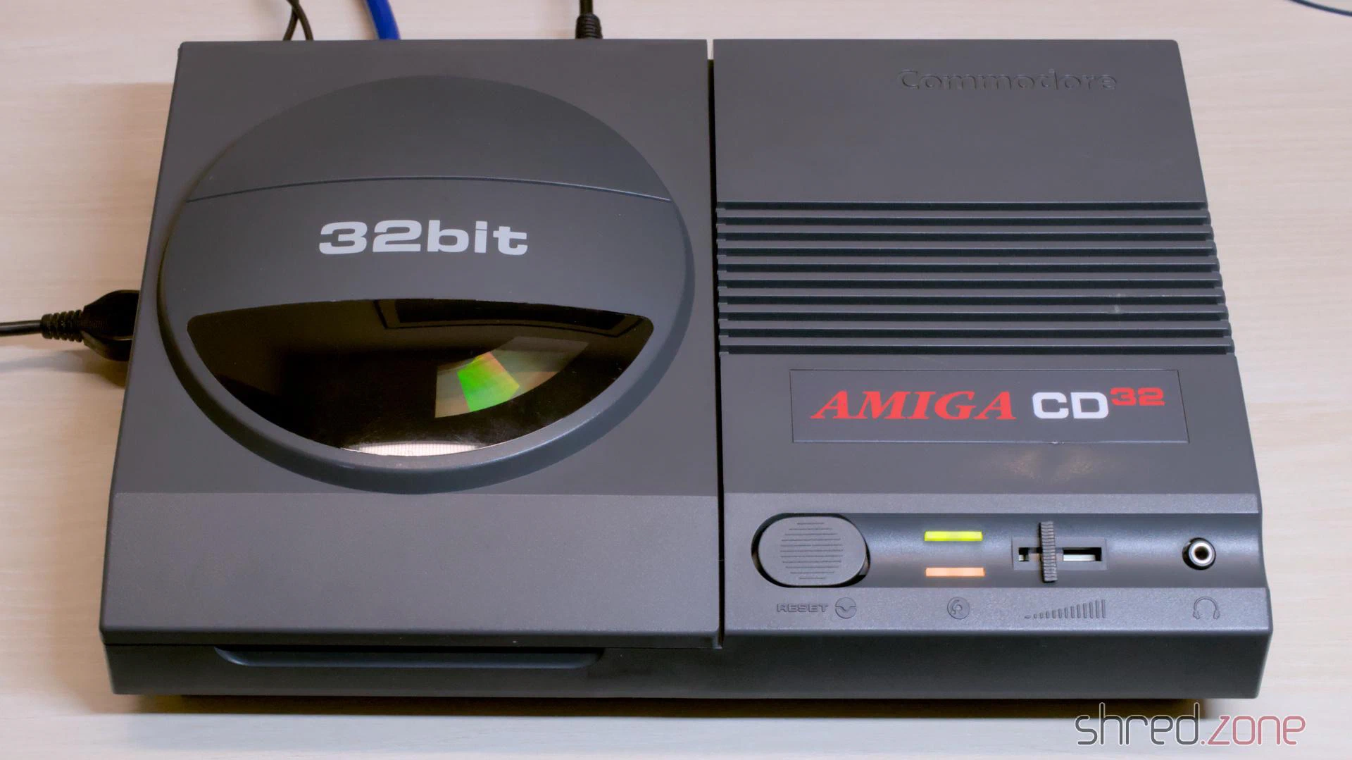
I found this CD³² at a fair price. The machine is still missing from my collection, so I grabbed it. The visual condition of the casing is quite good. There are a few visible scratches. The previous owner tried to touch them up, but only made it worse. At the time, I didn’t suspect that this would be the main theme of the entire restoration.
Together with the games console, I received a power supply and a maths edutainment CD. The power supply wasn’t original, but rather a typical “brick” for external hard drives with a soldered-on CD³² plug. Unfortunately, the gamepad was missing, but luckily I found a practically mint condition Honey Bee Joypad as a replacement a bit later.
Let’s take a look inside.
The Condition
The Amiga was sold as defective because it didn’t display a picture.
The circuit board told me a completely different story. An attempt had already been made to replace the capacitors. After replacing the TH and 100µF SMD capacitors, the attempt was abandoned. Presumably because the picture was gone after that.
I also found several green varnish spots, probably simple nail varnish. It was underneath the replaced SMD capacitors, on solder joints as well as some vias. The varnish made cosmetic sense at best in those places.
And then I found this:
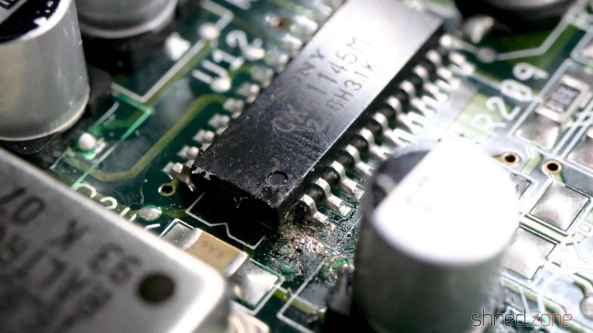
I can only speculate at this point: When the picture suddenly disappeared in the middle of recapping, the previous owner assumed that the video encoder chip was damaged. An SMD chip can only be removed with a hot air rework station, which they probably didn’t have available. So instead they tried to cut the chip off the board leg by leg. Fortunately, they aborted the attempt after just one leg.
Luckily, I didn’t find any further traces of “abuse” on the poor board. It will be enough work as it is to clean up the existing mess.
To be honest, I’m quite annoyed about it. It makes a difference whether the machine simply stops displaying a picture after decades in the cellar, or because someone botched around on the circuit board. The seller should have pointed this out, naturally with corresponding negative effects on the price.
Repair of the Mainboard
At this point it made the most sense for me to restore the picture first. So I replaced the video encoder, as well as an already replaced electrolytic capacitor right next to it that looked suspicious. With that, all visible defects were eliminated. Unfortunately, it didn’t bring the video signal back.
Why did the picture stay black? Were there other faults in the video section, or did the machine possibly not boot up at all?
To find out, I inserted a DiagROM and connected the CD³² to my PC. The DiagROM booted without any problems and logged no errors on the console. Good news: The problem had to lie solely in the video section.
So it was time to tidy up. I removed all electrolytic capacitors, including the ones that had already been replaced. After that, the green nail varnish came off, with nail varnish remover and isopropanol.
On the underside I found a strange solder lump covered by a thick layer of varnish. When I tried to remove it, a telltale fishy smell of leaked electrolyte wafted up. Not a good sign. It meant that a capacitor had leaked and the area wasn’t properly cleaned. I generously removed the SMD parts on both sides in this area, cleaned the board thoroughly and checked the tracks and vias.
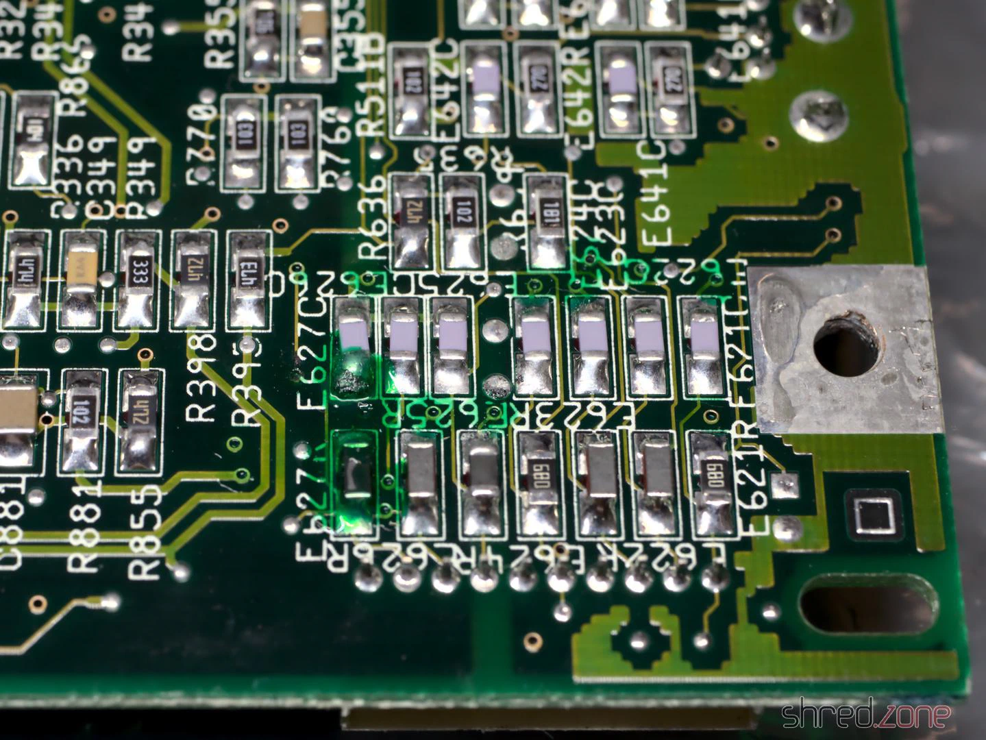
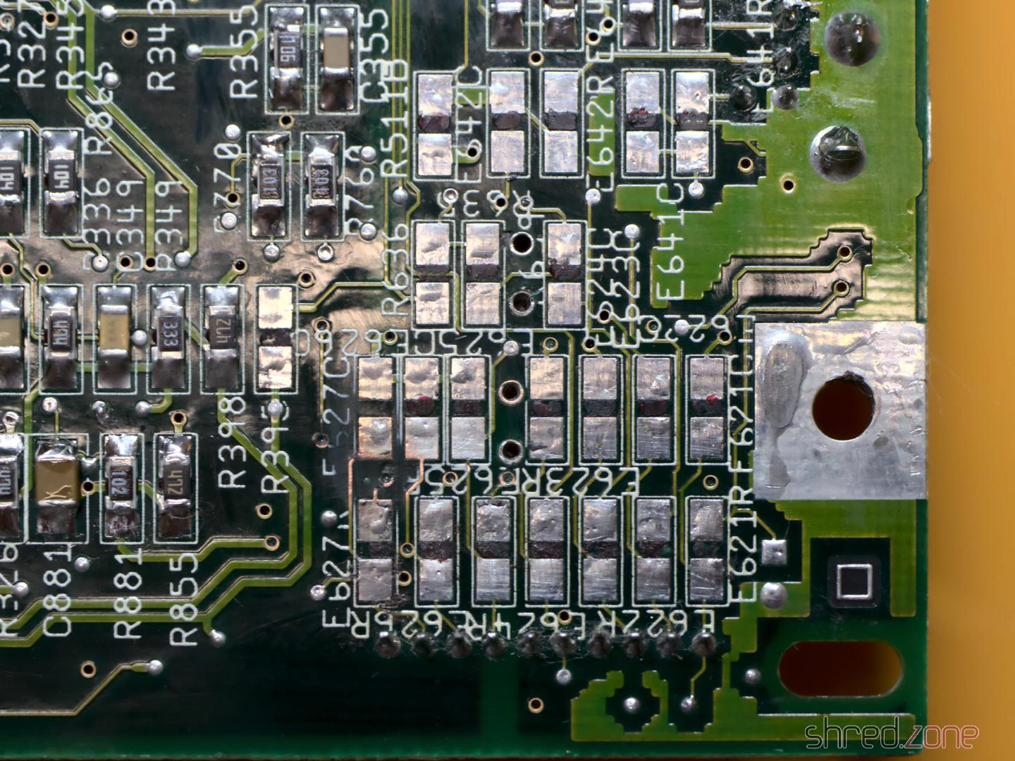
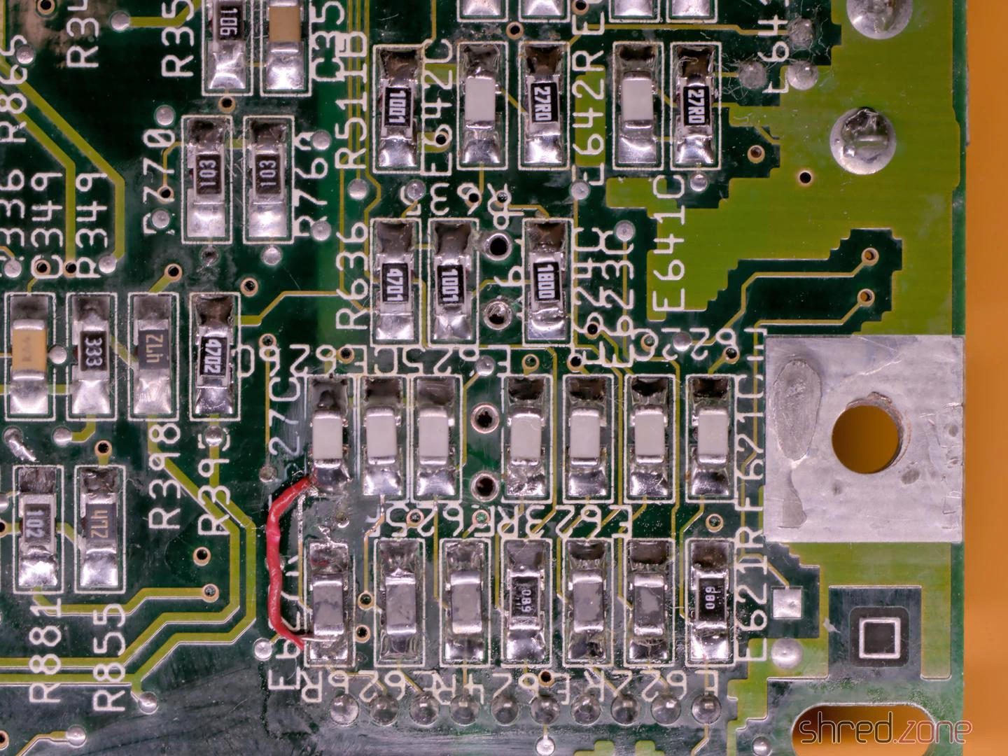
Unfortunately, I tore off a few pads on the 100µF capacitors in the process. I suspect the leaked electrolyte and the thermal stress of two recappings were simply too much for them. Something like this is annoying, but not the end of the world.
Afterwards, I soldered in new components and repaired the torn-off pads with bodge wire. For two SMD capacitors, the board alternatively offered the use of TH capacitors, which suited me very well. Visually, this corner doesn’t look like much anymore, but it should work again.
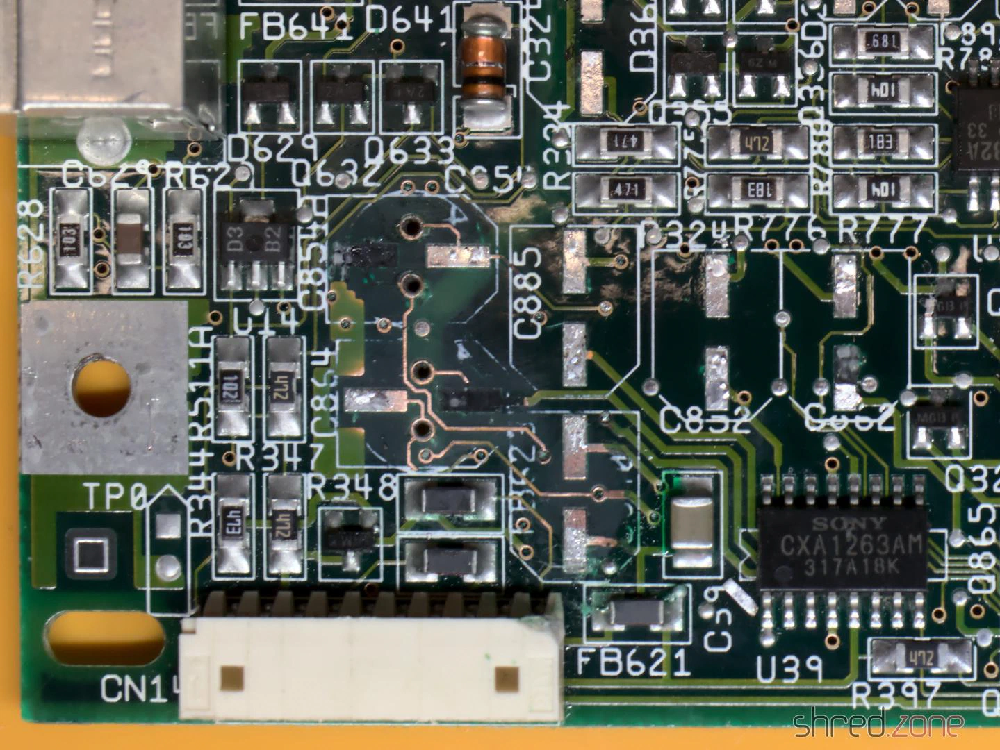
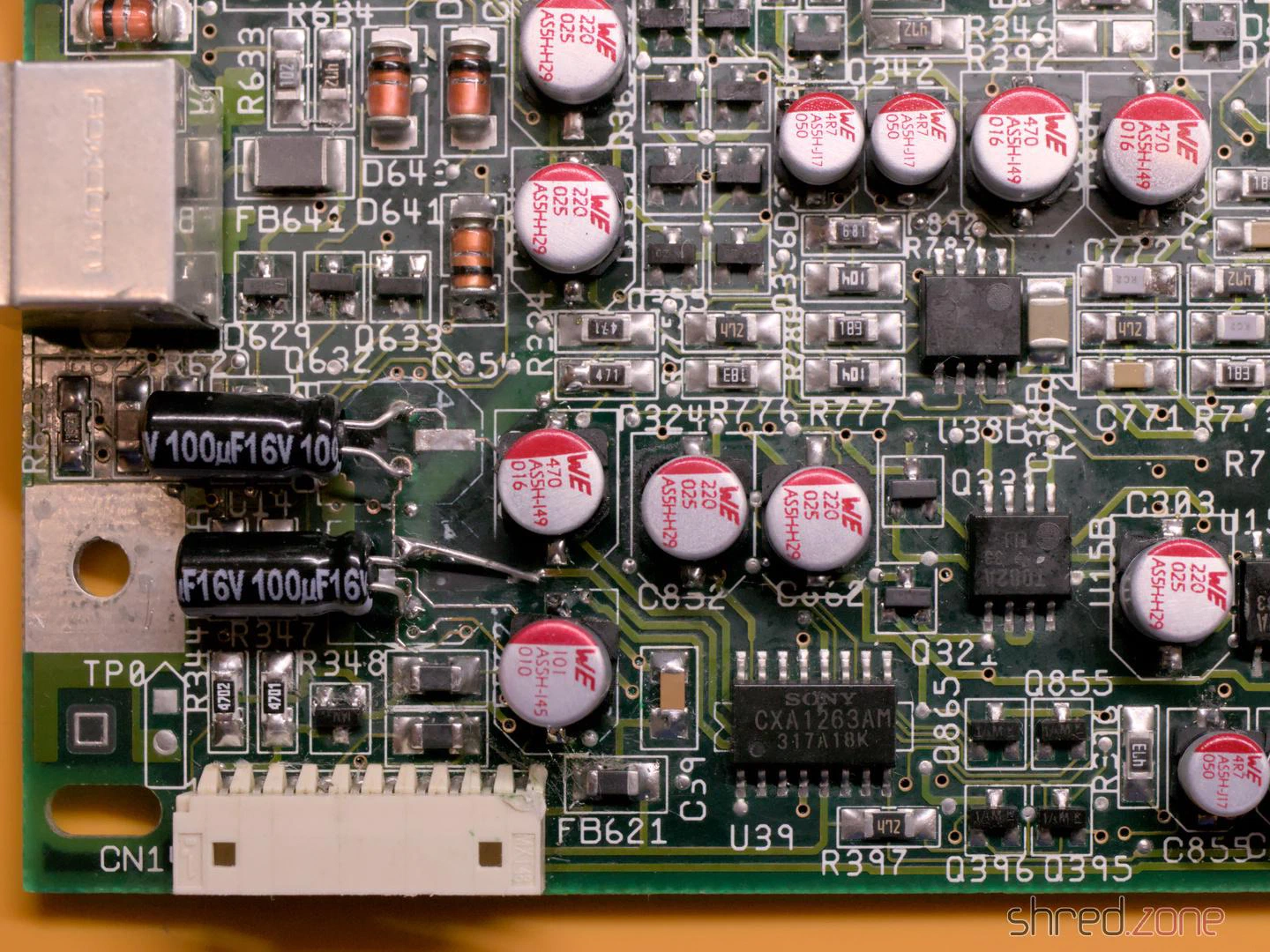
When I buzzed out the tracks and vias on the other 100µF SMD capacitors, I found further breaks at C236 and C237. They carry the luma and composite video signals and would be an explanation for why the picture stays black.
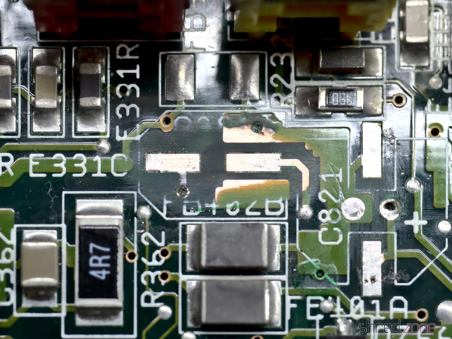
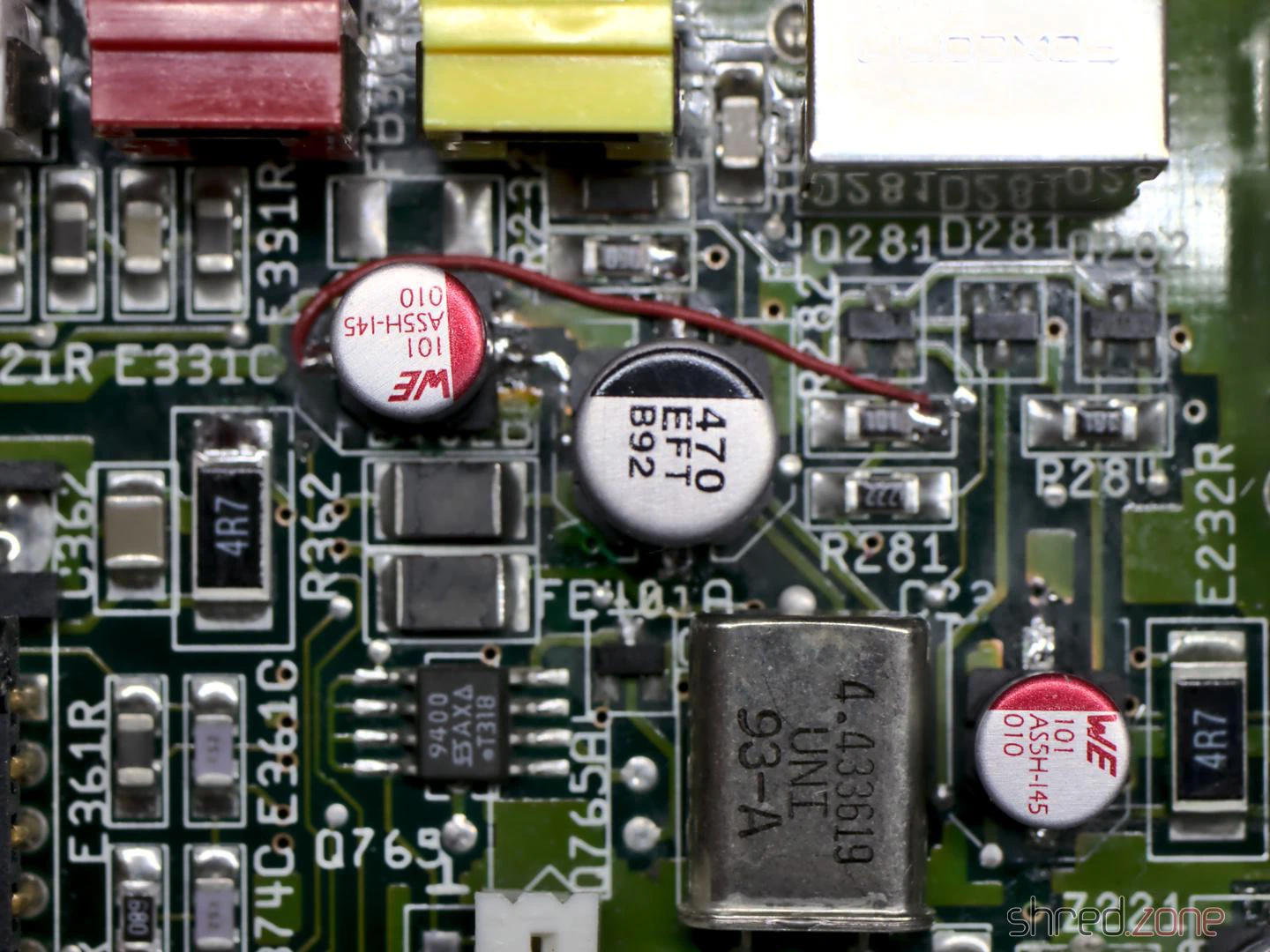
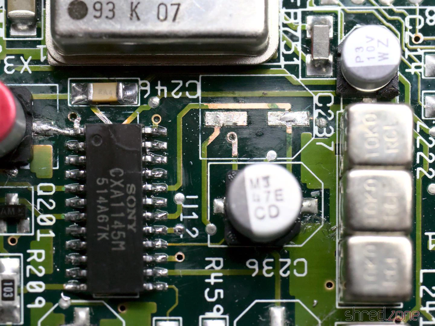
I also found a broken via near C409, which carries the CSYNC signal. As a result, the video sync signal is missing at the outputs. I repaired it by drilling out the via, exposing the connected tracks on both sides, then threading a thin wire through the hole and soldering it to the tracks. (Note: This only works if the via has no connection to one of the inner layers of the board, which was the case here.)
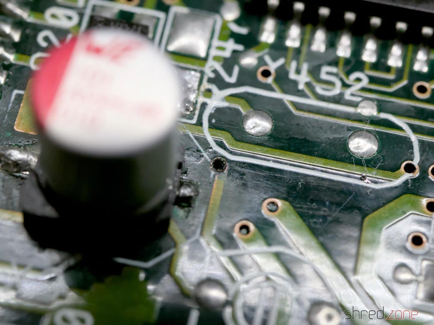
Overall, there were several reasons why the machine no longer showed a video picture.
By the way, two TH capacitors on the board have a peculiarity. At C408 and C811, the silkscreen shows the positive pole on the wrong side. This led to even Commodore soldering the capacitors in the wrong way round from the factory, which is why you will find quite a few CD³²s with bulging capacitors in this spot. I decided to solder in SMD capacitors there too, which can be soldered in as shown on the silkscreen.
So, power on, and to my surprise the Amiga worked again.
I checked all video and audio outputs and found a signal everywhere. The machine also ran stably. The mainboard was thus repaired and overhauled.
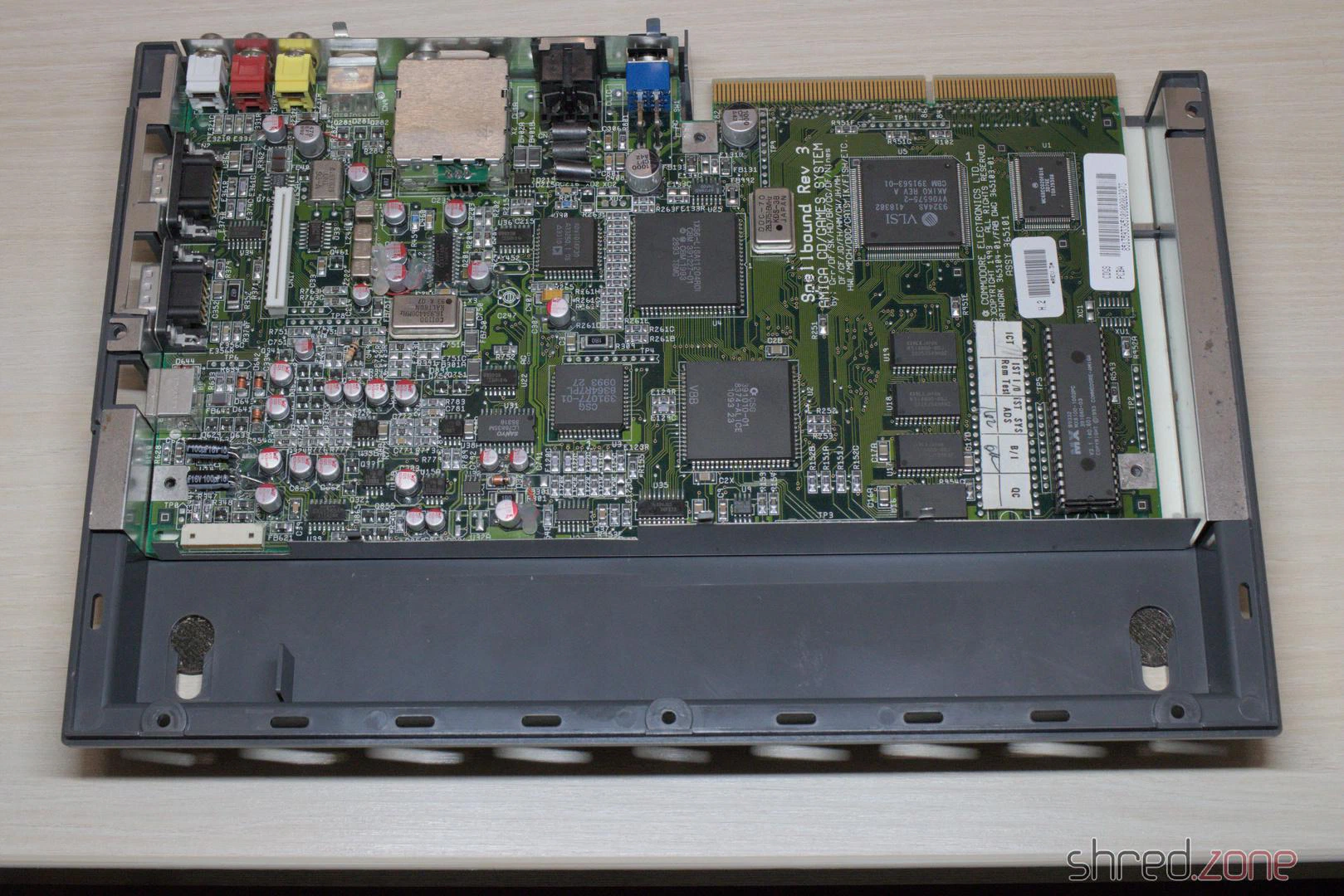
Even though it was an unexpectedly difficult affair, I am glad that I was able to repair the machine.
In the next part I will replace the laser module and calibrate the CD drive.