In the first part, I repaired the motherboard of an Amiga CD³² that was damaged by leaking capacitors and a botched restoration attempt. In this part, I am now replacing the laser unit and calibrating the CD drive.
The old laser unit in most CD³²s is likely worn out due to age and use. A common symptom is that the CD³² no longer plays CD-R media or only recognises music CDs. Incidentally, the CD³² generally does not recognise CD-RW media, as these use a dye instead of pits, which reflects too little light. This cannot be fixed even with a new laser unit.
Before we start, a heads-up:
WARNING: The laser unit is very sensitive to electrostatic discharge. Always take protective measures, e.g. by wearing an antistatic wrist strap.
Ensure that the laser is always covered when the computer is switched on (e.g. with a CD or a piece of paper). Do not look into the laser beam.
I would also like to mention at this point that I am not a trained technician. I have read guides on calibrating CD drives, and it worked for me. However, I do not claim that this is the best or most professional way to perform a calibration.
To replace the pick-up, a soldering iron and definitely an oscilloscope for the subsequent calibration are required. It might be possible without calibration, but the result will not be optimal.
Replacing the laser unit
First, I removed the CD drive from the case. Then I carefully separated the mechanical unit from the controller, and removed the four screws holding the frame of the mechanical unit. The metal shielding covering the pick-up must also be removed.
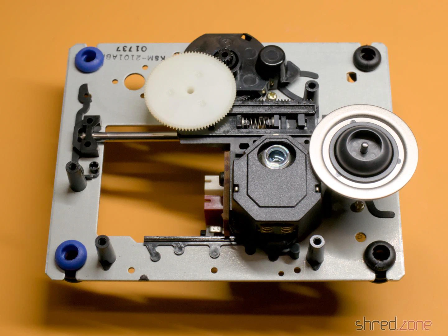
The pick-up is a Sony KSS210A. It is out of production for a long time, but replicas are offered on online marketplaces for a few euros. To remove the old unit, I first took off the white cog and then pulled out the metal rod (it is only held by a plastic clip that can be pushed to the side). While I was at it, I removed the old grease from the rod and the cogs, and then applied a little silicone grease. After that, I mounted the new unit and reassembled the CD drive in reverse order.
Important: Immediately after the new laser unit is connected to the controller, a solder blob on the laser unit must be removed! It protects the laser from static electricity, but would irreparably damage the drive controller if it is still present when switched on.
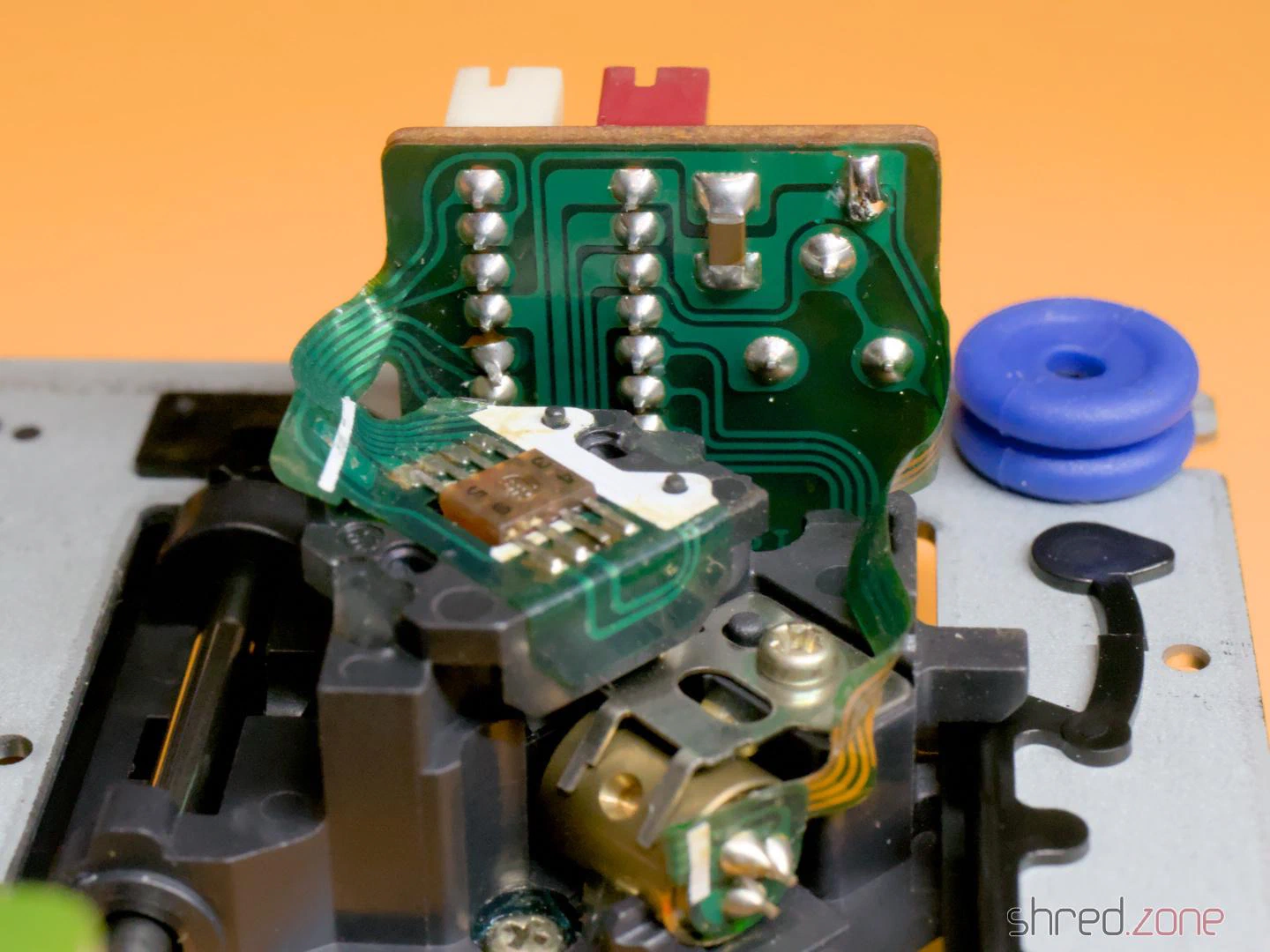
If you want to keep the original laser module, you should also apply a solder blob there before disconnecting it.
Preparation
I removed the metal shielding of the drive controller to perform the calibration. There I found a surprise: a tiny circuit board glued to the motherboard and connected with seven wires.
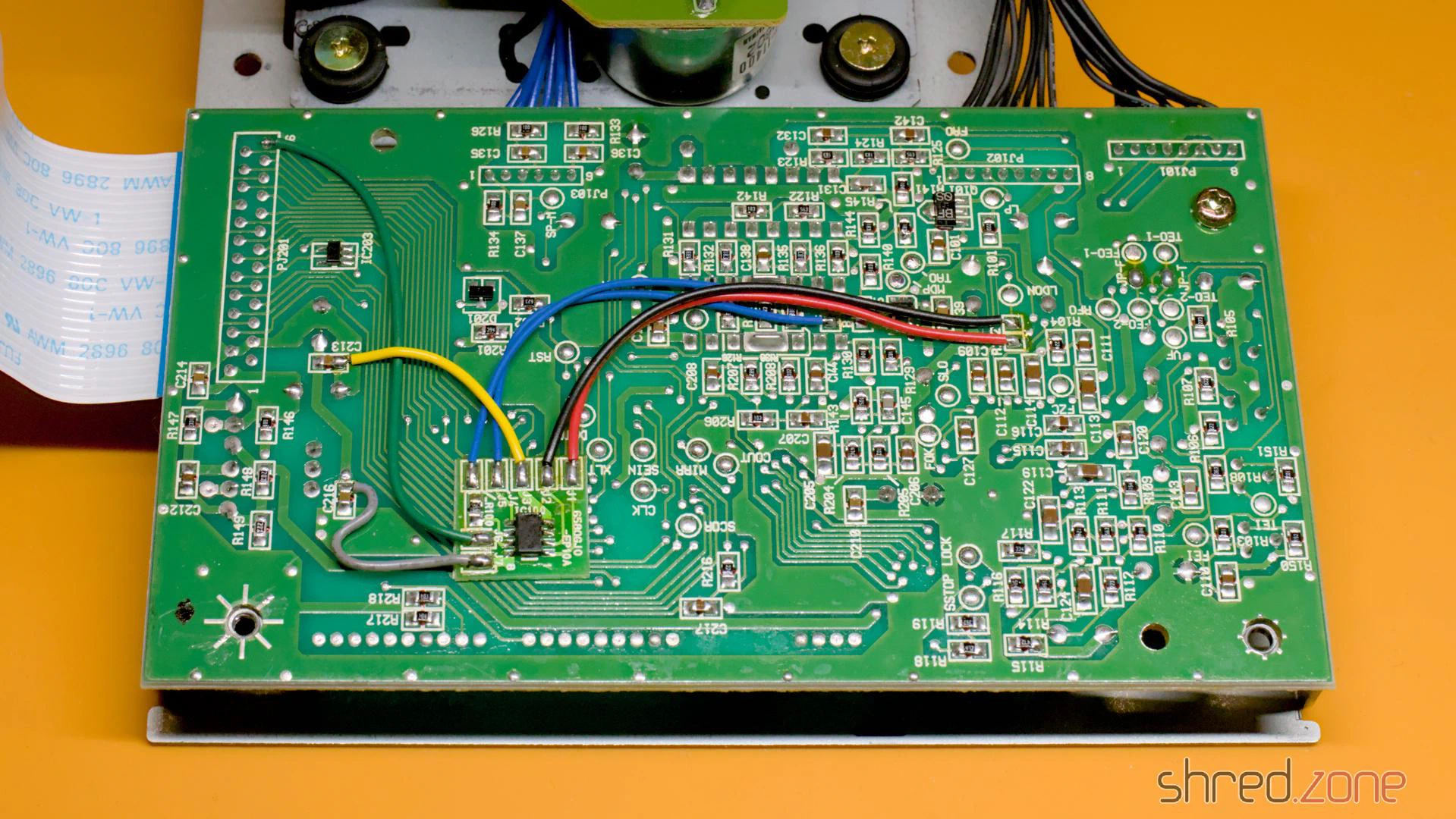
At first I assumed this might be a mod to bypass copy protection measures. However, the CD³² didn’t have a sophisticated copy protection system to bypass. Later I found the answer in a YouTube video: This modification cuts the power supply to the laser and the spindle motor as soon as the lid of the CD drive is opened. However, I could also find many photos of the controller board without the modification. I assume it was a product safety requirement so the CD³² could be sold on the German or European market.
Okay, back to the calibration. As a preparation, I soldered wires to the test points VF, RFO, TEO-1 and FEO-1. I recommend using different colours for this, it makes the calibration easier. Unfortunately, I only had red wire at hand, so I had to check every time which wire went where.
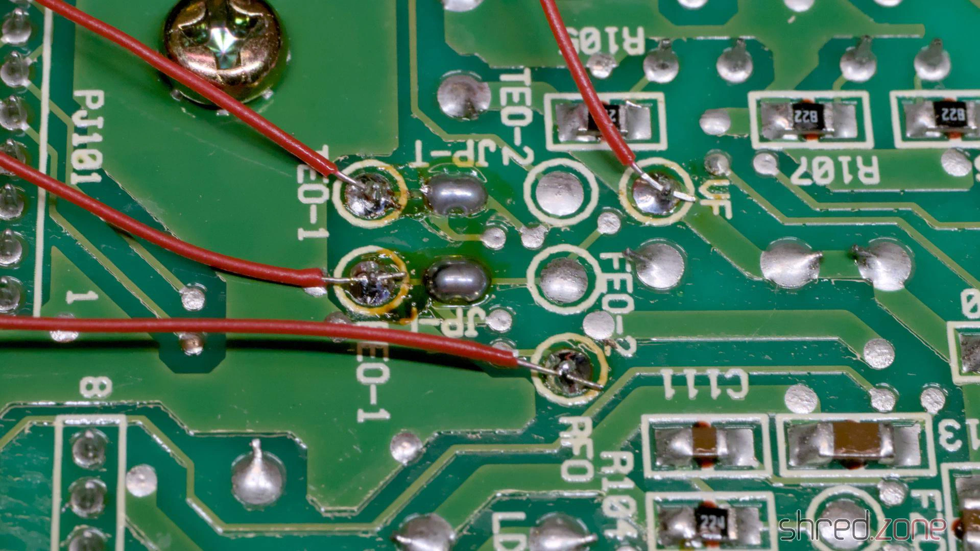
After that, I measured the current settings of the four potentiometers on the controller board and the potentiometer on the laser module with an ohmmeter, and wrote them down. If the calibration should go wrong for any reason, I could restore these settings at any time. A photo of the potentiometer positions would be far too inaccurate, by the way, better to measure!
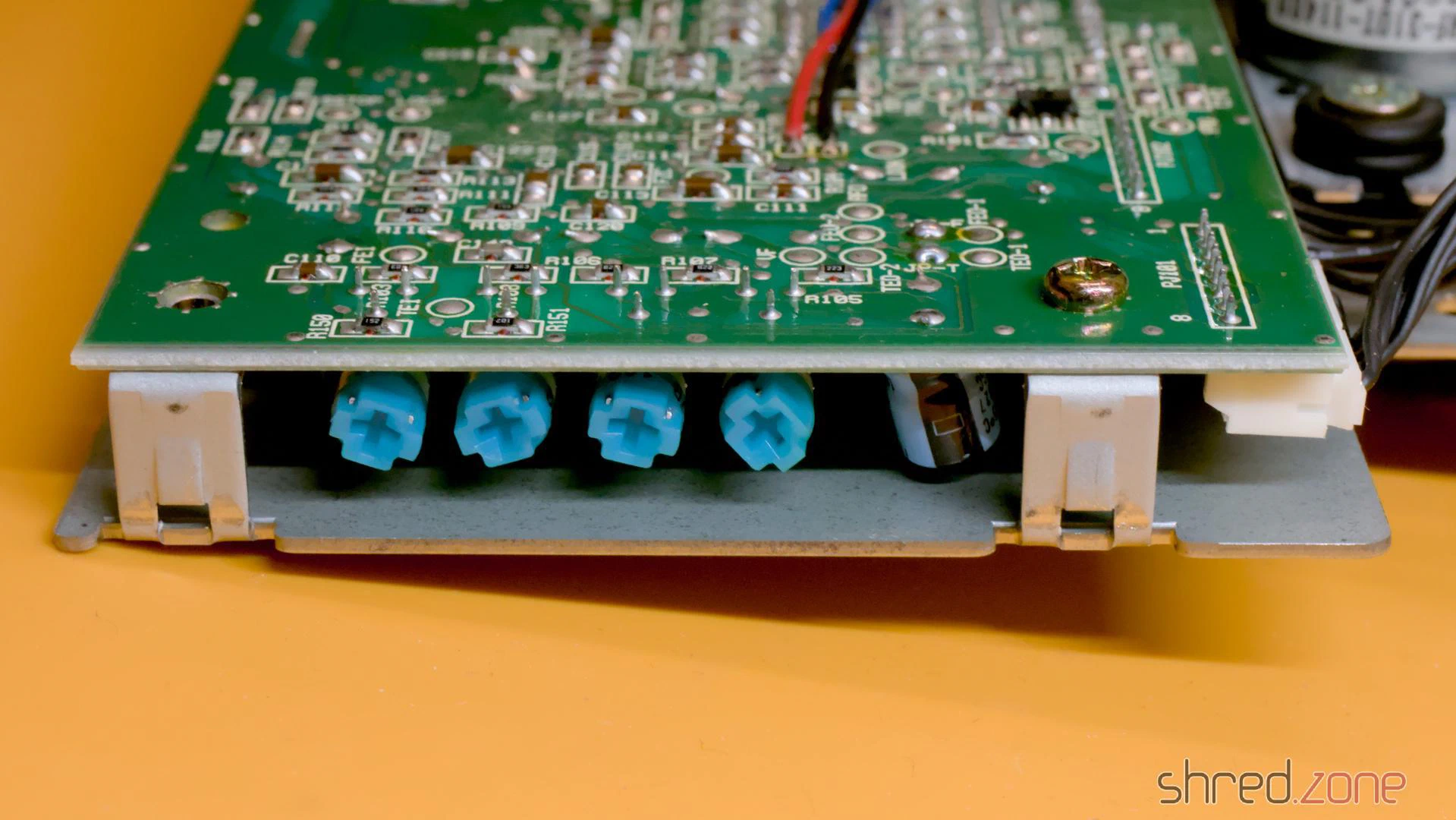
For the calibration, the drive must be reconnected to the motherboard. The top of the case (with the LEDs, the reset button, etc.) must also be connected, as the CD³² does nothing as long as the drive lid is open. The laser unit moves during operation and should have enough space for this.
To hold the CD on the spindle, I removed the spindle clamp from the inside of the lid and fixed the loose part in the middle with a little sticky tape. A magnet holds the clamp to the spindle and ensures that the CD does not slip.
Calibration
The actual calibration process is explained in this blog article by TSB. My attempts to explain it would be far worse. 😉
It turned out with my drive that the process didn’t work like that. After I had carried out the first steps of the calibration, the drive suddenly went on strike and didn’t read anything at all. Fortunately, I had noted down the potentiometer positions, so I could restore the original settings and start over.
Afterwards, I first calibrated the TEB pot until there were about 0 mV between TEO-1 and VF. The drive was still running after that. Only when I calibrated FEB as documented did it strike again. I undid this change and continued with the calibration of the laser power.
WARNING: Be extremely careful with the potentiometer on the laser module and only turn it in very small steps. Otherwise, the laser can be permanently damaged.
There may be a drop of varnish on the pot. It is advisable to turn the pot first while it is switched off to break the varnish, and then use the ohmmeter to reset it to the noted factory setting.
To calibrate the laser power, I connected the oscilloscope to RFO and ground. Then I put a music CD on the spindle and started track 1. The oscilloscope should now show a so-called “eye pattern”:
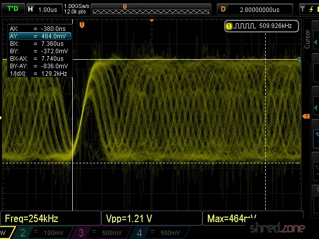
The tricky part is to adjust the pot on the laser module while the CD is playing. I adjusted it very carefully until I reached a peak-to-peak voltage of about 900 mV. 1200 mV should never be exceeded.
Then I adjusted the FEB pot on the controller board until I reached a maximum amplitude in the eye pattern.
The last two pots, FEG and TEG, are calibrated by measuring the test points FEO-1 and TEO-1 respectively against ground. The drive should be playing track 1 of an audio CD and be in pause mode during calibration.
I tried to find the ideal point where the signal on the oscilloscope is as smooth as possible and the correction noises of the laser optics are as quiet as possible. The goal is to find the best possible compromise. You will probably get the best results if you listen to the noises of the laser unit and follow your gut feeling.
The calibration is then complete and the CD³² can be reassembled.
Tip: Burn CD-Rs for the CD³² at the lowest speed your burner supports. This increases the contrast of the data on the CD. Also, prefer CD-Rs that are not transparent when held up to the light.