 A simple method to keep burglars away from your home is a TV simulator. It’s basically a device with some bright RGB LEDs showing color patterns that resemble those of a telly turned on. They are sold at many electronic retailers. However, some customer reviews say that the color patterns do not look very realistic, with some distinctive flashes and colors that are usually not to be seen on a regular movie. Besides that, the color patterns often repeat after about half an hour.
Actually, distinctive color patterns that repeat after a short time, are a major disadvantage. Experienced burglars might recognize the color patterns and figure out it’s a TV simulator. This would rather be an invitation than a deterrent.
So, let’s build a better TV simulator ourselves. It’s also more fun than buying something ready.
The Idea
What do we actually see when we watch a telly from outside a room? Usually there are colors with a medium saturation, changing slowly while the actors move or the camera pans. And there are very few hard cuts in the hue or brightness when the scene changes, when there is an explosion in an action movie, or something like that.
We could simulate these effects randomly, but what would look more realistic than using a real movie as a source? The idea is to squeeze a real movie stream into a sequence of RGB colors that are small enough to fit into an Arduino Uno with just 32 KByte of flash space.
You say that’s impossible? It isn’t! 😁
The Ingredients
I used the following parts for the TV simulator. They are rather cheap and can be purchased in many electronic shops:
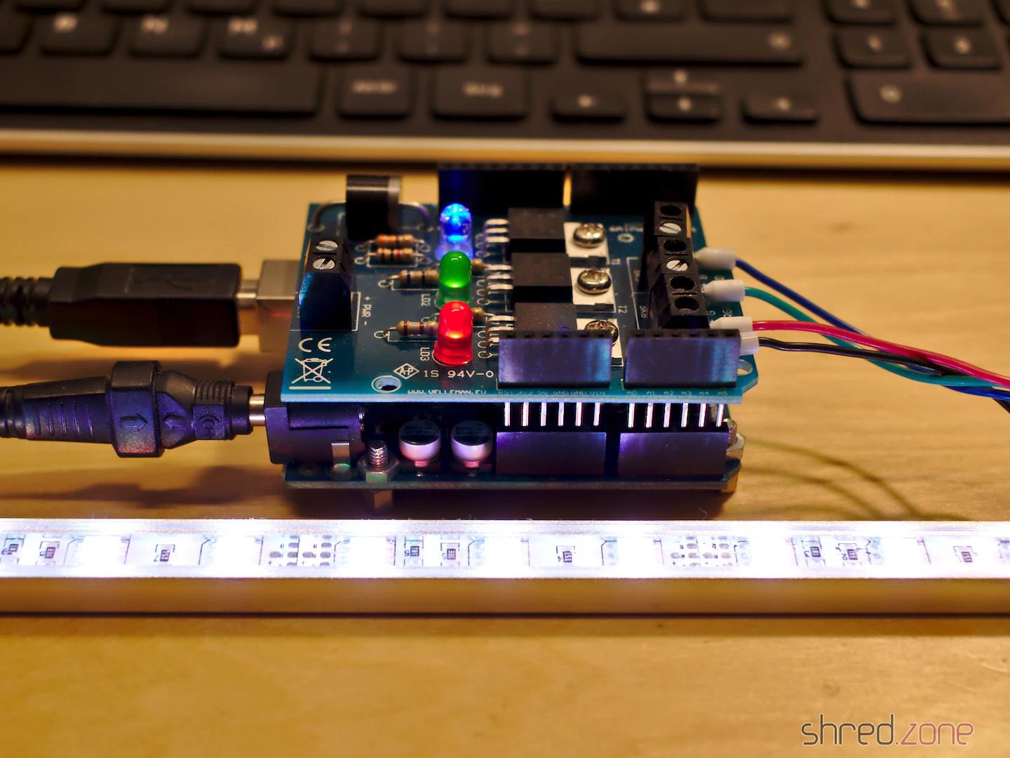
- Arduino Uno
- Velleman KA01 RGB shield. Any other RGB shield or a self-made solution should work as well, maybe with some minor modifications to the code.
- RGB LED strip (12 V, about 7 W, Common Anode)
- 12 V wall power supply for supplying the Arduino and the RGB LED strip (1 A or more)
Now just connect the RGB shield to the Arduino, and connect the LED strip to the RGB shield. That’s all, hardware-wise.
Caution: The RGB LED strip is a very intense light source that can cause permanent damage to your eyes! Avoid looking directly into the LEDs!
The Software
You can find the source codes of the Arduino sketch and the movie converter in my Codeberg repository.
The movie converter is written in Python and uses OpenCV. Basically, it converts an mpeg stream to a source code that can be included in the Arduino sketch. But there are also a few parameters you can toy around with to improve the result.
The next step is to compile the sketch and upload it to the Arduino. The movie should start playing back immediately.
Actually, the encoding is so efficient that you can cram a full-featured movie of 2 hours into the tiny Arduino memory.
Behind the Curtains
How does the converter work? And why is it so efficient?
First of all, as nobody is going to actually watch the simulated movie, we can remove the audio tracks and drastically reduce the frame rate. 10 frames per second is the default, but if the Arduino memory is too small for your movie, you can even go down to 5 frames per second.
Also, unlike a real TV, the RGB shield is only able to generate a single color, so all we need is the movie as a stream that is scaled down to a single pixel.
The converter software now analyzes the single-pixel movie stream. For soft color changes (like fixed camera positions or slow camera pans), it only stores the target color and the time it takes to reach it. When playing back, the Arduino will just gradientally change from the current color to the target color in the given time. For hard color changes (like jump cuts or in action scenes), the change to the target color will happen immediately.
Movies mostly have soft color changes, and only a few hard changes, so several seconds of video material can be stuffed into just a few bytes. This is why the converter is so efficient.
The algorithm is pretty simple, but gives amazingly good results. Especially on action movies, with a lot of cuts and striking action scenes.
The luftdaten.info project offers a build guide for a fine dust sensor. It’s cheap and easy to put together even with little electronics knowledge. You can get the parts in various electronics shops and nowadays even on Amazon.
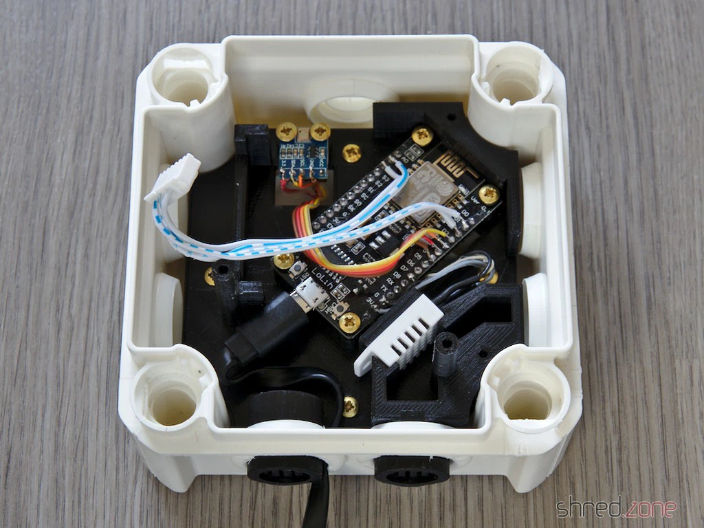
The original kit uses two plastic pipes as a casing. They’re cheap and easy to get in any DIY store, but they don’t look particularly great. I chose a standard UV and weatherproof outdoor junction box as the casing instead. A custom-designed 3D-printed frame is placed inside, and the electronics are mounted on it.
The frame already has a wind tunnel for the drawn-in air, so unlike the original instructions, you don’t need a hose. Grids in front of the air vents stop insects from crawling into the case. Also, unlike some other printed solutions, the fine dust sensor is aligned as specified by the manufacturer, and the intake hole is protected from light.
Unlike the original guide, though, you can’t avoid picking up a soldering iron here.
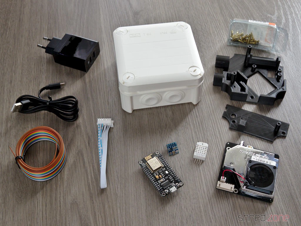
You’ll need the following parts:
- 1x set of 3D-printed frame parts
- 1x OBO Bettermann T60 junction box with plug-in seals
- 1x NodeMCU ESP8266 (by Lolin, other brands might not fit)
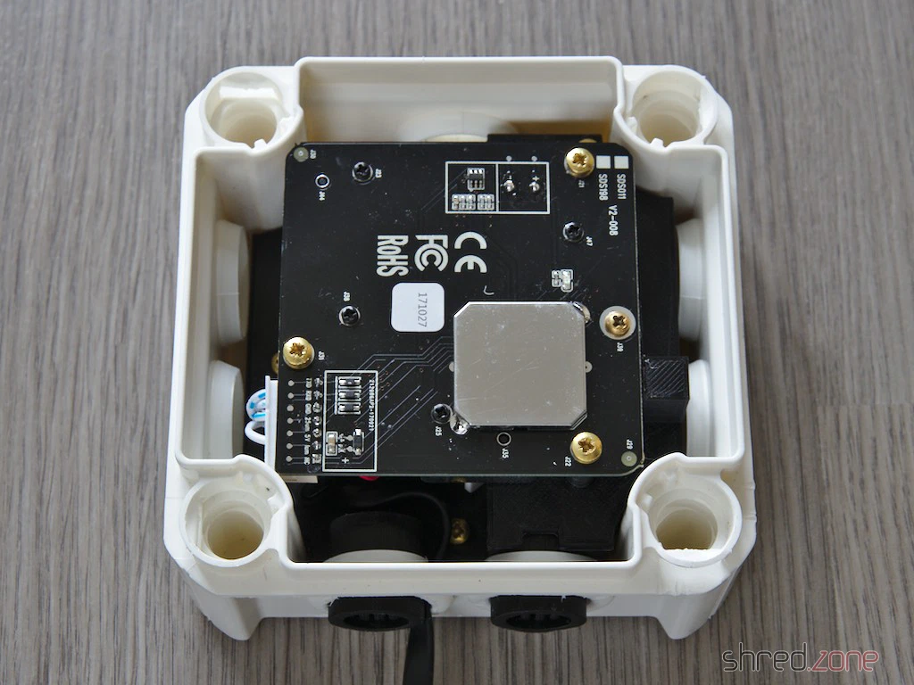
- 1x ILS-Nova SDS011 fine dust sensor
- 1x DHT22 temperature and humidity sensor (usually optional, but required here as it seals off a hole in the wind tunnel)
- 1x BMP180 temperature and air pressure sensor (optional)
- 11x wood screws 3.0 x 12 mm
- 4x wood screws 3.5 x 12 mm (or four more 3.0 x 12 mm)
- A bit of ribbon cable
- Some heat shrink tubing
- USB cable (flat)
- USB power supply (an old mobile phone charger is absolutely fine, the sensor needs less than 200 mA)
You don’t need any particularly UV or weatherproof filament for the printed parts, since they’re protected by the junction box. The filament just shouldn’t be so brittle that the screws break it. And it should be as dark as possible so no stray light gets into the dust sensor’s opening. I used basic black PLA.
Important: The print should be done without supports, as they are really hard to remove afterwards and could block the air duct. The parts are designed so they can be printed with PLA even without supports.
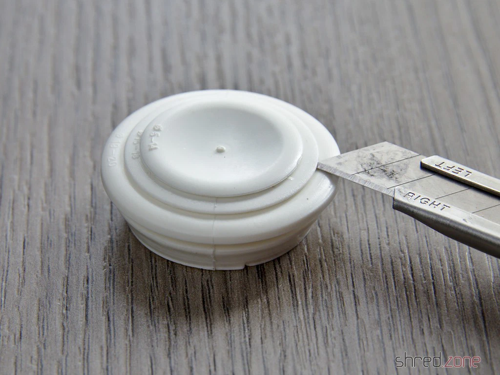
First off, remove the two plug-in seals from one side of the junction box and cut them open at a 19-20 mm diameter.
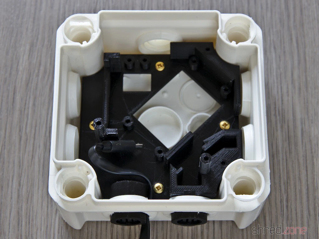
Now poke the USB cable through the left hole, then pop the lower support frame in from the inside and screw it down with the 3.5 x 12 mm screws. The casing can now be sealed up again with the plug-in seals.
It’s time to solder the electronics together according to the guide. The pins of the DHT22 should be protected with the heat shrink tubing. How to wire up the optional BMP180 air pressure sensor is explained in the FAQ. It’s best to install the firmware now and do a test run. Once the device is put together, it might be trickier.
Screw the NodeMCU and the BMP180 onto the base plate and plug the USB cable in. Just slot the DHT22 into its designated spot in the wind tunnel (see photo), it doesn’t need to be screwed down.
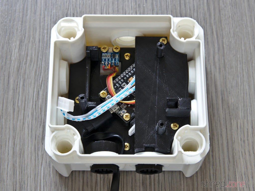
Next, pop the top plate on and screw it down. Connect the fine dust sensor, then carefully slide it into the air vent and screw it in place. You might need to snip a tiny bit off the plug to make it fit.
That’s it. You can pop the junction box lid on and secure it. The sensor is ready to go.
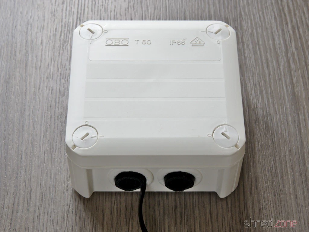
Mount the fully assembled sensor on an outside wall with the openings facing downwards. The casing should easily survive rain, snow, and hail. Since PLA goes soft at 60°C, you should avoid a spot in direct sunlight though. The sensor can also be operated lying flat, but the openings should be protected a bit from the rain then.
The sensor is powered via the USB cable. Since no data is transmitted, the cable can easily be several metres long.
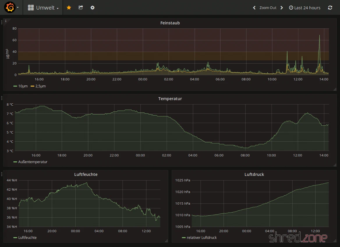
Once you’ve registered your sensor at luftdaten.info, you can see the measurement data on the map and download it as a CSV file. The current measurement data can also be queried directly via Wi-Fi in JSON format and stored in a database, for example. I use a little custom-programmed tool that fetches the data regularly, drops it into a PostgreSQL database, and displays it via Grafana.
Have fun tinkering! 😀
The sonar-gitlab-plugin is an useful plugin to connect SonarQube with GitLab. After pushing, the branch is inspected by SonarQube, and code smells are immediately commented in the commit.
Unfortunately, the error messages of that plugin are a little difficult to understand. It took me a while to collect this little cookbook of error fixes.
Unable found project for null project name
In SonarQube, as Administrator, select the project. Then in Administration ⭢ General Settings ⭢ GitLab, enter the project ID of your project and save it. The project ID is the group name in GitLab, followed by a slash and the name of the project, e.g.shred/timemachine.Unable found project for mygroup/myproject
In SonarQube, check that the project ID is correct and there are no spelling mistakes. In GitLab, make sure that SonarQube’s GitLab user is actually a member of the project, and that the user has Developer rights. I hit a strange bug in GitLab here. The SonarQube user was a member of the project, but still this error occured. When logging in as the SonarQube user, the project was not on the roll of projects. Removing and adding Developer rights to the user didn’t help. The only thing that finally worked was to add the SonarQube user to a different project, even if just for a moment. It seems to be a caching problem in GitLab.Multiple found projects for mygroup/myproject
You should never see this error, but if you do, be more specific with the projectID.
I just had a stream of objects I wanted to sort and convert to a list. Optionally it should also be limited to a maximum number of entries. Piece of cake with Java 8:
Stream<T> stream = collection.stream().sorted(comparator);
if (max >= 0) {
  stream.limit(max);
}
List<T> result = stream.collect(Collectors.toList());
Or so I thought… The code above throws an IllegalStateException at runtime, stating that the “stream has already been operated upon or closed”.
The cause should be obvious. However it took me a while to find it, so I am posting it in case other people (possibly you when you came here via search engine) get stuck at the same place. Stream operations are very likely to return a different Stream object. The limit() method is such an example. In my code above, limit() operates on the stream and returns a limited stream. However I just throw away the returned stream and invoke collect() on the original stream, which was now already operated upon.
The solution is simple:
if (max >= 0) {
  stream = stream.limit(max);
}
UPDATE: It seems that starting with hardware version 2, these switches have an actual web interface. Too sad my ones are version 1. 😢
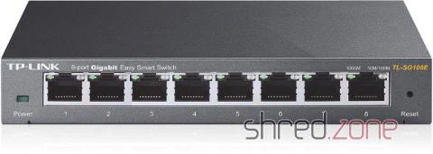 Frankly, I didn’t expect it and I was somewhat disappointed when I found out that the TP-Link TL-SG108E Easy Smart Switch (and its little brother TL-SG105E) cannot be configured via web browser. And I was even more disappointed when I found out that, even though Linux and MacOS were listed on the retail box, the configuration tool Easy Smart Configuration Utility runs on Windows only. And they mean it! When started in a Windows VM, the utility does not see any switches.
So the devices are rather cheap for a smart switch, but they still come with a price: no web interface.
However, thanks to some help in the interwebs, I was finally able to run the Configuration Utility on Fedora Linux. It’s not that easy, though.
Before we start, please be aware that this is a hack! I don’t know if running the Configuration Utility on Linux comes with side effects to the switch configuration and security. Maybe the switch can even suffer permanent damage that way. So use it at your own risk!
Running the Configuration Utility on Linux
The good news is: The Easy Smart Configuration Utility is written in JavaFX, so it runs on Linux even without Wine! First you need to download the utility from the TP-Link home page. It is a zip file containing an exe file. Unfortunately you have to run the exe file on a Windows machine to unpack it. I promise this is the only time you will actually need Windows. After that, you will find a file called Easy Smart Configuration Utility.exe in the installation directory. This is the only file we will need. Copy it to your Linux machine, and while you’re at it, also rename it from .exe to .jar. Yes, it’s just a Java archive file!
In a next step, you need to download and install the official Oracle Java on your Linux machine. OpenJDK will not be sufficient, as it does not contain JavaFX (yet).
When you are done, you should be able to start the Easy Smart Configuration Utility with this command:
java -jar "Easy Smart Configuration Utility.jar"
However, it does not find any switches. This is because the software discovers the switches via UDP broadcast, but unfortunately the interface is bound to the local IP address instead of any address, as it is required on Linux. We need to tweak the firewall…
If your system is running firewalld (e.g. on Fedora), execute these lines to add a firewall rule (and replace $your_ip with your local IP address):
firewall-cmd --add-port=29809/udp
firewall-cmd --zone=public --add-forward-port=port=29809:proto=udp:toaddr=$your_ip
If your system is running iptables, you need to execute these lines:
echo 1 > /proc/sys/net/ipv4/ip_forward
iptables -t nat -A PREROUTING -p udp -d 255.255.255.255 --dport 29809 -j DNAT --to $your_ip:29809
Now hit the Refresh button on the Configuration Utility, and your switches should finally appear. The GUI is still a little ugly with the input elements being too tall, but that is rather a cosmetical issue.
Firmware Upgrades
Firmware updates still failed with a strange error, and the switch needing to be powered off and on again. To successfully perform a firmware upgrade, I had to do these steps:
- Connect the switch directly to the computer, and disconnect everything else from the switch.
- Shut down NetworkManager (
systemctl stop NetworkManager). - Set up the ethernet interface manually (e.g.
ifconfig em0 192.168.0.2 up, it must be in the same subnet as your switch). - Invoke the iptables command from above again (use the IP address from the step above as
$your_ip).
After that, firmware updates finally succeeded, too.
Strange enough, the firmware image is transported to the switch via HTTP. It appears that there actually is a HTTP server running on the switch. An ASCII dump of the firmware file also reveals some HTML forms, so it seems like the switch is technically able to be configured via web frontend, but the feature has been disabled. Maybe it will be possible in a future firmware version, but I rather guess they found out that they ran out of memory when the switch was already on the production line. That would also explain the non-existing MacOS/Linux compatibility mentioned on the box.