 A good way to relieve the strain from your eyes while working on a PC, is to illuminate the wall behind your monitor. Jason Fitzpatrick wrote an interesting article about what bias lighting is and why you should be using it.
Many light sources can be used as bias lighting. I have used an old bedside lamp for a while. But what about something more stylish? What about a LED strip on an aluminum profile?
In this project, I am going to make a Wall Bias Lighting myself, and write a controller software for it. The source code will be released on my Codeberg profile eventually, so you will be able to customize it.
Proof of Concept
To make it a true premium lighting, I use a LED strip that consists of SK6812 RGBW LEDs. It can produce colors, but it also has separate white LEDs for a clean neutral white. Even better: Each LED can be addressed and the color changed individually. It would be possible to illuminate the wall behind the monitor in a bright white, while the visible parts of the strip are in a soft blue that won’t dazzle the eyes.
AdaFruit sells these LED strips under their brand name NeoPixel, but there are also no-name strips on the market that are fully compatible and considerably cheaper. The strips are usually sold on reels of up to 5 meters length. They can be shortened to the desired size with scissors, and have an adhesive tape on the back so they can be glued to aluminum profiles.
This is the bill of material for the first proof-of-concept phase of the project:
- An SK6812 RGBW LED strip with 60 LEDs per meter
- An aluminum wall profile for LED strips
- 1x AdaFruit Feather M0 Express
- 1x Level converter (read below)
- 1x 1000 µF/16 V capacitor, 1x 500 Ω resistor (read here why they are needed)
- 1x 5 V power brick. Each LED is said to consume up to 60 mA (I couldn’t find concrete figures), so you will need 18 W per strip meter if you want to set all four colors of all LEDs to maximum brightness.
The assembly was rather simple. First I cut the profile and the strip to the desired length and glued them together. Then I connected the strip to the power supply, and the strip’s data line to the Feather via the level converter.
The next thing on the to-do list was a quick test drive, to check if some of the LEDs are defective. So I installed CircuitPython on the Feather, and wrote a tiny test program that just cycles through the colors red, green, blue, and white. With this pattern, even a single defective LED would immediately catch one’s eye.
I turned on the power supply, aaaand… Nothing! 😲 All the LEDs stayed black.
I checked and double checked the wiring, but everything seemed to be correct. I tested my test program on the single NeoPixel that is mounted on the Feather, and it worked there.
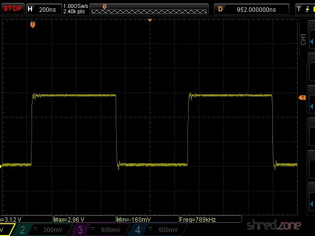
Puzzled, I connected my scope to the data line of the LED strip. It immediately revealed the culprit.
The Feather runs on 3.3 V, and so the signal on the data line has an amplitude of 3.3 V.
The LED strip runs on 5 V though, and also expects a signal amplitude of 5 V. The logic converter between the Feather and the strip is supposed to convert the 3.3 V signal to 5 V. However, the BSS138 based bi-directional logic level converter from my spare part box turned out to be too slow for this purpose. The output level starts at 3 V and then ramps up to 4 V.
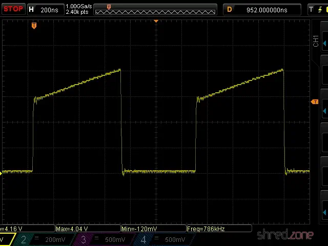
This is not sufficient for the SK6812, which needs a 5 V signal and a very precise timing with clean signal edges. Both was not given, so the LEDs stayed black.
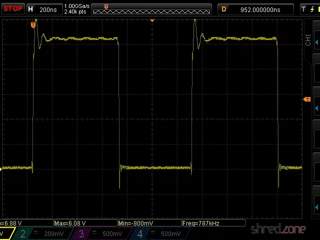
I replaced the logic level converter by a standard 74HCT125 buffer IC, and tried again. The LED strip immediately came to life and cycled through the colors. The scope now shows a clean (well, more or less clean) 5 V signal.
My proof-of-concept is working. 🎉 This is what the circuit looks like:
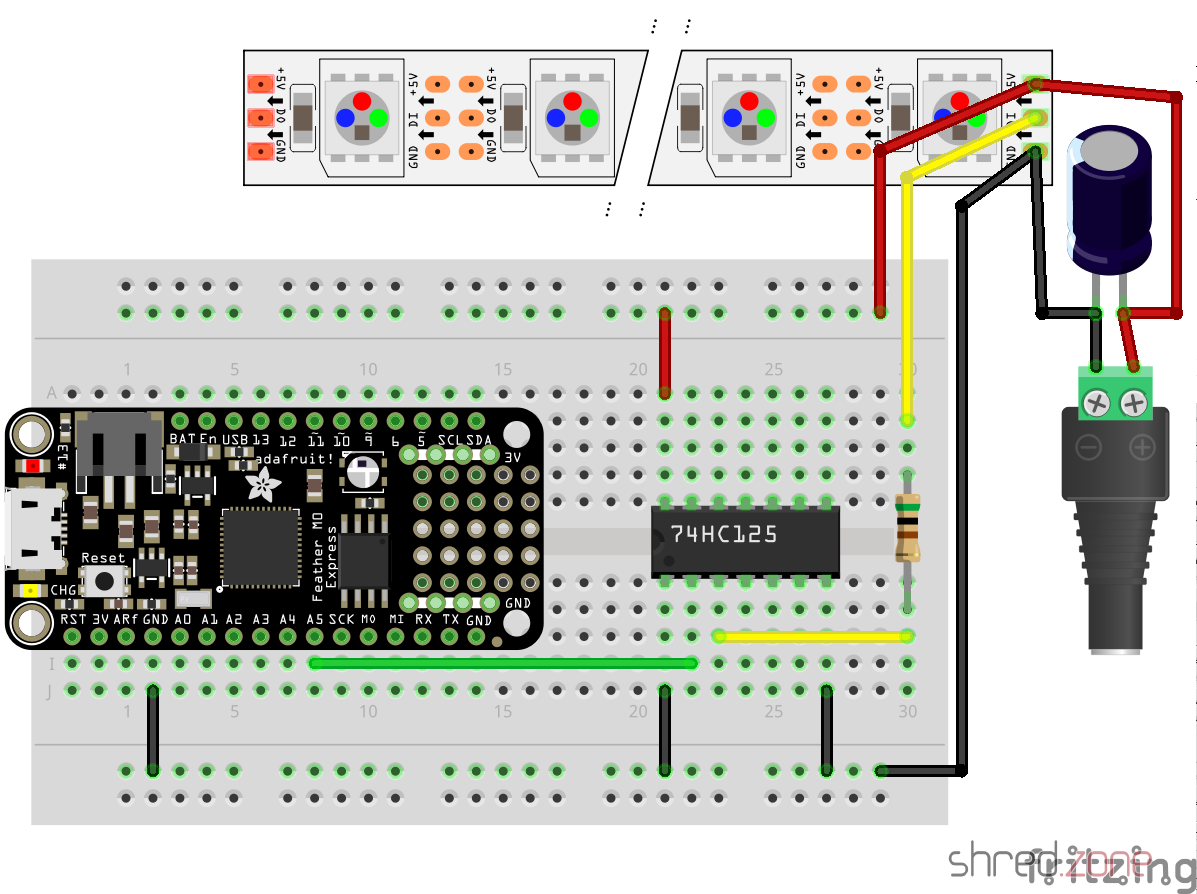
While the LED strip is powered by the power brick, the Feather is going to be powered by USB as long as I am developing the software. Later I will also supply the Feather with LED power, so it runs stand-alone.
Never connect the Feather to an USB port while it is supplied by an external power source. It could damage your computer.
What next? I’m going to add a power button, so I can turn the light on and off. For controlling the brightness and light effects, I am also going to add a display, a rotary switch, and another button. Stay tuned…
doxia-module-markdown is a Maven plugin that enables Markdown in Maven documentations. In version 1.8, the developers have moved from Pegdown to Flexmark as Markdown parser. It’s a good choice, as Flexmark is considerable faster and is still being maintained, while Pegdown officially reached its end of life in 2016.
However, with that switch, code blocks are not syntax highlighted any more. The reason is that the maven-fluido-skin uses code-prettify for syntax highlighting. It runs browser-side, highlighting all <pre> and <code> blocks selecting the prettyprint CSS class. This was true with Pegdown, but Flexmark selects a source class instead.
An obvious workaround is to use a small JavaScript snippet that adds a prettyprint class to all blocks selecting a source class, and then running prettyPrint() again. To do so, this block needs to be added to the <head> section of site.xml:
<head>
  <!-- Workaround for https://issues.apache.org/jira/browse/DOXIA-571 -->
  <![CDATA[<script type="text/javascript">
    $(document).ready(function () {
      $(".source").addClass("prettyprint");
      prettyPrint();
    });
  </script>]]>
</head>
It’s hard to tell if this is a bug in doxia-module-markdown or in maven-fluido-skin. Also see my bug report at Apache’s JIRA.
This was a Google Plus comment that I have now moved to my blog as Google Plus is going to be closed. Thanks to Clement Escoffier for the inspiration.
 Just in time for Halloween 🎃, I made a ghost decoration that uses an Adafruit Circuit Playground Express.
The ceramic ghost is from a home decoration shop. I have put a little piece of sandwich paper inside, so the LED light can be seen through the ghost’s mouth and eyes.
The MicroPython source shows a candle light effect. For the flame, a mystic cyan color is used, so the ghost appears really spooky. 👻
If you copy .wav files to the Circuit Playground, a random sound effect is played from time to time. I found nice free sound effects on soundbible.com that surely give everyone the chills. The sound files should be converted to mono and 16 kHz sampling rate, so they fit into the tiny Playground Express memory. The sound effects can be muted using the switch on the Playground, if they should become too annoying. 😉
This is the code.py file that is to be copied to the Circuit Playground. The candle simulation was inspired by an example at AdaFruit. I made the candle color configurable and added the sound effects.
import math
import os
import random
import time

from adafruit_circuitplayground.express import cpx
import audioio
import board
import digitalio

CANDLE_COLOR = (0x00, 0xC0, 0xFF)
MIN_BRIGHTNESS = 64
MAX_BRIGHTNESS = 191

EFFECT_COLOR = (0xFF, 0x00, 0x00)
STEPS_BEFORE_EFFECT = 100

def split(first, second, offset):
    if offset != 0:
        mid = ((first + second + 1) / 2 + random.randint(-offset, offset))
        offset = int(offset / 2)
        split(first, mid, offset)
        split(mid, second, offset)
    else:
        level = math.pow(first / 255.0, 2.7) * 255.0 + 0.5
        cpx.pixels.fill((
            min(255, int(level * CANDLE_COLOR[0] / 256)),
            min(255, int(level * CANDLE_COLOR[1] / 256)),
            min(255, int(level * CANDLE_COLOR[2] / 256))
        ))
        cpx.pixels.show()

def colorShift(start, end, time):
    for i in range(1, time):
        j = time - i
        cpx.pixels.fill((
            min(255, int((start[0] * j + end[0] * i) / time)),
            min(255, int((start[1] * j + end[1] * i) / time)),
            min(255, int((start[2] * j + end[2] * i) / time))
        ))
        cpx.pixels.show()

cpx.pixels.brightness = 0.4
cpx.pixels.auto_write = False
cpx.pixels.fill((0, 0, 0))
cpx.pixels.show()

sounds = [f for f in os.listdir() if f.endswith('.wav')]

count = 0
prev = (MAX_BRIGHTNESS + MIN_BRIGHTNESS) / 2

while True:
    lvl = random.randint(MIN_BRIGHTNESS, MAX_BRIGHTNESS)
    split(prev, lvl, 32)
    prev = lvl
    count += 1
    if (count > STEPS_BEFORE_EFFECT):
        count = 0
        if cpx.switch:
            oldcolor = cpx.pixels[0]
            cpx.pixels.fill(EFFECT_COLOR)
            cpx.pixels.show()
            cpx.play_file(random.choice(sounds))
            colorShift(EFFECT_COLOR, oldcolor, 10)
 In the latest ACME draft 15, Let’s Encrypt introduced POST-as-GET requests. It is a breaking change that is not downward compatible to previous drafts.
This brought me into an uncomfortable position. While the Pebble server enforces the use of POST-as-GET, other servers don’t support it yet, like the Let’s Encrypt server. For this reason, acme4j needs to support both the pre-draft-15 GET requests and the post-draft-15 POST-as-GET requests. Luckily I have found a solution that is totally transparent to the user, at least as long as no other ACME server is used.
This is how acme4j v2.4 works:
- If you connect to Boulder via an
acme://letsencrypt.orgURI, acme4j falls back to a compatibility mode that still sends GET requests. Let’s Encrypt has announced a sunset date for GET requests on November 1st, 2019. You are safe to use acme4j v2.4 (and older versions) up to this date. - If you connect to a Pebble server via an
acme://pebbleURI, the new POST-as-GET requests are used. - If you connect to a different server implementation via
http:orhttps:URI, acme4j sends POST-as-GET requests now. This is likely going to fail at runtime, if the server you connect to does not support draft-15 yet. - As a temporary workaround, you can add a
postasget=falseparameter to the server URI (e.g.https://localhost:14000/dir?postasget=false) to make acme4j enter the fallback mode and send GET requests again.
As soon as Let’s Encrypt supports POST-as-GET on their production servers, I will remove the fallback mode from acme4j again. It just clutters the code, and I also have no proper way to test it after that.
Hint: Before updating acme4j, always have a look at the migration guide. It will show you where you can expect compatibility issues.
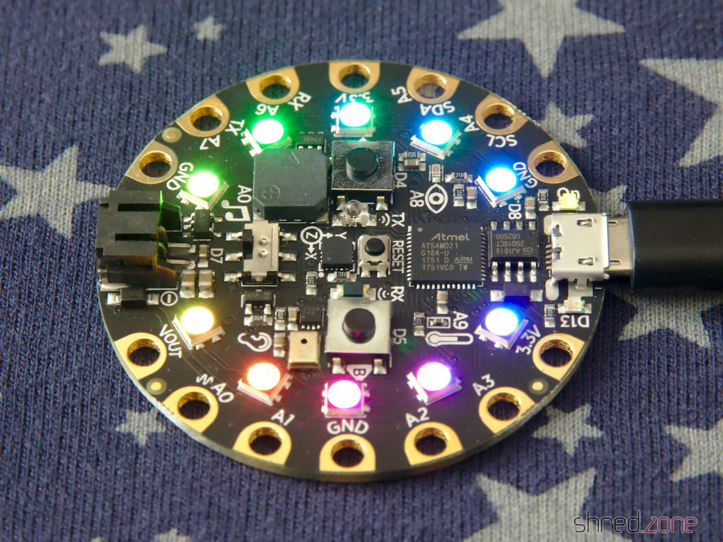 The season of long winter nights is coming, so I got myself an AdaFruit Circuit Playground Express for some home decoration.
My plan is to program it using CircuitPython, a MicroPython derivate that is adapted to the AdaFruit hardware.
CircuitPython must be installed to the Circuit Playground first, which turned out to be difficult with Fedora Linux in a first attempt. The troublemaker was the ModemManager, which is still installed by default. It detects the serial port of the AdaFruit device, and then hogs this resource because, well, it might be a modem. 🙄
My older readers certainly still remember what a modem is. 😉 But to make a long story short, almost no one is using a serial modem nowadays, so the ModemManager does not serve any useful purpose. However, it cannot be removed, because other important packages still depend on it. The only way is to stop it permanently:
sudo systemctl stop ModemManager
sudo systemctl disable ModemManager
After that, I could finally install CircuitPython to the Circuit Playground. First I downloaded the matching uf2 file. After that, I connected the Playground via USB, and changed to the bootloader mode by pressing its reset button twice (like a double-click).
The Circuit Playground is now mounted as an USB drive called CPLAYBOOT. All there is to do now is to copy the uf2 file to this drive. The Playground automatically reboots after that. If everything went fine, it will come back as an USB drive called CIRCUITPY.
The next step is to install the AdaFruit libraries to that drive. I downloaded the latest library bundle that matched my CircuitPython version, and just unpacked it to the CIRCUITPY drive.
That’s it… All there is to do now, is to open the code.py file in an editor and change the code. It is immediately executed when it is saved.
For a start, there are a lot of code examples for the Circuit Playground Express on the AdaFruit web site.