 Note to myself, but maybe you found this article via search engine… 🙂
Symptome: You are trying to post-process a Canon CR3 RAW image file with Darktable, but it doesn’t show any CR3 files.
Reason: Darktable uses LibRaw for reading CR3 files, which in turn uses exiv2. New file formats are not compiled into Fedora’s exiv2 though, presumably for licensing or patent reasons (see this bug report, tl;dr).
Solution: Uninstall Fedora’s Darktable version (either via dnf remove darktable or flatpak uninstall darktable), and install the flathub version via flatpak install darktable.
If you used the dnf version, you can copy the ~/.config/darktable directory to ~/.var/app/org.darktable.Darktable/darktable to keep your Darktable configuration.
 Sometimes you cannot choose your project, but the project chooses you. This one is about sending the status of a Home Connect clothes washer to MQTT using LoRa radio communication.
The project can be found at Codeberg.
The Problem
It all started when my clothes washer broke down. I replaced it with a new one, one that is also IoT capable by using the Home Connect network. I liked the idea because the machine is located in a shared laundry room at the basement of the building. If I knew about the progress and the remaining time, I could go to the basement and swap the laundry right on time, not too soon and not too late.
However, my WLAN does not reach the basement, so I couldn’t connect the washer to the Home Connect cloud. I tried PLC, but that made my DSL connection instable, so it wasn’t a solution either. I pondered about buying an LTE router, but the data tariff would cause monthly costs that I wasn’t really willing to pay.
Then I discovered LoRa, which is a radio communication technique that is specially designed for Long Range (hence its name) communication, with a range of up to several kilometers (on optimal conditions). It should be easy for LoRa to send data from the basement to my flat, and indeed, a first test was successful.
LoRa solves the problem of transporting the data. However, it comes with a price: The individual data packages are very small (about 50 bytes worst case), and in Europe there is also a 1% duty cycle restriction that needs to be respected. So it wasn’t possible to just connect the washer to the Home Connect cloud using LoRa as some kind of WLAN repeater.
Instead of that, I would have to connect to the washer directly, read its state and compress the information to what I actually need, before sending it. The problem is now that the connection between the appliance and the Home Connect cloud is proprietary and encrypted.
I found the solution to that problem in a blog post “hacking your dishwasher” by Trammell Hudson. By smart reverse engineering, Trammell was able to find a way to directly connect to his home appliances, without having to go through the Home Connect cloud. This was the last part of the puzzle that I needed.
Concept
 With Trammell’s work, I was able to connect to my washer and read its current state. Basically, the washer is sending key-value pairs via JSON, where the key seems to be a 16 bit integer, and the value is mostly also an integer, but could also be a boolean or a string. This information can be easily compressed into small LoRa packages, as I mostly need to transport numeric key-value pairs.
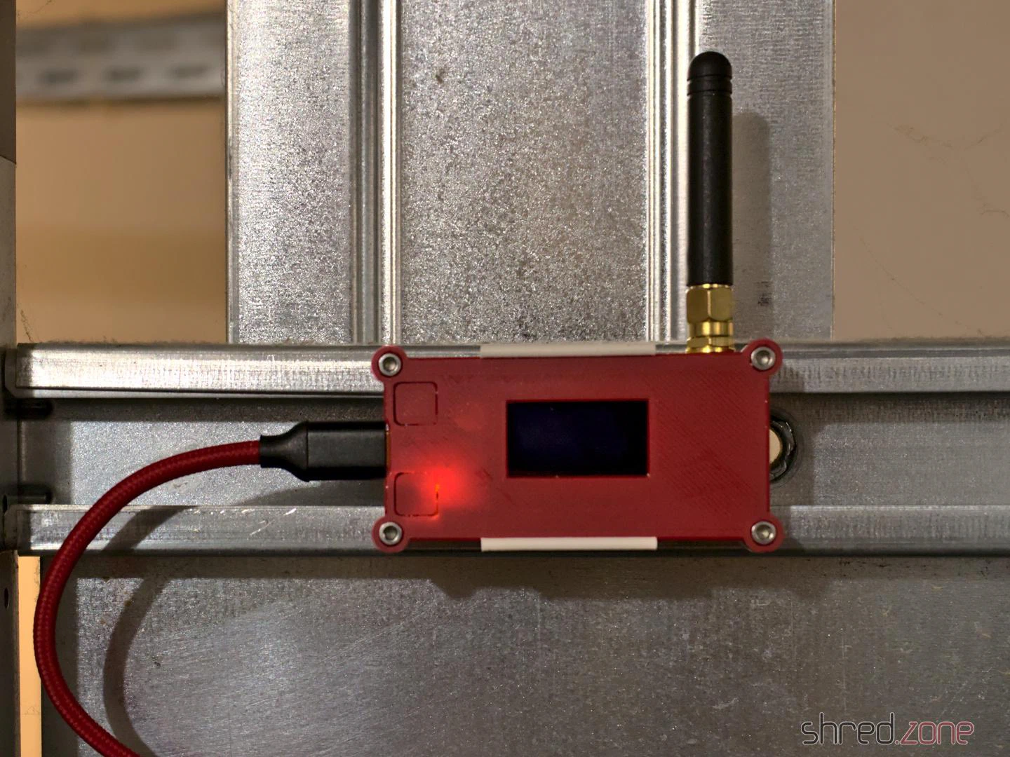
So there is a LoRa “sender” at the basement. It spawns a WLAN access point that the washer connects to. It then communicates with the washer, retrieves its state change events, compresses them, and sends them out via LoRa.
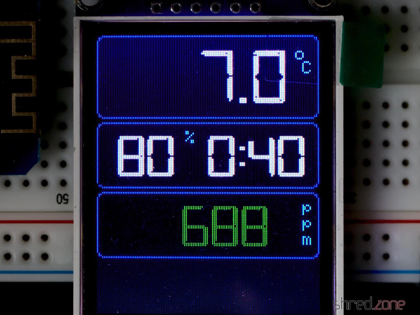
In my flat, a LoRa “receiver” uncompresses the information. From it, JSON bodies are generated and sent to my home automation’s MQTT queue. The generated JSON bodies resemble those sent by Home Connect. A display that is connected to MQTT shows the current progress and the remaining time of the washer. I will also get a message on my phone when the washer is completed, or if an error has occured.
Implementation
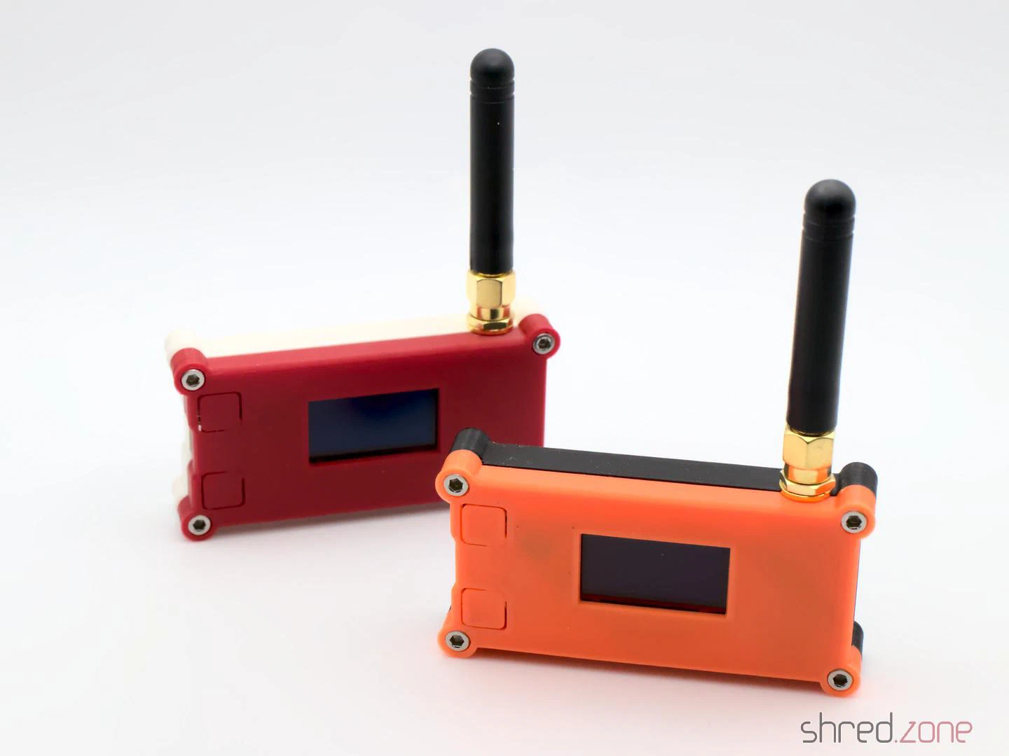
 For the implementation, I bought two Heltec LoRa32 V2 modules. They are based on an ESP32, with a LoRa module and an OLED on board. With a few modifications to the source, any other Semtech SX1276 based LoRa module can be used. For a proper housing, I created a 3D printed minimal Heltec LoRa32 V2 case.
Thanks to Trammell’s hcpy source code, it was surprisingly simple to write a C++ class for the ESP32 that opens a web socket connection to the washer and starts communicating with it.
As mentioned above, the washer is sending JSON messages that contain mostly integer based key-value pairs. To stuff as much information as possible into a single LoRa packet, I came up with a simple compression. The first byte is stating the type of information, followed by a 16-bit integer key, optionally follwed by the value. These are the possible types:
- 0: Represents the constant
0(so no value needs to be transported) - 1: Represents an unsigned 8-bit integer (so the value consumes 1 byte)
- 2: Represents a negative unsigned 8-bit integer (the positive value is transported, and then negated on the receiver side)
- 3,4: The same, but for 16-bit integers (the value consumes 2 bytes)
- 5,6: The same, but for 32-bit integers (the value consumes 4 bytes)
- 7: A boolean constant
false(so no value needs to be transported) - 8: A boolean constant
true(so no value needs to be transported) - 9: A string (followed by the null-terminated string as value)
These key-value pairs are collected until the LoRa package is full or the sender is flushed. A length byte is added that contains the total length of the pairs, so the receiver is able to unpack all of them again.
To secure the communication, a SHA256 based HMAC is generated. A random 16 bit package number is added as well, which is used by the receiver for acknowledgement. Finally, the package is encrypted using AES256.
The receiver side will unencrypt the package and generate an HMAC, using a shared secret. If the HMAC matches, an acknowledge package with the package number is sent back to the sender. After that, the payload is uncompressed and converted to JSON strings that are sent to MQTT.
It is important to know that the transport encryption is not state-of-the-art. There are several sacrifices that had to be made to keep the LoRa transport small and simple:
- Only the first 4 bytes of the MAC are used, for space reasons.
- The RSA256 encryption does not use a mode of operation, mainly because it would be hard to re-synchronize the LoRa connection if a package was lost. On the other hand, we are only sending the washer state. If someone would want to find out whether the washer is running or not, they could just check if a package has been sent within the past minute.
- The transport is not secured against replay attacks. The receiver should provide a random nonce, which is then used by the sender for the next package. This is something that should definitely be addressed.
So the LoRa connection provides an acceptable encryption, and is also protected against lost packages, since the sender will reattempt to send the package if there was no acknowledgement from the receiver.
Configuration
 The trickiest part of the project is probably the configuration.
To directly connect to the Home Connect appliance, an encryption key and (depending on the protocol) an initialization vector is required. Both parts cannot be retrieved by the public Home Connect API, but you need to trick the API into thinking that you are connecting from the Home Connect app. This is where Trammell’s hcpy project comes into play. It will let you log into your Home Connect account, and then extract a profile of your appliance and writes it into a config.json file. This file is required for setting up my project.
The config-converter.py in my project will take this config.json file and extract all the necessary parts from it. It will print the appliance’s key and iv values for your sender/config.h. It will also create a new random shared secret for the LoRa encryption. And last but not least, it will create a receiver/mapping.cpp file, which is used to convert the integer keys and values to strings similar to the Home Connect API.
If you came this far, you made the hardest part. After that, the LoRa transceivers need to be configured. Unfortunately the parameters depend on the country where the sender is used, so there are no general default settings.
The following values are proposals and are only valid for countries of the EU. You are responsible to find the correct settings for your country. Failure to do so may result in legal problems, claims for damages, and even imprisonment.
LORA_BAND: This is the frequency used for LoRa transmissions. For EU countries this is usually867E6.LORA_POWER: The power of the LoRa sender, in dB. For EU countries this must be 14 or less.LORA_PABOOST:truefor EU countries.LORA_SPREADING: The spreading factor. For EU countries, values between 7 and 12 are allowed. Higher values span longer distances, but also exhaust the permitted 1% duty cycle sooner. You should use the lowest possible value that gives a stable LoRa connection, and rather try to enhance reception by finding a better place for the LoRa devices or by using better antennas. The value should be 9 or less, as the duty cycle limit is likely to be exceeded with higher spreading factors.LORA_BANDWIDTH: The bandwidth, must be125E3in EU countries.LORA_SYNCWORD: A sync word. You can choose basically any values, or just use the default0x12.
Make sure that the sender and the receiver are using the same settings, otherwise the transmission will fail.
The other settings are mainly about the WLAN access point for your appliance, the WLAN settings of your home network, and the credentials to access your MQTT server.
And that’s it! Actually it was quite a fun project, and I learned a lot about ESP32 programming and LoRa networks. I also spent way too much time with it, but maybe it will pay off because I get the laundry done sooner now.
 On January 11 2021, Let’s Encrypt will change the default intermediate certificate from the cross-sign IdenTrust DST Root X3 certificate to their own ISRG Root X1 certificate.
The good news: The ISRG certificate is widely trusted by browsers by now, so the transition will be unnoticed by most users.
The bad news: The ISRG certificate is not included in Android devices before “Nougat” 7.1. These devices will show an error when trying to access sites that are signed with the new intermediate certificate. According to Let’s Encrypt, stunning 34% of the Android devices out there shall be affected.
To mitigate the problem, Let’s Encrypt provides an alternate certificate that is still cross-signed with the IdenTrust DST Root X3 certificate. If you have a web service that is accessed by a relevant number of older Android devices, you may want to use that alternate certificate. It will be available until September 29 2021. The IdenTrust DST Root X3 certificate itself will expire after that date, so this is a hard limit. Let’s hope that the problem is going to be solved on Android side in time.
As acme4j fully implements the RFC 8555, it is easy to change your code so it will use the alternate certificate. Based on the acme4j example, this code block will use the first alternate certificate if present, and falls back to the main certificate if not:
Certificate certificate = order.getCertificate();
certificate = certificate.getAlternateCertificates().stream()
        .findFirst()
        .orElse(certificate);
Remember to remove the workaround after September 29 2021 January 2024, so you won’t accidentally use other alternate certificates that may become available in the future.
PS: getAlternateCertificates() was added to the latest acme4j v2.11. If you have an older version, fear not: you just need to have a Login object, so you can bind the alternate certificate yourself. This is how it would look like in the example client:
Login login = session.login(acct.getLocation(), userKeyPair);

Certificate certificate = order.getCertificate();
certificate = certificate.getAlternates().stream()
        .map(login::bindCertificate)
        .findFirst()
        .orElse(certificate);
UPDATE: Let’s Encrypt found a way to extend the Android compatibility until January 2024. However, this extension may only work for Android devices. To quote the article:
The new cross-sign will be somewhat novel because it extends beyond the expiration of DST Root CA X3. This solution works because Android intentionally does not enforce the expiration dates of certificates used as trust anchors.
 Diaries and private photos, personal emails, bank details and credit card numbers, passwords… Often we are not even aware of what personal and secret information our hard drives have stored. Just take for example the cookie that saves us from having to log into the online shop again, or all the passwords that the browser’s password manager has conveniently saved for us.
Thus, there are always sensational reports about computers or hard drives with highly confidential content being sold second-hand without having been sufficiently wiped beforehand. Another, somewhat more amusing example comes from the buyer of a used notebook which turned out to be defective. Since the seller was not willing to refund the money, the defrauded buyer published out of revenge all sorts of private and delicate details he found on the notebook’s hard drive.
Nevertheless, it can happen that you hand hard drives over to strangers because you want to sell, return, or dispose of them. How do you then securely and reliably wipe all confidential data?
A few important words beforehand!
This article refers to Linux systems and is mainly aimed at private individuals. Not because their data is less worthy of protection, but because the law requires professional and documented data erasure for commercially used hard drives containing personal data.
In this article, I also describe how data is securely and reliably wiped. With just one typo, data that was not supposed to be deleted can be destroyed in seconds. Therefore, you should pay close attention to whether the hard drive device is really the desired one, and rather look at the command one more time before pressing the Enter key. Important data that should not be deleted should always be backed up on a current backup.
In the following text, the hard drive to be wiped is addressed as /dev/sdX as an example. You should check in advance with hdparm -I /dev/sdX whether it is actually the hard drive model to be wiped.
Prevention is better than cure
This old wisdom also applies to sensitive data. It is better not to write it to the hard drive in plain text in the first place, than to have to remove it with effort later. If you store sensitive data encrypted on the hard drive, it is worthless without the key. This not only brings more security when selling a used hard drive, but also protects very effectively against nasty surprises after loss or theft.
Modern computers are fast enough to encrypt the entire system via LUKS without the performance noticeably suffering. Notebooks in particular should therefore always be set up fully encrypted with a secure password, even if that might be annoying when booting up the system.
But encryption is only one aspect. Even encrypted systems should ideally be wiped completely before you hand them over.
How not to do it…
What does not help is simply formatting the hard drive. This only recreates the management structures. “Undelete” programmes or data recovery services can recover a large part of the stored data from a previously formatted hard drive.
A low-level format is also not reliable. Some hard drive models ignore this command completely or do not function properly afterwards.
Commands like srm offer to securely delete individual files. One should also be sceptical of such tools, because there is no guarantee that the file system or the hard drive will not put a spanner in the works.
How do you do it right? For this, you have to distinguish whether it is a mechanical or electronic hard drive. With very old mechanical hard drives, it also gets a little more complex.
Wiping mechanical hard drives
With a classic hard drive, the data is written magnetically onto a rotating disk. Here it is sufficient to overwrite the entire hard drive once with zeroes to wipe all data. If partitions of the hard drive are still mounted, they are first unmounted. After that, the dd command handles the wiping process:
dd if=/dev/zero of=/dev/sdX bs=65536 status=progress
Depending on the age and size of the hard drive, this process takes several hours.
The strings command is suitable for checking whether a hard drive is empty.
strings /dev/sdX
The command outputs all readable character strings found on the hard drive. With a wiped hard drive, nothing of the sort should of course be found.
Wiping SSDs
Modern SSDs work purely electronically and store data in memory cells. Here too, the entire drive can be overwritten with zeroes as described above to wipe it reliably.
Unlike mechanical hard drives, however, the memory cells wear out with every write access. With many modern SSDs, manufacturers therefore resort to a trick to enable a gentle complete wipe. Here, the data is encrypted on the hardware side before it is written to the memory cells. For a complete wipe, it is sufficient to generate a new key. The data is then still present in the memory cells, but can no longer be decrypted even by the manufacturer or data recovery services.
This “Secure Erase” process can be carried out comfortably in the BIOS settings on many systems. It can also be carried out with the hdparm command, however a few things must be noted for this. On kernel.org there is a detailed article that exactly explains the necessary steps.
Wiping old hard drives
With very old hard drives, residual magnetisation can remain after a single overwrite with zeroes, which theoretically can be read out again under laboratory conditions. Here, several wiping passes are necessary, whereby random numbers as well as zeroes should be written to the hard drive, so that as many stored bits as possible change their magnetic state at least once. The US Department of Defence recommends overwriting the hard drive twice with zeroes and once with random numbers. It is even better to overwrite the hard drive seven times, of which random numbers are used at least three times.
The shred command simplifies this task, for example with the following line:
shred -n6 -z /dev/sdX
It overwrites the hard drive six times with random numbers (-n6) and then once more with zeroes (-z). Depending on the size of the hard drive, this can certainly take several days, but at least you can let the command run unobserved until it is finished.
With reasonably modern hard drives with a capacity of more than 100 GB, the data density is already so high that this possibility of restoration belongs in the realm of myths. Even the BSI (Germany’s Federal Office for Information Security) now considers a single overwrite with zeroes to be sufficiently secure.
What to do with defective hard drives?
Defective hard drives are a problem.
If individual sectors are defective, all modern hard drives automatically replace them with spare sectors. The defective sector is then no longer accessible and therefore cannot be wiped either. How many defective sectors the hard drive has replaced can be determined through the S.M.A.R.T. status. If at least one sector is defective, the hard drive should also be physically destroyed after wiping, just to be completely safe.
Completely defective hard drives (for example after a head crash or motor failure) cannot be wiped at all. Here, data recovery services are almost always able to read out large amounts of data. With defective hard drives, you will therefore not be able to avoid destruction in order to irretrievably wipe confidential data.
Destroying hard drives
Commercially used hard drives are best handed over to a certified service provider for destruction, in order to obtain a legally secure receipt that the data was professionally destroyed.
In a private setting, you can also destroy mechanical hard drives yourself by opening them and doing as much damage as possible with tools. It is usually sufficient to deform the magnetic platters. However, caution is advised, because some magnetic platters consist of thin glass and splinter very easily.
ATTENTION: There is a risk of injury from sharp edges and flying splinters! Always wear safety gloves and safety goggles!
With SSD drives, the memory chips must be destroyed, for example by drilling a hole in the middle of the chips with a sufficiently large drill bit.
Like all electronic items, hard drives do not belong in household waste, but must be disposed of via municipal collection points.
 Regular expressions, or short “regex”, are a pattern of characters and metacharacters that can be used for matching strings. For example, the pattern “gr[ae]y” matches both the strings “gray” and “grey”.
While regular expressions are an integral part of other popular languages, they have been introduced to the Java world rather late with the release of Java 1.4 in 2002. Perl, certainly the mother language of modern regexes, already turned 15 that year.
Regexes are sometimes hard to understand, but once you got the hang of them, they will soon become your weapon of choice when you have to deal with texts.
In this article, I focus on Java code patterns for common scenarios. If you have never heard of regular expressions before, the Wikipedia article and the Pattern JavaDoc are good starting points. The Regex Crossword site is a great place for working out your regex muscles.
Matching
The primary thing you can do with regular expressions is to check if a string matches a pattern.
boolean match = Pattern.matches(".*Cream.*", "Ice Cream Sandwich");
assertThat(match, is(true));
The Pattern.matches() method compiles the pattern everytime before matching the string. When the pattern is used repeatedly, it’s better to precompile it once and reuse the Pattern instance, and then use Pattern.matcher() to create a Matcher object:
Pattern p = Pattern.compile(".*Cream.*");

boolean match = p.matcher("Ice Cream Sandwich").matches();
assertThat(match, is(true));

boolean match2 = p.matcher("Jelly Bean").matches();
assertThat(match2, is(false));
Matcher.matches() returns true only if the entire string is matching the regular expression. To find out if the regular expression matches within the string, use Matcher.find() instead:
Pattern p = Pattern.compile("Cream");

boolean find = p.matcher("Ice Cream Sandwich").find();
assertThat(find, is(true));     // a part of the string has matched

boolean match = p.matcher("Ice Cream Sandwich").matches();
assertThat(match, is(false));   // but the regex does not match the entire string
A pattern can also be used as find predicate (e.g. for filtering):
List<String> result = Stream.of("Pear", "Plum", "Honey", "Cherry Pie")
        .filter(Pattern.compile("P.*").asPredicate())
        .collect(Collectors.toList());
assertThat(result, contains("Pear", "Plum", "Cherry Pie"));
Note that “Cherry Pie” is matching as well because this is a find predicate, so the pattern just needs to match a part of the string. Java 11 also permits match predicates, to match the entire expression:
List<String> result = Stream.of("Pear", "Plum", "Honey", "Cherry Pie")
        .filter(Pattern.compile("P.*").asMatchPredicate())
        .collect(Collectors.toList());
assertThat(result, contains("Pear", "Plum"));
Do you find a way how you can get the same result with a find predicate?
Splitting
Texts can be split at a delimiter using regular expressions. The following example splits a CSV line, accepting both comma and semicolon as delimiter characters:
Pattern p = Pattern.compile("[;,]");
String[] result = p.split("123,abc;foo");
assertThat(result, arrayContaining("123", "abc", "foo"));
It is also possible to split straight into a Stream:
Pattern p = Pattern.compile("[;,]");
List<String> result = p.splitAsStream("123,abc;foo")
        .collect(Collectors.toList());
assertThat(result, contains("123", "abc", "foo"));
Extracting
Regular expressions are extremely useful for locating and extracting certain parts of a string. For example, let’s say we have an ISO date string and we would like to extract the year, month, and day. Parentheses are used for marking the desired groups in the pattern. The matching part of each group can then be read by its positional number:
Pattern p = Pattern.compile("(\\d{4})-(\\d{2})-(\\d{2})T.*");
Matcher m = p.matcher("2014-08-27T21:33:11Z");
if (m.matches()) {
    String year = m.group(1);
    String month = m.group(2);
    String day = m.group(3);
    assertThat(year, is("2014"));
    assertThat(month, is("08"));
    assertThat(day, is("27"));
}
Groups are counted by their left parenthesis, starting from 1. Group number 0 always refers to the entire match. It’s even better to use group names, so you won’t need to care about their positions:
Pattern p = Pattern.compile("(?<year>\\d{4})-(?<month>\\d{2})-(?<day>\\d{2})T.*");
Matcher m = p.matcher("2014-08-27T21:33:11Z");
if (m.matches()) {
    String day = m.group("day");
    String month = m.group("month");
    String year = m.group("year");
    assertThat(day, is("27"));
    assertThat(month, is("08"));
    assertThat(year, is("2014"));
}
Note that you must always invoke matches() before invoking group(), even when you are absolutely sure that the text is matching.
Replacing
Let’s replace some text! The next example replaces the word “apple” by the word “cherry”:
Pattern p = Pattern.compile("apple");
Matcher m = p.matcher("sweet apple pie");
String result = m.replaceAll("cherry");
assertThat(result, is("sweet cherry pie"));
This was simple. However, this example would also convert a “sweet pineapple pie” to a “sweet pinecherry pie”. Do you find a way how to only match the word “apple”?
Let’s make it more challenging and replace period decimal separators by comma, but leave punctuation marks unchanged. We will match decimal numbers and use group references $1 and $2 in the replacement string:
Pattern p = Pattern.compile("(\\d+)\\.(\\d+)");
Matcher m = p.matcher("This is a book. It costs €35.71.");
String result = m.replaceAll("$1,$2");
assertThat(result, is("This is a book. It costs €35,71."));
What if we would like to compute the replacement string at runtime? In the next example, the name of a special ingredient in a famous Monty Python quote is converted to upper case. For the sake of this example, String.toUpperCase() is used instead of just replacing the lower case word by the upper case word.
Pattern p = Pattern.compile("spam");
Matcher m = p.matcher("spam, egg, spam, spam, bacon and spam");
String result = m.replaceAll(r -> r.group().toUpperCase());
assertThat(result, is("SPAM, egg, SPAM, SPAM, bacon and SPAM"));
The example above requires Java 9 or higher. If you need to use Java 8, you can simulate replaceAll() with this helper method:
public static String replaceAll(Matcher m, Function<MatchResult, String> replacer) {
    StringBuffer sb = new StringBuffer();
    while (m.find()) {
        m.appendReplacement(sb, replacer.apply(m));
    }
    m.appendTail(sb);
    return sb.toString();
}
Quoting
To be honest, writing regular expressions in Java can be a real pain sometimes. Other languages offer regex literals, like /\d+/. With Java, we’re not that lucky. We only have plain string literals, so we need to escape each regex backslash with another backslash:
Pattern p = Pattern.compile("\\d+"); // regex: \d+
Even worse, if we want to match a backslash character, we have to actually write it four times (twice for the regular expression and twice again for the Java string):
Pattern p = Pattern.compile("C:\\\\"); // regex: C:\\ , matches C:\
Java 12 was supposed to bring raw string literals, which would have cleaned up the backslash mess a bit. Sadly, this feature has been dropped before the final release.
Quoting is used when the search string contains regex meta characters. For example, when we would like to match the ASCII representation of the copyright symbol “(c)”, a regular expression of “(c)” would actually match any “c” character. We have to use backslashes to escape the meaning of the parentheses: “\(c\)” (and then double the backslashes in the Java string).
The Pattern.quote() method helps us quoting fixed strings:
Pattern p = Pattern.compile(".*" + Pattern.quote("(c)") + ".*");
boolean copyrighted = p.matcher("Material is (c) 2014").matches();
assertThat(copyrighted, is(true));
In one of the examples above, the group references “$1” and “$2” were used in the replaceAll() call. To use arbitrary strings as replacement, we must escape the special characters as well. This is what Matcher.quoteReplacement() does for us. In the next example, the replacement string is supposed to be $12, instead of a reference to the content of group 12:
Pattern p = Pattern.compile("PRICETAG");
Matcher m = p.matcher("This book is PRICETAG.");
String result = m.replaceAll(Matcher.quoteReplacement("$12"));
assertThat(result, is("This book is $12."));